US6795574B1 - Method of correcting physically-conditioned errors in measurement of microscopic objects - Google Patents
Method of correcting physically-conditioned errors in measurement of microscopic objects Download PDFInfo
- Publication number
- US6795574B1 US6795574B1 US09/613,388 US61338800A US6795574B1 US 6795574 B1 US6795574 B1 US 6795574B1 US 61338800 A US61338800 A US 61338800A US 6795574 B1 US6795574 B1 US 6795574B1
- Authority
- US
- United States
- Prior art keywords
- measurement
- measured
- intensity image
- correcting
- errors
- Prior art date
- Legal status (The legal status is an assumption and is not a legal conclusion. Google has not performed a legal analysis and makes no representation as to the accuracy of the status listed.)
- Expired - Fee Related, expires
Links
- 238000005259 measurement Methods 0.000 title claims abstract description 52
- 238000000034 method Methods 0.000 title claims abstract description 31
- 230000001143 conditioned effect Effects 0.000 claims abstract description 5
- 230000000694 effects Effects 0.000 claims description 5
- 238000010894 electron beam technology Methods 0.000 claims description 5
- 238000012937 correction Methods 0.000 description 16
- 238000004364 calculation method Methods 0.000 description 4
- 238000005286 illumination Methods 0.000 description 4
- 238000004519 manufacturing process Methods 0.000 description 2
- 238000012986 modification Methods 0.000 description 2
- 230000004048 modification Effects 0.000 description 2
- 230000003287 optical effect Effects 0.000 description 2
- 238000000399 optical microscopy Methods 0.000 description 2
- 238000012546 transfer Methods 0.000 description 2
- 238000013459 approach Methods 0.000 description 1
- 230000005540 biological transmission Effects 0.000 description 1
- 238000007796 conventional method Methods 0.000 description 1
- 238000011161 development Methods 0.000 description 1
- 238000005516 engineering process Methods 0.000 description 1
- 238000003384 imaging method Methods 0.000 description 1
- 238000000691 measurement method Methods 0.000 description 1
- 238000012545 processing Methods 0.000 description 1
- 230000005855 radiation Effects 0.000 description 1
- 239000004065 semiconductor Substances 0.000 description 1
- 238000001228 spectrum Methods 0.000 description 1
Images


Classifications
-
- G—PHYSICS
- G01—MEASURING; TESTING
- G01B—MEASURING LENGTH, THICKNESS OR SIMILAR LINEAR DIMENSIONS; MEASURING ANGLES; MEASURING AREAS; MEASURING IRREGULARITIES OF SURFACES OR CONTOURS
- G01B9/00—Measuring instruments characterised by the use of optical techniques
- G01B9/04—Measuring microscopes
-
- G—PHYSICS
- G02—OPTICS
- G02B—OPTICAL ELEMENTS, SYSTEMS OR APPARATUS
- G02B21/00—Microscopes
Definitions
- the present invention refers to a method of correcting physically conditioned errors in the measurement of an object, and especially to a method of correcting physically conditioned errors in the measurement of the width of microscopic objects whose dimensions are of the same order of magnitude as the wavelength of the illumination source.
- the intensity image is composed of superpositions originating from the structure to be measured as well as from structures which are arranged in the vicinity of the structure to be measured. It follows that the intensity image of the structure to be measured and therefore the measurement result are directly influenced and corrupted by the surroundings of the object to be measured. This phenomenon is known under the name of “proximity effect”. Due to the corruption of the intensity images, it is impossible to make any reliable statements with regard to the shape and the dimensions of the structures produced and therefore the reliability of the production process, when the width of the object is measured.
- a method of correcting physically conditioned errors in the measurement of an object includes
- step (d) correcting the measurement of step (b) in dependence on the measurement error determined.
- the present invention is based on the finding that the corruption of the intensity image and the resultant effect on the measurement result—the corruption being produced by the surroundings of an object to be measured when this object is being irradiated or illuminated—can be corrected by correcting the image of the object to be measured with due regard to the error contributions from the object surroundings. Starting from the image produced in this way, the influence of the structural surroundings or object surroundings on the measurement result is eliminated. The measurement result corrected in this way will then correspond to the actual physical dimensions of the object to be measured.
- a correction method in the case of which, starting from the image produced, an intensity image of the object to be measured and of its surroundings is detected, whereupon a correction value is determined from the global image especially for the structure to be measured, the correction value depending on structures which are arranged in the vicinity of the object to be measured. Finally, the intensity image is measured and corrected in dependence on the value determined. The result of this measurement is then always a measurement value which has undergone correction and which therefore approaches the actual magnitude of the object to be measured more closely.
- the detected image or intensity image contains the object to be measured and the structural surroundings thereof, so that, when the correction value or correction values is/are being determined, the measurement errors are determined and corrected in dependence on the structural surroundings contained in the intensity image detected.
- the detected image or intensity image contains the object to be measured and the relevant surroundings thereof, which have an influence on the correction value to be calculated. Furthermore, a layout description of the object to be measured and imaged, respectively, and of the structural surroundings thereof is provided, and the correction factor for the measurement result is determined only in dependence on the layout description provided.
- the microscopic object imaged as an image or intensity image is measured and the actual intensity image is approximated to the ideal conditions by means of a correction function.
- a light source In addition to a light source, also other radiation sources, such as an electron beam source or an X-ray source, are suitable to be used as an irradiation source.
- other radiation sources such as an electron beam source or an X-ray source, are suitable to be used as an irradiation source.
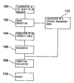
- FIG. 1 shows a flow chart representing a first embodiment of the method according to the present invention.
- FIG. 2 shows a flow chart representing a second embodiment of the method according to the present invention.
- a method which permits a correction of physically-conditioned errors in the measurement of an object; in the description of the preferred embodiments following hereinbelow, the method for optical microscopy is described as an exemplary method; to a person skilled in the art it will, however, be obvious that the method according to the present invention can be used for all image-forming measurement methods.
- an image of the object to be measured is produced according to the present invention, the imaged object is measured, and the measurement result is corrected with due regard to the object surroundings so that the corrected measurement result then corresponds to the actual physical dimensions of the object to be measured and can be used reliably in the case of further processing.
- FIG. 1 shows a first flow chart representing a first embodiment of the method according to the present invention.
- a first step 100 the object to be measured is illuminated by means of light, and in step 102 an image of the object to be measured is produced.
- an intensity image is produced in step 104 from the image produed in step 102 , and the imaged object is measured in step 106 .
- correction calculation in dependence on a measurement error determined takes place in step 108 and the corrected measurement result is outputted in step 110 .
- the possible measurement error is determined in step 112 in that the measurement error or the possible measurement error caused by the structural surroundings of the object is calculated in dependence on the image produced in step 102 and is then supplied for correction calculation in step 108 .
- the transfer/transmission characteristics of the measurement microscope are calculated on the basis of the characteristic data of the microscope, viz. the wavelength and the spectrum of the illumination source, the type of illumination (incident light or transmitted light), the magnification factor, the objective values (numerical aperture and sigma).
- the result of the measurement carried out in step 106 is corrected in step 108 in such a way that the effects of the optical “proximity effect” on the measurement result are eliminated so that the measurement value determined corresponds to the actual physical dimensions.
- this invention is used especially for objects to be measured having dimensions in the case of which the imaging processes used and the structural density cause the above-mentioned measurement errors, e.g. line broadening and the like.
- These objects have dimensions in the microscopic range, which are of the same order of magnitude as the wavelength of the illumination source, e.g. 0.5 ⁇ m to 10 ⁇ m.
- FIG. 2 a second embodiment of the method according to the present invention is described, the blocks and steps, respectively, which have already been described on the basis of FIG. 1 being designated by the same reference numerals.
- the present embodiment differs from the embodiment described in FIG. 1 insofar as the calculation of possible measurement errors is carried out independently of the image produced in step 102 .
- the data required for determining the measurement error are received in step 200 from an external source independently of the actually produced image.
- These external data include e.g. the original structure, for example in the form of a layout description, which represents the expected value of the object to be measured including its structural surroundings.
- the possible measurement error is calculated and the correction which has already been described making reference to FIG. 1 is carried out.
- the image can, according to one implementation, be produced in step 102 in such a way that only the object to be imaged is detected, without detecting the structure surrounding this object.
- the correction of the measurement errors caused by the surroundings is effected in the manner described hereinbefore on the basis of a calculation of a possible measurement error in step 200 .
- correction can take place in step 108 in dependence on a specific correction function which approximates to the ideal conditions.
Landscapes
- Physics & Mathematics (AREA)
- General Physics & Mathematics (AREA)
- Chemical & Material Sciences (AREA)
- Analytical Chemistry (AREA)
- Optics & Photonics (AREA)
- Length-Measuring Devices Using Wave Or Particle Radiation (AREA)
- Analysing Materials By The Use Of Radiation (AREA)
- Length Measuring Devices By Optical Means (AREA)
- Investigating Or Analysing Materials By Optical Means (AREA)
- Arrangements For Transmission Of Measured Signals (AREA)
- Sampling And Sample Adjustment (AREA)
- Testing Or Measuring Of Semiconductors Or The Like (AREA)
Abstract
Description
Claims (13)
Applications Claiming Priority (2)
| Application Number | Priority Date | Filing Date | Title |
|---|---|---|---|
| DE10027221 | 2000-05-31 | ||
| DE10027221A DE10027221A1 (en) | 2000-05-31 | 2000-05-31 | Procedure for correcting physical errors in the measurement of microscopic objects |
Publications (1)
| Publication Number | Publication Date |
|---|---|
| US6795574B1 true US6795574B1 (en) | 2004-09-21 |
Family
ID=7644366
Family Applications (1)
| Application Number | Title | Priority Date | Filing Date |
|---|---|---|---|
| US09/613,388 Expired - Fee Related US6795574B1 (en) | 2000-05-31 | 2000-07-11 | Method of correcting physically-conditioned errors in measurement of microscopic objects |
Country Status (8)
| Country | Link |
|---|---|
| US (1) | US6795574B1 (en) |
| EP (1) | EP1330628B1 (en) |
| JP (1) | JP2001343217A (en) |
| KR (1) | KR100470217B1 (en) |
| AT (1) | ATE267383T1 (en) |
| DE (2) | DE10027221A1 (en) |
| IL (2) | IL150726A0 (en) |
| WO (1) | WO2001092818A1 (en) |
Cited By (2)
| Publication number | Priority date | Publication date | Assignee | Title |
|---|---|---|---|---|
| US20060274934A1 (en) * | 2005-06-03 | 2006-12-07 | Vistec Semiconductor Systems Gmbh | Apparatus and method for improving measuring accuracy in the determination of structural data |
| US20090015833A1 (en) * | 2007-07-11 | 2009-01-15 | Vistec Semiconductor Systems Gmbh | Device and method for improving the measurement accuracy in an optical cd measurement system |
Families Citing this family (1)
| Publication number | Priority date | Publication date | Assignee | Title |
|---|---|---|---|---|
| DE10235437B4 (en) * | 2002-08-02 | 2007-09-20 | Pdf Solutions Gmbh | Method for correcting physical errors when measuring an object |
Citations (6)
| Publication number | Priority date | Publication date | Assignee | Title |
|---|---|---|---|---|
| US5650840A (en) * | 1994-09-13 | 1997-07-22 | Nikon Corporation | Focus detecting method and apparatus |
| US5863682A (en) * | 1996-02-23 | 1999-01-26 | Kabushiki Kaisha Toshiba | Charged particle beam writing method for determining optimal exposure dose prior to pattern drawing |
| US6048647A (en) * | 1994-04-05 | 2000-04-11 | Mitsubishi Denki Kabushiki Kaisha | Phase shift mask of attenuation type and manufacturing method thereof |
| US6167355A (en) * | 1997-02-28 | 2000-12-26 | Peter J. Fiekowsky | High accuracy particle dimension measurement system |
| US6178360B1 (en) * | 1998-02-05 | 2001-01-23 | Micron Technology, Inc. | Methods and apparatus for determining optimum exposure threshold for a given photolithographic model |
| US6337162B1 (en) * | 1998-03-26 | 2002-01-08 | Nikon Corporation | Method of exposure, photomask, method of production of photomask, microdevice, and method of production of microdevice |
Family Cites Families (3)
| Publication number | Priority date | Publication date | Assignee | Title |
|---|---|---|---|---|
| EP0845112B1 (en) * | 1995-08-07 | 2002-10-23 | Tomey Co., Ltd. | Reflecting microscope device |
| JP2001511247A (en) * | 1996-12-23 | 2001-08-07 | ルプレヒト−カールス−ウニヴェルジテート ハイデルベルク | Method and apparatus for measuring distance between object structures |
| IL127359A0 (en) * | 1998-12-01 | 1999-10-28 | Yeda Res & Dev | Computerized adaptive imaging |
-
2000
- 2000-05-31 DE DE10027221A patent/DE10027221A1/en not_active Withdrawn
- 2000-07-11 US US09/613,388 patent/US6795574B1/en not_active Expired - Fee Related
- 2000-07-25 JP JP2000223749A patent/JP2001343217A/en active Pending
-
2001
- 2001-05-31 AT AT01984527T patent/ATE267383T1/en not_active IP Right Cessation
- 2001-05-31 KR KR10-2002-7010194A patent/KR100470217B1/en not_active Expired - Fee Related
- 2001-05-31 WO PCT/EP2001/006200 patent/WO2001092818A1/en not_active Ceased
- 2001-05-31 DE DE50102355T patent/DE50102355D1/en not_active Expired - Fee Related
- 2001-05-31 EP EP01984527A patent/EP1330628B1/en not_active Expired - Lifetime
- 2001-05-31 IL IL15072601A patent/IL150726A0/en active IP Right Grant
-
2002
- 2002-07-14 IL IL150726A patent/IL150726A/en not_active IP Right Cessation
Patent Citations (6)
| Publication number | Priority date | Publication date | Assignee | Title |
|---|---|---|---|---|
| US6048647A (en) * | 1994-04-05 | 2000-04-11 | Mitsubishi Denki Kabushiki Kaisha | Phase shift mask of attenuation type and manufacturing method thereof |
| US5650840A (en) * | 1994-09-13 | 1997-07-22 | Nikon Corporation | Focus detecting method and apparatus |
| US5863682A (en) * | 1996-02-23 | 1999-01-26 | Kabushiki Kaisha Toshiba | Charged particle beam writing method for determining optimal exposure dose prior to pattern drawing |
| US6167355A (en) * | 1997-02-28 | 2000-12-26 | Peter J. Fiekowsky | High accuracy particle dimension measurement system |
| US6178360B1 (en) * | 1998-02-05 | 2001-01-23 | Micron Technology, Inc. | Methods and apparatus for determining optimum exposure threshold for a given photolithographic model |
| US6337162B1 (en) * | 1998-03-26 | 2002-01-08 | Nikon Corporation | Method of exposure, photomask, method of production of photomask, microdevice, and method of production of microdevice |
Cited By (2)
| Publication number | Priority date | Publication date | Assignee | Title |
|---|---|---|---|---|
| US20060274934A1 (en) * | 2005-06-03 | 2006-12-07 | Vistec Semiconductor Systems Gmbh | Apparatus and method for improving measuring accuracy in the determination of structural data |
| US20090015833A1 (en) * | 2007-07-11 | 2009-01-15 | Vistec Semiconductor Systems Gmbh | Device and method for improving the measurement accuracy in an optical cd measurement system |
Also Published As
| Publication number | Publication date |
|---|---|
| ATE267383T1 (en) | 2004-06-15 |
| EP1330628B1 (en) | 2004-05-19 |
| DE50102355D1 (en) | 2004-06-24 |
| EP1330628A1 (en) | 2003-07-30 |
| DE10027221A1 (en) | 2002-04-18 |
| KR20030003228A (en) | 2003-01-09 |
| JP2001343217A (en) | 2001-12-14 |
| IL150726A (en) | 2006-10-31 |
| IL150726A0 (en) | 2003-02-12 |
| KR100470217B1 (en) | 2005-02-05 |
| WO2001092818A1 (en) | 2001-12-06 |
| WO2001092818A8 (en) | 2002-02-21 |
Similar Documents
| Publication | Publication Date | Title |
|---|---|---|
| CN104272184B (en) | Method and inspection system for inspecting masks to identify lithographically significant defects | |
| JP6391170B2 (en) | Inspection device | |
| JPH11153550A (en) | Defect inspection method and defect inspection device | |
| KR20140020716A (en) | Defect inspection apparatus | |
| US8421026B2 (en) | Method and apparatus for mapping of line-width size distributions on photomasks | |
| JP6431786B2 (en) | Line width error acquisition method, line width error acquisition apparatus, and inspection system | |
| US8811713B2 (en) | Photomask inspection method, semiconductor device inspection method, and pattern inspection apparatus | |
| KR20230057462A (en) | Setup of sample inspection | |
| US5781657A (en) | Apparatus for inspecting pattern of photomask and method therefor | |
| US12361536B2 (en) | EUV mask inspection device, EUV mask inspection method, non-transitory computer-readable medium storing EUV mask inspection program, and EUV mask inspection system including a gray image based on design data of a pattern | |
| KR102013287B1 (en) | Instrumentation device and instrumentation method | |
| US6795574B1 (en) | Method of correcting physically-conditioned errors in measurement of microscopic objects | |
| US20140314305A1 (en) | Template inspection device | |
| US8879055B1 (en) | Inspection method and inspection apparatus | |
| US12062164B2 (en) | Pattern analysis system and method of manufacturing semiconductor device using the same | |
| US20060290930A1 (en) | Method and apparatus for inspecting pattern defects | |
| JP2000106336A (en) | Pattern inspection apparatus, pattern inspection method, and recording medium storing pattern inspection program | |
| JP2004144610A (en) | Wafer defect inspection apparatus | |
| US8154595B2 (en) | Device and method for automatic detection of incorrect measurements by means of quality factors | |
| US6888958B1 (en) | Method and apparatus for inspecting patterns | |
| JP2001266126A (en) | Defect detection method and apparatus, and mask manufacturing method | |
| JP2003227710A (en) | Defect imaging device and imaging method | |
| JP4234703B2 (en) | Defect inspection equipment | |
| US11443419B2 (en) | Reference image generation method and pattern inspection method | |
| US20170352141A1 (en) | Inspection method |
Legal Events
| Date | Code | Title | Description |
|---|---|---|---|
| AS | Assignment |
Owner name: APPLIED INTEGRATED SYSTEMS & SOFTWARE, GERMANY Free format text: ASSIGNMENT OF ASSIGNORS INTEREST;ASSIGNORS:HARTMANN, HANS;WAAS, THOMAS;EISENMANN, HANS;AND OTHERS;REEL/FRAME:011279/0692 Effective date: 20000918 Owner name: MUE TEC, GERMANY Free format text: ASSIGNMENT OF ASSIGNORS INTEREST;ASSIGNORS:HARTMANN, HANS;WAAS, THOMAS;EISENMANN, HANS;AND OTHERS;REEL/FRAME:011279/0692 Effective date: 20000918 |
|
| AS | Assignment |
Owner name: PDF SOLUTIONS GMBH, GERMANY Free format text: CHANGE OF NAME;ASSIGNOR:APPLIED INTERGRATED SYSTEMS & SOFTWARE;REEL/FRAME:011791/0237 Effective date: 20001005 |
|
| CC | Certificate of correction | ||
| FPAY | Fee payment |
Year of fee payment: 4 |
|
| FEPP | Fee payment procedure |
Free format text: PAYOR NUMBER ASSIGNED (ORIGINAL EVENT CODE: ASPN); ENTITY STATUS OF PATENT OWNER: SMALL ENTITY |
|
| REMI | Maintenance fee reminder mailed | ||
| LAPS | Lapse for failure to pay maintenance fees | ||
| STCH | Information on status: patent discontinuation |
Free format text: PATENT EXPIRED DUE TO NONPAYMENT OF MAINTENANCE FEES UNDER 37 CFR 1.362 |
|
| FP | Lapsed due to failure to pay maintenance fee |
Effective date: 20120921 |