US6791802B2 - Magnetic head device having suspension with microactuator bonded thereto - Google Patents
Magnetic head device having suspension with microactuator bonded thereto Download PDFInfo
- Publication number
- US6791802B2 US6791802B2 US10/081,245 US8124502A US6791802B2 US 6791802 B2 US6791802 B2 US 6791802B2 US 8124502 A US8124502 A US 8124502A US 6791802 B2 US6791802 B2 US 6791802B2
- Authority
- US
- United States
- Prior art keywords
- adhesive resin
- slider
- supporting member
- elastic supporting
- magnetic head
- Prior art date
- Legal status (The legal status is an assumption and is not a legal conclusion. Google has not performed a legal analysis and makes no representation as to the accuracy of the status listed.)
- Expired - Lifetime, expires
Links
Images


Classifications
-
- G—PHYSICS
- G11—INFORMATION STORAGE
- G11B—INFORMATION STORAGE BASED ON RELATIVE MOVEMENT BETWEEN RECORD CARRIER AND TRANSDUCER
- G11B5/00—Recording by magnetisation or demagnetisation of a record carrier; Reproducing by magnetic means; Record carriers therefor
- G11B5/48—Disposition or mounting of heads or head supports relative to record carriers ; arrangements of heads, e.g. for scanning the record carrier to increase the relative speed
- G11B5/54—Disposition or mounting of heads or head supports relative to record carriers ; arrangements of heads, e.g. for scanning the record carrier to increase the relative speed with provision for moving the head into or out of its operative position or across tracks
- G11B5/55—Track change, selection or acquisition by displacement of the head
- G11B5/5521—Track change, selection or acquisition by displacement of the head across disk tracks
- G11B5/5552—Track change, selection or acquisition by displacement of the head across disk tracks using fine positioning means for track acquisition separate from the coarse (e.g. track changing) positioning means
-
- H10W72/5522—
-
- Y—GENERAL TAGGING OF NEW TECHNOLOGICAL DEVELOPMENTS; GENERAL TAGGING OF CROSS-SECTIONAL TECHNOLOGIES SPANNING OVER SEVERAL SECTIONS OF THE IPC; TECHNICAL SUBJECTS COVERED BY FORMER USPC CROSS-REFERENCE ART COLLECTIONS [XRACs] AND DIGESTS
- Y10—TECHNICAL SUBJECTS COVERED BY FORMER USPC
- Y10T—TECHNICAL SUBJECTS COVERED BY FORMER US CLASSIFICATION
- Y10T29/00—Metal working
- Y10T29/49—Method of mechanical manufacture
- Y10T29/49002—Electrical device making
- Y10T29/4902—Electromagnet, transformer or inductor
- Y10T29/49021—Magnetic recording reproducing transducer [e.g., tape head, core, etc.]
- Y10T29/49027—Mounting preformed head/core onto other structure
- Y10T29/4903—Mounting preformed head/core onto other structure with bonding
Definitions
- the present invention relates to a magnetic head device comprising a piezoelectric element.
- FIG. 6 is a plan view showing an example of a conventional hard disk device.
- the hard disk device shown in FIG. 6 comprises a magnetic disk 101 , a spindle motor 102 for driving the magnetic disk 101 to rotate, a carriage 103 , a load beam 104 , a slider 105 , and a voice coil motor 106 .
- a magnetic head device schematically comprises the load beam 104 and the slider 105 .
- the base end 104 b of the load beam 104 serving as a supporting member is connected to the tip 103 a of the carriage 103 comprising a rigid material, and the slider 105 is mounted at the tip 104 a of the load beam 104 through a flexure (not shown in the drawing).
- the carriage 103 and the load beam 104 are driven in the radial direction of the magnetic disk 101 by the voice coil motor 106 to perform the seek operation of moving a reproducing element and recording element mounted on the slider 105 onto a desired recording track, and the tracking operation of finely controlling the positions of the reproducing element and the recording element to keep them on a center line of the recording track.
- a microactuator is mounted on the load beam 104 so that only the tip of the load beam 104 can be moved by the microactuator to perform the tracking operation.
- FIG. 7 is a perspective view of the load beam 104
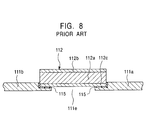
- FIG. 8 is a sectional view showing the principal portion of the load beam 104 shown in FIG. 7 .
- the load beam 104 is made of a stainless steel leaf spring material, and comprises a fixed base end 111 a held by the carriage, and an oscillating portion 111 b oscillatable horizontally relative to the fixed base end 111 a .
- the load beam 104 further comprises arms 111 c formed on both sides of the front end of the fixed base end 111 a to extend in the longitudinal direction of the fixed base end 111 a .
- the oscillating portion 111 b is connected to the arms 111 c through elastic supporting portions 111 d.
- piezoelectric elements 112 and 113 serving as microactuators are placed over a void 111 e between the oscillating portion 111 b and the fixed base end 111 a.
- the piezoelectric elements 112 and 113 comprise piezoelectric layers 112 a and 113 a made of a piezoelectric material such as lead titanate zirconate (PTZ), and electrode layers 112 b and 112 c , and electrode layers 113 b and 113 c , respectively, made of gold films formed above and below the piezoelectric layers 112 a and 113 a.
- PTZ lead titanate zirconate
- the electrode layers 112 c and 113 c of the piezoelectric elements 112 and 113 are bonded to the oscillating portion 111 b and the fixed base end 111 a with an adhesive resin 115
- reference numeral 121 denotes a slider mounted at the tip of the oscillating portion 111 b through a flexure (not shown in the drawing).
- the piezoelectric elements 112 and 113 are elements which produce strain when a voltage is applied through the electrode layers 112 b and 112 c , and the electrode layers 113 b and 113 c , respectively.
- the piezoelectric layers 112 a and 113 a of the piezoelectric elements 112 and 113 are polarized in the thickness direction, but the polarization directions of the piezoelectric elements 112 and 113 are opposite to each other. Therefore, when the same potential is applied to the electrode layers 112 c and 113 c , one of the piezoelectric elements extends in the longitudinal direction, while the other piezoelectric element shrinks in the longitudinal direction.
- the elastic supporting portions 111 d are deformed to change the position of the slider 121 mounted at the tip of the oscillating portion 111 b .
- the slider 121 mounted at the tip of the oscillating portion 111 b can be finely moved in the track width direction to perform the fine tracking operation.
- the precision of the tracking operation must be increased as the recording density of the magnetic disk 101 increases.
- the load beam 104 enables the precise tracking operation, and is thus adaptable for improving the recording density.
- thermosetting epoxy resin As the adhesive resin 115 for bonding the piezoelectric elements 112 and 113 and the oscillating portion 111 b and the fixed base end 111 a , a thermosetting epoxy resin is conventionally used.
- the epoxy resin is roughly classified into a one-component type and a two-component type.
- thermosetting epoxy resin cannot be temporarily hardened by light irradiation, and thus a bonded portion must be fixed by a jig or the like until curing is completed, thereby causing the problem of deteriorating manufacturing efficiency.
- a powdery curing agent is added to an epoxy solution as a main agent, and then dispersed in the epoxy solution by heating to start curing.
- the viscosity of the epoxy solution decreases until the temperature is increased to the curing temperature, thereby making the mixed state of the curing agent and the epoxy solution heterogeneous to leave an uncured portion in some cases.
- the uncured portion causes the occurrence of out gases, spots due to dissolution and re-adhesion of the uncured portion, etc., causing the problem of deteriorating the reliability of a magnetic head device.
- the uncured portion does not occur.
- the viscosity greatly varies with time during mixing of the main agent and the curing agent, thereby causing the problem of complicating handling of the resin after mixing.
- the acrylic adhesive resin is cured by radical polymerization, but peroxide radicals occur due to contact with atmospheric oxygen to cause reaction deactivation inhibition. This causes the problem of increasing the amount of the out gases produced, and deteriorating humidity resistance and heat resistance to deteriorate the reliability of the magnetic head device.
- the present invention has the following construction:
- a magnetic head device of the present invention comprises a slider comprising a reproducing element for detecting magnetic signals recorded on a recording medium, and a recording element for recording magnetic signals on the recording medium; an elastic supporting member for supporting the slider; and a piezoelectric element mounted on the elastic supporting member, for deforming the elastic supporting member to change the position of the slider, wherein the piezoelectric element and the elastic supporting member are bonded together with a photo-curing and thermosetting epoxy adhesive resin having a Young's modulus of 1 GPa or more at 25° C., and a glass transition temperature of 90° C. or more.
- the piezoelectric element and the elastic supporting member are bonded together with the photocuring and thermosetting epoxy adhesive resin, and thus the adhesive resin can be temporarily cured by light irradiation to temporarily fix the piezoelectric element without using a jig or the like, thereby increasing manufacturing efficiency.
- an epoxy resin as a main component of the adhesive resin is cured by cationic polymerization, and thus does not produce reaction deactivation inhibition due to oxygen, thereby increasing the reliability of the magnetic head device.
- the Young's modulus at 25° C. is 1 GPa or more, and the glass transition temperature is 90° C. or more, rigidity of the adhesive resin can be kept high in the practical temperature region of 90° C. or less. Therefore, the piezoelectric element and the elastic supporting member are bonded together through a rigid material, permitting secured propagation of a displacement of the piezoelectric element to the elastic supporting member, and the precise tracking operation.
- the elastic supporting member comprises a fixed base end and an oscillating portion which is connected to the fixed base end to support the slider and which can be oscillated by the piezoelectric element relative to the fixed base end.
- the piezoelectric element is bonded by the photocuring and thermosetting epoxy adhesive resin so as to be placed over the space between the fixed base end and the oscillating portion.
- the piezoelectric element is bonded to the fixed base end and the oscillating portion by the photocuring and thermosetting epoxy adhesive resin, and thus the piezoelectric element is bonded to the fixed base end and the oscillating portion through a rigid material, thereby permitting a precise displacement of the oscillating portion due to the piezoelectric element.
- FIG. 1 is a plan view showing an example of a hard disk device comprising a magnetic head device according to an embodiment of the present invention
- FIG. 2 is a perspective view of the magnetic head device of the embodiment shown in FIG. 1;
- FIG. 3 is an enlarged sectional view taken long line III—III in FIG. 2;
- FIG. 4 is a graph showing the relation between the displacement of a slider and the Young's modulus of an adhesive resin
- FIG. 5 is a graph showing the temperature dependency of the Young's modulus of an adhesive resin
- FIG. 6 is a plan view showing an example of a conventional hard disk device
- FIG. 7 is a perspective view of a conventional magnetic head device.
- FIG. 8 is an enlarged sectional view showing a principal portion of the conventional magnetic head device shown in FIG. 7 .
- FIG. 1 is a plan view showing an example of a hard disk device comprising a magnetic head device according to an embodiment of the present invention
- FIG. 2 is a perspective view of the magnetic head of the embodiment shown in FIG. 2
- FIG. 3 is an enlarged sectional view taken along line III-III′ in FIG. 2 .
- the hard disk device shown in FIG. 1 comprises a magnetic disk 1 , a spindle motor 2 for driving the magnetic disk 1 to rotate, a carriage 3 , a load beam 11 serving as an elastic supporting member, a slider 21 , and a voice coil motor 6 .
- the load beam 11 is connected to the tip 3 a of the carriage 3 serving as a rigid supporting member to be supported thereby.
- the voice coil motor 6 is mounted on the base end 3 b of the carriage 3 .
- the magnetic head device 10 of the present invention schematically comprises the load beam 11 and the slider 21 .
- the slider 21 is made of a ceramic material, and mounted on the tip of the load beam 11 . Also, as shown in FIG. 2, a thin film element 21 a is provided at the trailing-side end T of the slider 21 , and an ABS (flying surface) is formed on the recording medium-facing side of the slider 21 .
- the thin film element 21 a shown in FIG. 2 is a combination type thin film element comprising both a reproducing element (MR head) for reproducing magnetic recording signals recorded on a recording medium and a recording element (inductive head) for recording magnetic signals on the recording medium.
- the reproducing element comprises, for example, a magnetoresistive element such as a spin valve film utilizing a magnetoresistive effect, and a shield layer made of a magnetic material.
- the recording element comprises a patterned core and coil both of which are made of a magnetic material.
- piezoelectric elements 12 and 13 are mounted on the load beam 11 serving as the elastic supporting member for supporting the slider 21 .
- the load beam 11 is made of a stainless steel leaf spring material, and comprises the fixed base end 11 a supported by the carriage 3 , and the oscillating portion 11 b oscillatable horizontally relative to the fixed base end 11 a .
- the load beam 11 further comprises arms 11 c formed on both sides of the front end of the fixed base end 11 a so as to extend in the longitudinal direction of the fixed base end 11 a .
- the oscillating portion 11 b is connected to the arms 11 c through elastic supporting portions 11 d.
- the piezoelectric elements 12 and 13 are placed over the void 11 e between the oscillating portion 11 b and the fixed base end 11 a.
- the piezoelectric elements 12 and 13 comprise piezoelectric layers 12 a and 13 a each mainly composed of a piezoelectric material such as lead titanate zirconate (lead zirconate titanate) or the like, and a pair of electrode layers 12 b and 12 c , and a pair of electrode layers 13 b and 12 c , which hold the piezoelectric layers 12 a and 13 a , respectively, therebetween.
- a piezoelectric material such as lead titanate zirconate (lead zirconate titanate) or the like
- the bonded structure of the piezoelectric elements 12 and 13 and the load beam is described in further detail below with reference to FIG. 3 .
- the oscillating portion 11 b has a notch 11 f provided on the void side thereof, and the fixed base end 11 a also has a notch 11 g provided on the void side thereof.
- the piezoelectric element 12 is arranged across the space between the notches 11 f and 11 g with the electrode layer 12 c facing the notch side, i.e., facing the fixed base end 11 a and the oscillating portion 11 b .
- the photocuring and thermosetting epoxy adhesive resin 15 (referred to as the “adhesive resin 15” hereinafter) is coated on the notches 11 f and 11 g so that the piezoelectric element 12 is bonded to the notches 11 f and 11 g through the adhesive resin 15 .
- FIG. 3 shows only the piezoelectric element 12 , the bonded structure of the other piezoelectric element 13 is substantially the same as the structure shown in FIG. 3 .
- the load beam 11 shown in FIG. 2 is connected to an earth.
- the electrode layers 12 b and 13 b of the piezoelectric elements 12 and 13 are electrically connected to the load beam 11 through gold wires 14 a to be connected to the earth.
- the material for electrically connecting the electrode layers 12 b and 13 b to the load beam 11 is not limited to the gold wires 14 a , and conductive paste or the like may be used.
- the electrode layers 12 c and 13 c are connected to a gold wire 14 b passing through the void 11 e , the gold wire 14 b being connected to a control circuit not shown in the drawing through a terminal 14 c.
- the piezoelectric elements 12 and 13 are elements which produce strain when a voltage is applied to the electrode layers 12 b and 12 c , and the electrode layers 13 b and 13 c , respectively.
- the piezoelectric layers 12 a and 13 a of the piezoelectric elements 12 and 13 are polarized in the thickness direction.
- the polarization directions of the piezoelectric elements 12 and 13 are opposite to each other, and when the same voltage is applied to the electrode layers 12 c and 13 c through the gold wires 14 b , one of the piezoelectric elements extends in the longitudinal direction, while the other piezoelectric element shrinks in the longitudinal direction.
- the elastic supporting portions 11 d are distorted to change the position of the slider 21 mounted at the tip of the oscillating portion 11 b .
- the slider 21 mounted at the tip of the oscillating portion 11 b can be moved in the track width direction (the direction of a double arrow shown in FIG. 2 ), permitting the tracking operation.
- the adhesive resin 15 used for bonding the piezoelectric elements 12 and 13 to the fixed base end 11 a and the oscillating portion 11 b is an epoxy adhesive resin referred to as a “photocuring and thermosetting type”, and cured by either of ultraviolet irradiation and heating.
- the adhesive resin 15 has the property that the Young's modulus in a cured state at 25° C. is 1 GPa or more, and the glass transition temperature is 90° C. or more.
- the oscillating portion 11 b is oscillated due to displacements of the piezoelectric elements 12 and 13 , and thus the piezoelectric elements 12 and 13 must be bonded to the fixed base end 11 a and the oscillating portion 11 b through a rigid material. Therefore, the adhesive resin 15 used in the present invention must be rigid in the practical temperature region of the magnetic head device.
- the flexibility of an adhesive resin is mainly determined by the Young's modulus and the glass transition temperature. Therefore, in the present invention, by setting the Young's modulus and the glass transition temperature of the adhesive resin 15 to 1 GPa or more and 90° C. or more, respectively, sufficient rigid bonding can be realized.
- the Young's modulus of the adhesive resin 15 at 25° C. is 1 GPa or more
- the rigidity of the adhesive resin 15 itself is improved to decrease the displacement of the adhesive resin 15 with an external stress applied, thereby permitting secured transmission of the displacements of the piezoelectric elements 12 and 13 to the fixed base end 11 a and the oscillating portion 11 b . Therefore, the oscillating portion 11 b can be precisely displaced without absorption of the displacements of the piezoelectric elements 12 and 13 by the adhesive resin 1 , improving the precision of the tracking operation.
- the glass transition temperature of the adhesive resin 15 is preferably in the range of 90° C. to 200° C. With the glass transition temperature of 90° C. or more, the Young's modulus is not extremely decreased at 5 to 60° C. in the practical temperature region of the magnetic head device to maintain the rigidity of the adhesive resin 15 itself. Thus, the oscillating portion 11 b can be precisely displaced without absorption of the displacements of the piezoelectric elements 12 and 13 by the adhesive resin 15 , thereby improving the precision of the tracking operation.
- the reason for setting the glass transition temperature to 200° C. or less is that the epoxy adhesive resin 15 has a heat resistance temperature of 200° C. or less, and is thermally decomposed at a temperature exceeding 200° C., and it is thus impractical to set the upper limit of the glass transition temperature to 200° C. or more.
- the glass transition temperature of the adhesive resin 15 can be controlled by controlling the thermosetting conditions of the adhesive resin 15 .
- the glass transition temperature is 90° C. in the case of curing by heating at 110° C.; the glass transition temperature is about 100° C. in the case of curing by heating at 130° C.
- the glass transition temperature is about 20 to 30° C. lower than the curing temperature.
- the adhesive resin 15 used in the present invention is referred to as the “photocuring and thermosetting type”, and can be cured by either of ultraviolet irradiation and heating. By utilizing this property, the manufacturing efficiency of the magnetic head device can be improved.
- the adhesive resin 15 is coated in an uncured state on the notches 11 f and 11 g , and the piezoelectric elements 12 and 13 are arranged over the space between the fixed base end 11 a and the oscillating portion 11 b . Then, the adhesive resin 15 is partially cured by ultraviolet irradiation to temporarily fix the piezoelectric elements 12 and 13 to the fixed base end 11 a and the oscillating portion 11 b . In this state, the bonded positions of the piezoelectric elements 12 and 13 are checked to examine whether or not a problem with design occurs. If it is confirmed that there is no problem with design, the adhesive resin 15 is thermally set by heating.
- the piezoelectric elements 12 and 13 are temporarily fixed by ultraviolet irradiation, and then the adhesive resin 15 is completely thermally set, thereby eliminating the need for a jig for temporarily fixing the piezoelectric elements 12 and 13 . This can improve the manufacturing efficiency of the magnetic head device.
- the slider was mounted at the tip of the load beam shown in FIG. 2, and a photocuring and thermosetting epoxy adhesive resin was coated on each of notches of the oscillating portion and the fixed base end of the load beam. Then, a piezoelectric element was mounted and bonded to the load beam by curing the adhesive resin by ultraviolet irradiation and heating to manufacture a magnetic head device.
- the thus-manufactured magnetic head device was incorporated into the hard disk device shown in FIG. 1, and a voltage of ⁇ 30 V (frequency 1 kHz) was applied to the piezoelectric element to perform the tracking operation by the slider. At this time, the displacement of the slider was measured. The results are shown in FIG. 4 .
- FIG. 4 shows the relationship between the displacement of the slider in the track width direction and the Young's modulus of the adhesive resin. The Young's modulus was measured at 25° C.
- FIG. 4 indicates that with the Young's modulus in the range of 1 GPa or more, the displacement of the slider becomes substantially constant at a value exceeding 4 ⁇ 10 ⁇ 2 ( ⁇ m/V). On the other hand, with the Young's modulus in the range of less than 1 GPa, the displacement of the slider decreases as the Young's modulus decreases.
- the piezoelectric element Since the displacement of the slider is relatively high and constant when the Young's modulus is 1 GPa or more, the piezoelectric element is possibly bonded to the load beam through a rigid material, and the displacement of the piezoelectric element is possibly reflected in the displacement of the slider without being absorbed by the adhesive resin.
- the displacement of the slider changes with changes in the Young's modulus. It is thus found that the piezoelectric element is bonded to the load beam through an elastic material, and the displacement of the piezoelectric element is absorbed by the adhesive resin, thereby making it impossible for the slider to be displaced following the displacement of the piezoelectric element.
- the slider can precisely perform the tracking operation.
- FIG. 5 shows the temperature dependency of the Young's modulus of each of adhesive resins having glass transition temperatures of 75 to 100° C.
- the adhesive resin having a glass transition temperature Tg of 90° C. was cured by heating at 110° C.; the adhesive resin having a glass transition temperature Tg of 100° C. was cured by heating at 130° C.; the adhesive resin having a glass transition temperature Tg of 75° C. was cured by heating at 85° C.
- FIG. 5 indicates that the adhesive resins each having a glass transition temperature of 90° C. or more exhibit a Young's modulus of 1 ⁇ 10 9 Pa (1 GPa) or more in the practical temperature region of 0 to 75° C.
- the adhesive resin having a glass transition temperature of 75° C. exhibits a Young's modulus of 1 ⁇ 10 9 Pa (1 GPa) or less at 50° C. or more.
- the piezoelectric element can be bonded to the load beam through a rigid material in the practical temperature region of 75° C. or less, thereby permitting the precise tracking operation.
- a piezoelectric element is bonded to an elastic supporting member with a photocuring and thermosetting epoxy adhesive resin, and thus the adhesive resin can be temporarily curded by light irradiation to temporarily fix the piezoelectric element without using a jig or the like. This can improve the manufacturing efficiency.
- an epoxy resin as a main component of the adhesive resin is cured by cationic polymerization, and thus does not produce reaction deactivation inhibition due to oxygen. Therefore, the reliability of the magnetic head device can be improved.
- the adhesive resin has a Young's modulus of 1 GPa or more at 25° C., and a glass transition temperature of 90° C. or more, and thus rigidity of the adhesive resin can be maintained at a high level in the practical temperature region of 90° C. or less. This can achieve bonding of the piezoelectric element and the elastic supporting member through a rigid material, and thus permits precise transmission of the displacement of the piezoelectric element to the elastic supporting member and the precise tracking operation.
Landscapes
- Supporting Of Heads In Record-Carrier Devices (AREA)
- Moving Of The Head To Find And Align With The Track (AREA)
- Adjustment Of The Magnetic Head Position Track Following On Tapes (AREA)
Abstract
Description
Claims (2)
Applications Claiming Priority (2)
| Application Number | Priority Date | Filing Date | Title |
|---|---|---|---|
| JP2001-049351 | 2001-02-23 | ||
| JP2001049351A JP3792521B2 (en) | 2001-02-23 | 2001-02-23 | Magnetic head device |
Publications (2)
| Publication Number | Publication Date |
|---|---|
| US20020118492A1 US20020118492A1 (en) | 2002-08-29 |
| US6791802B2 true US6791802B2 (en) | 2004-09-14 |
Family
ID=18910465
Family Applications (1)
| Application Number | Title | Priority Date | Filing Date |
|---|---|---|---|
| US10/081,245 Expired - Lifetime US6791802B2 (en) | 2001-02-23 | 2002-02-21 | Magnetic head device having suspension with microactuator bonded thereto |
Country Status (2)
| Country | Link |
|---|---|
| US (1) | US6791802B2 (en) |
| JP (1) | JP3792521B2 (en) |
Cited By (26)
| Publication number | Priority date | Publication date | Assignee | Title |
|---|---|---|---|---|
| US20050023936A1 (en) * | 2003-07-29 | 2005-02-03 | Murata Manufacturing Co., Ltd. | Piezoelectric device |
| US7218481B1 (en) * | 2002-10-07 | 2007-05-15 | Hutchinson Technology Incorporated | Apparatus for insulating and electrically connecting piezoelectric motor in dual stage actuator suspension |
| US7280319B1 (en) * | 2005-01-31 | 2007-10-09 | Western Digital Technologies, Inc. | Suspension assembly with piezoelectric microactuators electrically connected to a folded flex circuit segment |
| US20100073824A1 (en) * | 2008-09-19 | 2010-03-25 | Nhk Spring Co., Ltd. | Head suspension |
| US20100097723A1 (en) * | 2008-10-21 | 2010-04-22 | Tdk Corporation | Thin-film piezoelectric device, production method thereof, head gimbals assembly using the thin-film piezoelectric device, and hard disk drive using the head gimbals assembly |
| US20100195252A1 (en) * | 2009-02-04 | 2010-08-05 | Nhk Spring Co., Ltd. | Electrode structure of piezoelectric element, method of forming electrode of piezoelectric element, piezoelectric actuator, and head suspension |
| US20110085269A1 (en) * | 2009-10-09 | 2011-04-14 | Nhk Spring Co., Ltd. | Disk drive suspension and manufacturing method therefor |
| US20120087047A1 (en) * | 2010-10-07 | 2012-04-12 | Nhk Spring Co., Ltd. | Piezoelectric actuator and head suspension |
| US8675314B1 (en) | 2013-08-21 | 2014-03-18 | Hutchinson Technology Incorporated | Co-located gimbal-based dual stage actuation disk drive suspensions with offset motors |
| US8681456B1 (en) | 2012-09-14 | 2014-03-25 | Hutchinson Technology Incorporated | Co-located gimbal-based dual stage actuation disk drive suspensions |
| US8717712B1 (en) | 2013-07-15 | 2014-05-06 | Hutchinson Technology Incorporated | Disk drive suspension assembly having a partially flangeless load point dimple |
| US8792214B1 (en) | 2013-07-23 | 2014-07-29 | Hutchinson Technology Incorporated | Electrical contacts to motors in dual stage actuated suspensions |
| US8861141B2 (en) * | 2012-08-31 | 2014-10-14 | Hutchinson Technology Incorporated | Damped dual stage actuation disk drive suspensions |
| US8891206B2 (en) | 2012-12-17 | 2014-11-18 | Hutchinson Technology Incorporated | Co-located gimbal-based dual stage actuation disk drive suspensions with motor stiffener |
| US8896970B1 (en) | 2013-12-31 | 2014-11-25 | Hutchinson Technology Incorporated | Balanced co-located gimbal-based dual stage actuation disk drive suspensions |
| US8896969B1 (en) | 2013-05-23 | 2014-11-25 | Hutchinson Technology Incorporated | Two-motor co-located gimbal-based dual stage actuation disk drive suspensions with motor stiffeners |
| US8896968B2 (en) | 2012-10-10 | 2014-11-25 | Hutchinson Technology Incorporated | Co-located gimbal-based dual stage actuation disk drive suspensions with dampers |
| US8941951B2 (en) | 2012-11-28 | 2015-01-27 | Hutchinson Technology Incorporated | Head suspension flexure with integrated strain sensor and sputtered traces |
| US9001469B2 (en) | 2012-03-16 | 2015-04-07 | Hutchinson Technology Incorporated | Mid-loadbeam dual stage actuated (DSA) disk drive head suspension |
| US9070392B1 (en) | 2014-12-16 | 2015-06-30 | Hutchinson Technology Incorporated | Piezoelectric disk drive suspension motors having plated stiffeners |
| US9245555B2 (en) | 2010-05-24 | 2016-01-26 | Hutchinson Technology Incorporated | Low resistance ground joints for dual stage actuation disk drive suspensions |
| US9318136B1 (en) | 2014-12-22 | 2016-04-19 | Hutchinson Technology Incorporated | Multilayer disk drive motors having out-of-plane bending |
| US9431042B2 (en) | 2014-01-03 | 2016-08-30 | Hutchinson Technology Incorporated | Balanced multi-trace transmission in a hard disk drive flexure |
| US9646638B1 (en) | 2016-05-12 | 2017-05-09 | Hutchinson Technology Incorporated | Co-located gimbal-based DSA disk drive suspension with traces routed around slider pad |
| US9734852B2 (en) | 2015-06-30 | 2017-08-15 | Hutchinson Technology Incorporated | Disk drive head suspension structures having improved gold-dielectric joint reliability |
| US9824704B2 (en) | 2015-02-17 | 2017-11-21 | Hutchinson Technology Incorporated | Partial curing of a microactuator mounting adhesive in a disk drive suspension |
Families Citing this family (20)
| Publication number | Priority date | Publication date | Assignee | Title |
|---|---|---|---|---|
| JP4364075B2 (en) * | 2004-06-29 | 2009-11-11 | 富士通株式会社 | Moving mechanism using piezoelectric actuator and magnetic disk device having such moving mechanism |
| US7417830B1 (en) * | 2005-08-31 | 2008-08-26 | Magnecomp Corporation | Head gimbal assembly with dual-mode piezo microactuator |
| US7667932B2 (en) * | 2006-01-17 | 2010-02-23 | Samsung Electronics, Co., Ltd. | Method and apparatus using embedded sensor in a piezoelectric micro-actuator in a hard disk drive |
| US20080002304A1 (en) * | 2006-06-30 | 2008-01-03 | Sae Magnetics (H.K.) Ltd. | Micro-actuator mounting arrangement and manufacturing method thereof |
| JP2008235674A (en) * | 2007-03-22 | 2008-10-02 | Toyota Motor Corp | Power module and vehicle inverter |
| JP5053217B2 (en) * | 2008-09-24 | 2012-10-17 | 日本発條株式会社 | Head suspension |
| CN101714359B (en) * | 2008-10-03 | 2012-05-02 | 日本发条株式会社 | Head suspension and method of manufacturing head suspension |
| JP4907675B2 (en) * | 2009-01-15 | 2012-04-04 | 日本発條株式会社 | Wiring connection structure of piezoelectric element, piezoelectric actuator, and head suspension |
| JP5138635B2 (en) * | 2009-05-15 | 2013-02-06 | 日本発條株式会社 | Head suspension |
| JP5174743B2 (en) * | 2009-05-21 | 2013-04-03 | 日本発條株式会社 | Head suspension |
| US8542465B2 (en) * | 2010-03-17 | 2013-09-24 | Western Digital Technologies, Inc. | Suspension assembly having a microactuator electrically connected to a gold coating on a stainless steel surface |
| US8339748B2 (en) | 2010-06-29 | 2012-12-25 | Western Digital Technologies, Inc. | Suspension assembly having a microactuator bonded to a flexure |
| US8665567B2 (en) * | 2010-06-30 | 2014-03-04 | Western Digital Technologies, Inc. | Suspension assembly having a microactuator grounded to a flexure |
| JP5158990B2 (en) * | 2010-08-30 | 2013-03-06 | サンコール株式会社 | Magnetic head suspension and manufacturing method thereof |
| US9509235B2 (en) * | 2011-06-27 | 2016-11-29 | Canon Kabushiki Kaisha | Piezoelectric element, oscillatory wave motor, and optical apparatus |
| US9093117B2 (en) | 2012-03-22 | 2015-07-28 | Hutchinson Technology Incorporated | Ground feature for disk drive head suspension flexures |
| JP2013206476A (en) * | 2012-03-27 | 2013-10-07 | Tdk Corp | Magnetic head and magnetic recording and reproducing device |
| JP6808968B2 (en) * | 2016-04-28 | 2021-01-06 | Tdk株式会社 | Piezoelectric element, piezoelectric actuator and manufacturing method of piezoelectric element |
| DE102019200049A1 (en) | 2019-01-04 | 2020-07-09 | Aktiebolaget Skf | A SUSPENSION ASSEMBLY |
| DE102019200048A1 (en) * | 2019-01-04 | 2020-07-09 | Aktiebolaget Skf | Suspension spring |
Citations (5)
| Publication number | Priority date | Publication date | Assignee | Title |
|---|---|---|---|---|
| US5696652A (en) | 1995-07-06 | 1997-12-09 | Alps Electric Co., Ltd. | Magnetic head device using an adhesive having both photosetting and thermosetting properties, and method for producing same |
| US5764444A (en) | 1991-07-23 | 1998-06-09 | Fujitsu Limited | Mechanism for minute movement of a head |
| US5898544A (en) | 1997-06-13 | 1999-04-27 | Hutchinson Technology Incorporated | Base plate-mounted microactuator for a suspension |
| US6239953B1 (en) | 1999-10-15 | 2001-05-29 | Magnecomp Corp. | Microactuated disk drive suspension with heightened stroke sensitivity |
| US6552878B2 (en) * | 1998-08-05 | 2003-04-22 | Hitachi, Ltd. | Magnetic disk apparatus |
-
2001
- 2001-02-23 JP JP2001049351A patent/JP3792521B2/en not_active Expired - Fee Related
-
2002
- 2002-02-21 US US10/081,245 patent/US6791802B2/en not_active Expired - Lifetime
Patent Citations (6)
| Publication number | Priority date | Publication date | Assignee | Title |
|---|---|---|---|---|
| US5764444A (en) | 1991-07-23 | 1998-06-09 | Fujitsu Limited | Mechanism for minute movement of a head |
| US5696652A (en) | 1995-07-06 | 1997-12-09 | Alps Electric Co., Ltd. | Magnetic head device using an adhesive having both photosetting and thermosetting properties, and method for producing same |
| US5898544A (en) | 1997-06-13 | 1999-04-27 | Hutchinson Technology Incorporated | Base plate-mounted microactuator for a suspension |
| US6046888A (en) | 1997-06-13 | 2000-04-04 | Hutchinson Technology Incorporated | Base plate-mounted microactuator for a suspension |
| US6552878B2 (en) * | 1998-08-05 | 2003-04-22 | Hitachi, Ltd. | Magnetic disk apparatus |
| US6239953B1 (en) | 1999-10-15 | 2001-05-29 | Magnecomp Corp. | Microactuated disk drive suspension with heightened stroke sensitivity |
Cited By (56)
| Publication number | Priority date | Publication date | Assignee | Title |
|---|---|---|---|---|
| US7218481B1 (en) * | 2002-10-07 | 2007-05-15 | Hutchinson Technology Incorporated | Apparatus for insulating and electrically connecting piezoelectric motor in dual stage actuator suspension |
| US20050023936A1 (en) * | 2003-07-29 | 2005-02-03 | Murata Manufacturing Co., Ltd. | Piezoelectric device |
| US7440236B1 (en) | 2003-10-07 | 2008-10-21 | Hutchinson Technology Incorporated | Apparatus for insulating and electronically connecting piezoelectric motor in dual stage actuator suspension from the same side of the suspension |
| US7280319B1 (en) * | 2005-01-31 | 2007-10-09 | Western Digital Technologies, Inc. | Suspension assembly with piezoelectric microactuators electrically connected to a folded flex circuit segment |
| US8199441B2 (en) * | 2008-09-19 | 2012-06-12 | Nhk Spring Co., Ltd. | Head suspension |
| US20100073824A1 (en) * | 2008-09-19 | 2010-03-25 | Nhk Spring Co., Ltd. | Head suspension |
| US20100097723A1 (en) * | 2008-10-21 | 2010-04-22 | Tdk Corporation | Thin-film piezoelectric device, production method thereof, head gimbals assembly using the thin-film piezoelectric device, and hard disk drive using the head gimbals assembly |
| US8189296B2 (en) * | 2008-10-21 | 2012-05-29 | Tdk Corporation | Thin-film piezoelectric device, production method thereof, head gimbals assembly using the thin-film piezoelectric device, and hard disk using the head gimbals assembly |
| US20100195252A1 (en) * | 2009-02-04 | 2010-08-05 | Nhk Spring Co., Ltd. | Electrode structure of piezoelectric element, method of forming electrode of piezoelectric element, piezoelectric actuator, and head suspension |
| US8331060B2 (en) * | 2009-02-04 | 2012-12-11 | Nhk Spring Co., Ltd. | Electrode structure of piezoelectric element for head suspension |
| US8363361B2 (en) * | 2009-10-09 | 2013-01-29 | Nhk Spring Co., Ltd. | Disk drive suspension having a microactuator mounting section provided with a microactuator element and manufacturing method for the disk drive suspension |
| US20110085269A1 (en) * | 2009-10-09 | 2011-04-14 | Nhk Spring Co., Ltd. | Disk drive suspension and manufacturing method therefor |
| US9812160B2 (en) | 2010-05-24 | 2017-11-07 | Hutchinson Technology Incorporated | Low resistance ground joints for dual stage actuation disk drive suspensions |
| US9245555B2 (en) | 2010-05-24 | 2016-01-26 | Hutchinson Technology Incorporated | Low resistance ground joints for dual stage actuation disk drive suspensions |
| US8559137B2 (en) * | 2010-10-07 | 2013-10-15 | Nhk Spring Co., Ltd. | Piezoelectric actuator and head suspension |
| US9559285B2 (en) | 2010-10-07 | 2017-01-31 | Nhk Spring Co., Ltd. | Piezoelectric actuator and head suspension |
| US20120087047A1 (en) * | 2010-10-07 | 2012-04-12 | Nhk Spring Co., Ltd. | Piezoelectric actuator and head suspension |
| US9001469B2 (en) | 2012-03-16 | 2015-04-07 | Hutchinson Technology Incorporated | Mid-loadbeam dual stage actuated (DSA) disk drive head suspension |
| US8861141B2 (en) * | 2012-08-31 | 2014-10-14 | Hutchinson Technology Incorporated | Damped dual stage actuation disk drive suspensions |
| US9036302B2 (en) * | 2012-08-31 | 2015-05-19 | Hutchinson Technology Incorporated | Damped dual stage actuation disk drive suspensions |
| US20140362475A1 (en) * | 2012-08-31 | 2014-12-11 | Hutchinson Technology Incorporated | Damped dual stage actuation disk drive suspensions |
| US8681456B1 (en) | 2012-09-14 | 2014-03-25 | Hutchinson Technology Incorporated | Co-located gimbal-based dual stage actuation disk drive suspensions |
| US9001471B2 (en) | 2012-09-14 | 2015-04-07 | Hutchinson Technology Incorporated | Co-located gimbal-based dual stage actuation disk drive suspensions |
| US9240203B2 (en) | 2012-10-10 | 2016-01-19 | Hutchinson Technology Incorporated | Co-located gimbal-based dual stage actuation disk drive suspensions with dampers |
| US8896968B2 (en) | 2012-10-10 | 2014-11-25 | Hutchinson Technology Incorporated | Co-located gimbal-based dual stage actuation disk drive suspensions with dampers |
| US8941951B2 (en) | 2012-11-28 | 2015-01-27 | Hutchinson Technology Incorporated | Head suspension flexure with integrated strain sensor and sputtered traces |
| US8891206B2 (en) | 2012-12-17 | 2014-11-18 | Hutchinson Technology Incorporated | Co-located gimbal-based dual stage actuation disk drive suspensions with motor stiffener |
| US9257139B2 (en) | 2012-12-17 | 2016-02-09 | Hutchinson Technology Incorporated | Co-located gimbal-based dual stage actuation disk drive suspensions with motor stiffeners |
| US8896969B1 (en) | 2013-05-23 | 2014-11-25 | Hutchinson Technology Incorporated | Two-motor co-located gimbal-based dual stage actuation disk drive suspensions with motor stiffeners |
| US9613644B2 (en) | 2013-05-23 | 2017-04-04 | Hutchinson Technology Incorporated | Two-motor co-located gimbal-based dual stage actuation disk drive suspensions with motor stiffeners |
| US9997183B2 (en) | 2013-05-23 | 2018-06-12 | Hutchinson Technology Incorporated | Two-motor co-located gimbal-based dual stage actuation disk drive suspensions with motor stiffeners |
| US10629232B2 (en) | 2013-05-23 | 2020-04-21 | Hutchinson Technology Incorporated | Two-motor co-located gimbal-based dual stage actuation disk drive suspensions with motor stiffeners |
| US9007726B2 (en) | 2013-07-15 | 2015-04-14 | Hutchinson Technology Incorporated | Disk drive suspension assembly having a partially flangeless load point dimple |
| US9524739B2 (en) | 2013-07-15 | 2016-12-20 | Hutchinson Technology Incorporated | Disk drive suspension assembly having a partially flangeless load point dimple |
| US10002629B2 (en) | 2013-07-15 | 2018-06-19 | Hutchinson Technology Incorporated | Disk drive suspension assembly having a partially flangeless load point dimple |
| US8717712B1 (en) | 2013-07-15 | 2014-05-06 | Hutchinson Technology Incorporated | Disk drive suspension assembly having a partially flangeless load point dimple |
| US9870792B2 (en) | 2013-07-15 | 2018-01-16 | Hutchinson Technology Incorporated | Disk drive suspension assembly having a partially flangeless load point dimple |
| US8792214B1 (en) | 2013-07-23 | 2014-07-29 | Hutchinson Technology Incorporated | Electrical contacts to motors in dual stage actuated suspensions |
| US8675314B1 (en) | 2013-08-21 | 2014-03-18 | Hutchinson Technology Incorporated | Co-located gimbal-based dual stage actuation disk drive suspensions with offset motors |
| US9147413B2 (en) | 2013-12-31 | 2015-09-29 | Hutchinson Technology Incorporated | Balanced co-located gimbal-based dual stage actuation disk drive suspensions |
| US8896970B1 (en) | 2013-12-31 | 2014-11-25 | Hutchinson Technology Incorporated | Balanced co-located gimbal-based dual stage actuation disk drive suspensions |
| US9431042B2 (en) | 2014-01-03 | 2016-08-30 | Hutchinson Technology Incorporated | Balanced multi-trace transmission in a hard disk drive flexure |
| US9558771B2 (en) | 2014-12-16 | 2017-01-31 | Hutchinson Technology Incorporated | Piezoelectric disk drive suspension motors having plated stiffeners |
| US9715890B2 (en) | 2014-12-16 | 2017-07-25 | Hutchinson Technology Incorporated | Piezoelectric disk drive suspension motors having plated stiffeners |
| US9070392B1 (en) | 2014-12-16 | 2015-06-30 | Hutchinson Technology Incorporated | Piezoelectric disk drive suspension motors having plated stiffeners |
| US10002628B2 (en) | 2014-12-16 | 2018-06-19 | Hutchinson Technology Incorporated | Piezoelectric motors including a stiffener layer |
| US9318136B1 (en) | 2014-12-22 | 2016-04-19 | Hutchinson Technology Incorporated | Multilayer disk drive motors having out-of-plane bending |
| US9564154B2 (en) | 2014-12-22 | 2017-02-07 | Hutchinson Technology Incorporated | Multilayer disk drive motors having out-of-plane bending |
| US10339966B2 (en) | 2014-12-22 | 2019-07-02 | Hutchinson Technology Incorporated | Multilayer disk drive motors having out-of-plane bending |
| US10147449B2 (en) | 2015-02-17 | 2018-12-04 | Hutchinson Technology Incorporated | Partial curing of a microactuator mounting adhesive in a disk drive suspension |
| US9824704B2 (en) | 2015-02-17 | 2017-11-21 | Hutchinson Technology Incorporated | Partial curing of a microactuator mounting adhesive in a disk drive suspension |
| US10290313B2 (en) | 2015-06-30 | 2019-05-14 | Hutchinson Technology Incorporated | Disk drive head suspension structures having improved gold-dielectric joint reliability |
| US9734852B2 (en) | 2015-06-30 | 2017-08-15 | Hutchinson Technology Incorporated | Disk drive head suspension structures having improved gold-dielectric joint reliability |
| US10748566B2 (en) | 2015-06-30 | 2020-08-18 | Hutchinson Technology Incorporated | Disk drive head suspension structures having improved gold-dielectric joint reliability |
| US10109305B2 (en) | 2016-05-12 | 2018-10-23 | Hutchinson Technology Incorporated | Co-located gimbal-based DSA disk drive suspension with traces routed around slider pad |
| US9646638B1 (en) | 2016-05-12 | 2017-05-09 | Hutchinson Technology Incorporated | Co-located gimbal-based DSA disk drive suspension with traces routed around slider pad |
Also Published As
| Publication number | Publication date |
|---|---|
| US20020118492A1 (en) | 2002-08-29 |
| JP2002251853A (en) | 2002-09-06 |
| JP3792521B2 (en) | 2006-07-05 |
Similar Documents
| Publication | Publication Date | Title |
|---|---|---|
| US6791802B2 (en) | Magnetic head device having suspension with microactuator bonded thereto | |
| US6661618B2 (en) | Suspension for disc drive with insulating cover film on piezoelectric element | |
| US6597541B2 (en) | Suspension for disc drive | |
| US7474508B1 (en) | Head gimbal assembly with air bearing slider crown having reduced temperature sensitivity | |
| US6404706B1 (en) | Laser mounting for a thermally assisted GMR head | |
| US8593765B2 (en) | Head gimbal assembly and disk drive with a piezoelectric element | |
| US7359154B2 (en) | Method and apparatus for connecting a micro-actuator to driver arm suspension | |
| JP3501758B2 (en) | Recording / reproducing head support mechanism and recording / reproducing apparatus | |
| JP3631688B2 (en) | Magnetic head device | |
| JPH08255450A (en) | Integral assembly and its creation method as well as disk drive | |
| US10276195B2 (en) | Head suspension assembly having PZT damper | |
| US6366431B1 (en) | Head supporting arm having laser beam exposing aperture | |
| US6341415B2 (en) | Method for assembling a magnetic head assembly and magnetic disk drive using bonding balls connecting magnetic head terminals to wiring terminals | |
| US5696652A (en) | Magnetic head device using an adhesive having both photosetting and thermosetting properties, and method for producing same | |
| JP3811014B2 (en) | Magnetic head device | |
| US6556384B1 (en) | Head supporting arm, Data recording apparatus, with laser beam exposing aperture and limiter | |
| US6731462B1 (en) | Slider and head assembly | |
| US5508863A (en) | Flying-type magnetic head comprising a slider/gimbal connection which suppresses slider height differences | |
| US7518833B2 (en) | Micro-actuator with electric spark preventing structure, HGA, and disk drive unit with the same, and manufacturing method thereof | |
| US6467141B2 (en) | Method of assembling micro-actuator | |
| US7742260B2 (en) | Magnetic head assembly, magnetic head drive apparatus and manufacturing method of magnetic head assembly | |
| US20070000110A1 (en) | Method for treating PZT element, PZT micro-actuator, head gimbal assembly and disk drive unit with treated PZT micro-actuator | |
| JPH09265617A (en) | Suspension for magnetic head and magnetic recording device | |
| JPS63129515A (en) | Floating type magnetic head | |
| JP3018922B2 (en) | Movable head device |
Legal Events
| Date | Code | Title | Description |
|---|---|---|---|
| AS | Assignment |
Owner name: ALPS ELECTRIC CO., LTD., JAPAN Free format text: ASSIGNMENT OF ASSIGNORS INTEREST;ASSIGNORS:WATANABE, MITSURU;SATO, HIDEZI;REEL/FRAME:014727/0426 Effective date: 20040525 |
|
| STCF | Information on status: patent grant |
Free format text: PATENTED CASE |
|
| CC | Certificate of correction | ||
| FPAY | Fee payment |
Year of fee payment: 4 |
|
| FEPP | Fee payment procedure |
Free format text: PAYOR NUMBER ASSIGNED (ORIGINAL EVENT CODE: ASPN); ENTITY STATUS OF PATENT OWNER: LARGE ENTITY |
|
| AS | Assignment |
Owner name: TDK CORPORATION, JAPAN Free format text: ASSIGNMENT OF ASSIGNORS INTEREST;ASSIGNOR:ALPS ELECTRIC CO., LTD.;REEL/FRAME:020362/0204 Effective date: 20071220 Owner name: TDK CORPORATION,JAPAN Free format text: ASSIGNMENT OF ASSIGNORS INTEREST;ASSIGNOR:ALPS ELECTRIC CO., LTD.;REEL/FRAME:020362/0204 Effective date: 20071220 |
|
| FPAY | Fee payment |
Year of fee payment: 8 |
|
| FPAY | Fee payment |
Year of fee payment: 12 |