US6788708B1 - Code synchronization unit and method - Google Patents
Code synchronization unit and method Download PDFInfo
- Publication number
- US6788708B1 US6788708B1 US09/583,898 US58389800A US6788708B1 US 6788708 B1 US6788708 B1 US 6788708B1 US 58389800 A US58389800 A US 58389800A US 6788708 B1 US6788708 B1 US 6788708B1
- Authority
- US
- United States
- Prior art keywords
- vector
- metric
- hadamard
- loading
- loadings
- Prior art date
- Legal status (The legal status is an assumption and is not a legal conclusion. Google has not performed a legal analysis and makes no representation as to the accuracy of the status listed.)
- Expired - Fee Related, expires
Links
Images
Classifications
-
- H—ELECTRICITY
- H04—ELECTRIC COMMUNICATION TECHNIQUE
- H04B—TRANSMISSION
- H04B1/00—Details of transmission systems, not covered by a single one of groups H04B3/00 - H04B13/00; Details of transmission systems not characterised by the medium used for transmission
- H04B1/69—Spread spectrum techniques
- H04B1/707—Spread spectrum techniques using direct sequence modulation
Definitions
- the present invention relates to digital communication systems generally and to a method and apparatus for acquisition of digital communication signals.
- Digital communication systems transmit and receive signals which have digital information therein.
- signals include the data to be transmitted plus additional portions needed to ensure accurate communication, such as synchronization signals (to synchronize the receiver with the transmitter) and error correcting codes (to ensure that the received data has not been corrupted and to correct at least part of any corrupted data).
- the receiver synchronizes the incoming signal to a locally generated version of the spreading signal and mixes the received signal with the locally generated spreading signal, thereby removing the spreading signal from the received signal and “collapsing” the signal to the “information bandwidth” B i .
- the spreading signal is typically a coded sequence of some kind, such as a pseudo-random code.
- the United States space program initially utilized a Type 1 Reed-Muller code for deep-space communications.
- the code is a variation of the Reed-Muller codes.
- each user has an individual Walsh code and each base station has a pilot signal.
- the pilot signals of the base stations are based on a single pseudo-random code sequence but each pilot signal has a unique phase.
- the pilot signal of the relevant base station is combined with the user's Walsh code to produce the spreading signal for that user.
- Pseudo-random code sequences are generated by pseudo-random number (PN) generators, one of which, labeled 10 , is shown in FIG. 1 to which reference is now made.
- PN generator 10 is formed of a shift register having a series of M flip-flops 12 concatenated together via summers 14 , where M is typically 15 .
- the value of the bit stored in the ith flip-flop is a i,t which, for simplicity is labeled a i .
- the set of a i at any time t is the “loading” of the PN generator 10 at time t.
- the output c t of PN generator 10 for each time t is the value of a 0 at time t, a bit of value 1 or 0.
- the output c t is provided back into each summer 14 via a corresponding switch 16 , thereby producing new values for the a i and a new value for c t .
- the initial switch ho is always closed and provides the output c t directly to the M-1th flip-flop 12 .
- the pseudo-random code sequence p[t] is composed of PN symbols, the duration of each of which is termed a “chip”. Each symbol of the sequence is defined by:
- the transmitting unit In order to synchronize the local version of the spreading signal with the original version, the transmitting unit additionally transmits the pilot signal, containing the code sequence.
- the transmitted signal is binary phase shift keying (BPSK) modulated.
- the local unit then synchronizes its local code generator to the pilot signal after which, the local unit can despread the received information bearing signals.
- the pilot signal is also utilized to track variations in the transmission channel.
- the received signal consists of the pilot signal and the user data signals, both of which are transmitted by the transmitting unit, and interference terms caused by thermal noise and by signals transmitted by adjacent transmitting units.
- R[t] is represented by:
- the direct approach is to enumerate over all possible 2 M ⁇ 1 phases of the PN sequence (there are 2 M possible initial loadings, but the zero loading is illegal since it produces an all zero sequence) and select the one which is optimal with respect to some criterion.
- This approach is computationally and time intensive due to the large number of possible PN loadings.
- R[ 1 ], R[ 2 ], . . . , R[N] is the block of sampled data, sampled at the rate of one sample per chip
- p[t] is one possible PN sequence.
- the size N of the block is relatively small in the first phase and larger in the second phase.
- N C is the number of chips used for the coherent summation (e.g. the number of chips per symbol which is 64 in the IS-95 CDMA standard), and N N is the number of z[ ] variables used for creating the final metric.
- N N is small (e.g. 5) for the first phase (dwell) and larger (e.g. 10) for the second phase.
- a pilot acquisition unit for code division multiple access (CDMA) communication systems which includes a fast Hadamard transform (FHT) unit and a pre-Hadamard processing unit.
- the FHT unit determines the quality, in accordance with a metric, of each of a set of possible pseudo-random number (PN) loadings and the pre-Hadamard processing unit generates a vector u per set of PN loadings.
- the vector u defines a quality metric of a received pilot signal with the set of possible PN loadings, the pre-Hadamard processing unit providing the vector u to the FHT unit.
- the unit includes a partial possible PN loading generator for generating a series of partial possible PN loadings s E , wherein each partial possible PN loading s E defines one set of possible PN loadings.
- the unit includes a dual dwell unit for selecting the PN loadings having the metric values above a predetermined threshold from among the PN loadings selected by the local PN loading selector, for determining a second metric for each of the selected PN loadings and for selecting the PN loading from among the selected PN loadings with the best value for the second metric.
- the pre-Hadamard processing unit comprises a local PN generator and a u vector generator which performs the following steps:
- the pre-Hadamard processing unit comprises a local PN generator and a u vector generator which performs a similar set of steps as follows:
- the step of looping including the steps of a) loading a local PN generator with a different initial PN loading per loop value and b) generating an input signal which is insensitive to drift from the received pilot signal;
- the second step of looping including the steps of a) combining one partial possible loading s E with a datapoint of the input signal and with a PN loading produced by the local PN generator thereby to update the u vector and b) stepping the local PN generator to produce another PN loading.
- the unit can include a dual dwell unit which performs a further metric calculation on those PN loadings which produce a metric above a predefined threshold.
- the present invention is operative for all digital communication systems (not just CDMA) which have frequency drifts therein and can also be implemented, as described and claimed hereinbelow, for signals encoded with error correcting codes.
- the local PN generator is replaced with a generating matrix.
- FIG. 1 is schematic illustration of a prior art pseudo-random number (PN) generator
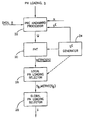
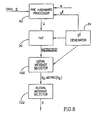
- FIG. 2 is a block diagram illustration of a pilot acquisition unit, constructed and operative in accordance with a preferred embodiment of the present invention
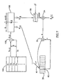
- FIG. 3 is a schematic illustration of a pre-Hadamard processor forming part of the pilot acquisition unit of FIG. 2;
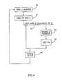
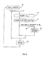
- FIG. 4 is a flow chart illustration of a method of operating the pre-Hadamard processor of FIG. 3 for signals with no frequency drift;
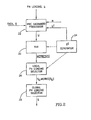
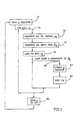
- FIG. 5 is a flow chart illustration of a method of operating the pre-Hadamard processor of FIG. 3 for signals with frequency drift;
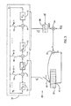
- FIG. 6 is a block diagram illustration of a decoder for data encoding with error correction codes, constructed and operative in accordance with a further preferred embodiment of the present invention
- FIG. 7 is a schematic illustration of a pre-Hadamard processor forming part of the unit of FIG. 6;
- FIG. 8 is a flow chart illustration of a method of operating the pre-Hadamard processor of FIG. 7 ;
- Appendix A provides the mathematical basis for the pre-Hadamard processor of FIGS. 2, 3 and 4 operating on quaternary phase shift keying (QPSK) signals having no frequency drift;
- QPSK quaternary phase shift keying
- Appendix B provides the mathematical basis for the pre-Hadamard processor of FIG. 5 operating on QPSK signals having an unknown frequency drift.
- Appendix C provides the mathematical basis for the pre-Hadamard processor of FIGS. 2, 3 and 4 operating on binary phase shift keying (BPSK) signals having no frequency drift;
- Appendix D provides the mathematical basis for the pre-Hadamard processor of FIG. 5 operating on BPSK signals having an unknown frequency drift.
- the pilot acquisition unit of the present invention considers each possible pseudo random number (PN) loading s (i.e. set of flip-flop values a i ) and determines the value of a metric, metric[s] for it.
- the present invention reviews the set of metrics[s] and selects the PN loading which is associated with the “best” (e.g. largest in absolute value) metric[s].
- the selected PN loading is the detected current PN loading of a PN generator on the transmitting unit with which the data was encoded.
- the complex PN sequence is generated by two PN generators, one for the in-phase sequence p l 0 [t] and one for the quaternary sequence p Q 0 [t].
- c t is the output of the in-phase PN generator and p l [t] is the in-phase portion of the complex QPSK PN sequence and is a function of the in-phase PN loading s.
- p Q 0 [t] is obtained from the estimated in-phase PN loading s.
- H m is the Hadamard matrix and u is the input vector to the fast Hadamard transform.
- the association of metrics[s] with the Hadamard matrix and the construction of the input vector u from the received samples are derived in detail in Appendix A for a CDMA, QPSK input pilot signal.
- Fast Hadamard transforms are discussed in the book Fast Transforms, Algorithms, Analysis, Applications , by D. F. Elliot and K. R. Rao, Academic Press, New York, 1982. The book is incorporated herein by reference.
- FIG. 2 illustrates, in block diagram format, the pilot acquisition unit of the present invention
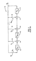
- FIG. 3 details a pre-Hadamard processor useful in the pilot acquisition unit of FIG. 2
- FIG. 4 illustrates, in flow-chart format, the method of operating the pre-Hadamard processor of FIG. 3 .
- the acquisition unit comprises a fast Hadamard transform (FHT) unit 20 , a pre-Hadamard processor 22 , a partial, possible PN loading s E generator 24 , a local PN loading selector 26 and a global PN loading selector 28 .
- FHT fast Hadamard transform
- Partial, possible PN loading s E generator 24 is typically a counter which provides the count value as the partial PN loading s E .
- pre-Hadamard processor 22 produces the Hadamard input vector u for all of the loadings s which have the current partial, possible loading s E in common, given the received data R[t] and an initial loading h of a PN generator 19 (FIG. 3) forming part of pre-Hadamard processor 22 .
- Initial loading h defined as (h M-1 , . . . h 0 ), is produced by providing the values of the taps 16 into their corresponding flip-flops 12 , where a 0 receives the value of h M-1 etc.
- FHT unit 20 performs a fast Hadamard transform on the Hadamard input signal u and produces therefrom the vector metrics[s] for all of the loadings s which have the current partial, possible loading s E in common.
- Local PN loading selector 26 selects the PN loading s l associated with the maximal component of
- IS-95 CDMA systems have two local PN generators, an in-phase PN generator and a quaternary PN generator, which are tied to each other and the in-phase PN generator influences the sequence of the quaternary PN generator. The opposite is not true.
- the local PN generators are initialized with their initial loadings and are stepped together until the in-phase PN generator achieves the selected loading s.
- the quaternary PN generator will have achieved its appropriate loading.
- pre-Hadamard processor 22 comprises a local pseudo-random number generator 19 , similar to PN generator 10 of FIG. 1, a Hadamard vector u register 30 , a summer 32 , a scalar multiplier 34 and a XOR-AND unit 36 .
- PN generator 19 is divided into two sections, an external section E of length M-Q incorporating the M-Q flip-flops 12 having values a 0 to a M-Q-1 and an internal section l of length Q incorporating the Q flip-flops 12 having values a M-Q to a M-1 .
- the internal section creates an internal vector g t l and the external section creates an external vector g t E where the vectors g are defined by:
- g t l (a M-1 . . . a M-Q )
- the vector g t (g t l ,g t E ) is one possible state of the local PN generator 19 while PN loading s is the PN loading with which the received pilot signal was generated. Furthermore, it will be appreciated that the output c t of the PN generator 19 is a function of the PN loadings s and g t as follows:
- ⁇ x,y > ( x 0 AND y 0 ) ⁇ ( x 1 AND y 1 ) ⁇ . . . ⁇ ( x n ⁇ 1 AND y n ⁇ 1 )
- the value of internal vector g t l defines an address within register 30 , where register 30 contains 2 Q memory cells. Arrow 40 which points from internal vector g t l to the address it defines, labeled 42 . Pre-Hadamard processor 22 removes the value stored in address 42 and provides the value to summer 32 .
- the external vector g t E is utilized, in combination with the possible, partial PN loading s E , to determine the sign of the datapoint R[t]. It is noted that a) the partial PN loading s E is of the same length M-Q as the external vector g t E and b) the external vector g t E and the partial PN loading s E are binary vectors of 1's and 0's. Specifically, the operation performed is:
- Scalar multiplier 34 multiplies the datapoint R[t] by the value of sign and the result is added, in summer 32 , to the component of the Hadamard input vector u removed from address 42 . The output of summer 32 is then inserted back into address 42 .
- pre-Hadamard processor 22 repeats the above-described operations for each of the N values of R[t]. Initially (steps 50 and 51 ), pre-Hadamard processor 22 zeros the Hadamard vector u register 30 and loads the PN generator 19 with its initial state vector h. In step 52 , pre-Hadamard processor 22 loops over the N values of R[t] where, for each value of R[t], the new value for the relevant component of u is determined (step 54 ) after which the PN generator 19 is stepped (step 56 ) to produce new values for internal vector g t l and external vector g t E .
- the u vector has been produced and, therefore, can be sent (step 58 ) to FHT unit 20 for determining the values of metrics[s].
- the process begins again at step 50 by resetting the Hadamard vector u and PN generator 19 to their initial states.
- FHT unit 20 operates once per partial PN loading s E while pre-Hadamard processor 22 repeats its operations N times per partial PN loading s E .
- the number of partial PN loadings s E is 2 M-Q where Q is chosen to balance between the number of operations performed by pre-Hadamard processor 22 and the number of operations performed by FHT unit 20 .
- the fast Hadamard transform performed by FHT unit 20 performs a series of addition operations only.
- the pilot acquisition unit of the present invention performs addition operations only (there are no real number multiplications since XOR-AND unit 36 performs only XOR-AND operations and scalar multiplier 34 only produces a sign change). Since the number of addition operations is relatively low, the pilot acquisition unit of the present invention performs the pilot synchronization operation faster than in the prior art. Just how much faster depends on the selection of Q.
- N 640 samples in the received signal R[t]
- the length M of the PN generators might be 15, and the split value Q might be 12.
- the relatively fast acquisition is particularly useful for CDMA systems, such as for cellular telephony, where initial synchronization needs to be acquired as quickly as possible.
- Equation 6 the equation for metric[s] given above in Equation 6 is valid only if there is no frequency drift in the received data R[t]. However, this is rarely the case. As discussed in Appendix B, the baseband down-conversion process is not ideal and some residual frequency drift will always be present (typically due to clock rate mismatch between the transmitter and receiver).
- L of differentials is a small, predetermined number.
- L is less than or equal to M but other values are possible.
- the multi-differential metric is determined in a manner similar to that of the non-frequency drift metric and thus, the pilot acquisition unit of FIG. 2 can be utilized to determine the PN loading associated with the best multi-differential metric.
- the pre-Hadamard processor 22 of FIG. 2 is operated in accordance with FIG. 5, to which reference is now made.
- FIG. 5 illustrates the operations of pre-Hadamard processor 22 per partial PN loading s E .
- pre-Hadamard processor 22 zeros the Hadamard vector u register 30 .
- pre-Hadamard processor 22 begins a loop 72 over the possible values of l.
- pre-Hadamard processor 22 For each value of l, pre-Hadamard processor 22 generates (step 74 ) the l-th input data loading ⁇ circumflex over (R) ⁇ l as per Equation 11.
- Pre-Hadamard processor 22 also generates (step 76 ) the l-th loading h l of PN generator 19 and loads it (step 78 ) into PN generator 19 .
- the l-th loading h l is defined by:
- Pre-Hadamard processor 22 determines the values of u register 30 in loop 80 as in the previous embodiment with the following exceptions:
- PN generator 19 is loaded with its l-th loading h l rather than h;
- u register 30 is updated (step 82 ) after which the PN generator 19 is stepped.
- the vector u stored in register 30 is provided (step 86 ) to FHT unit 20 .
- the remaining operations of the pilot acquisition unit are as before.
- Pre-Hadamard processor 22 repeats its operations per partial loading s E , local selector 26 selects the best solution s l per partial loading s E , and global selector 28 selects the best overall loading s.
- N 2560 samples in the received signal R[t]
- the length M of the PN generators might be 15
- the split value Q might be 12
- the number of differentials L might be 8.
- the pilot acquisition unit of the present invention can be utilized for systems with and without frequency drift, the only difference being the initial loading of the PN generator and the differential or non-differential input data. It is noted that all digital communication systems using PN generated codes, such as CDMA systems, other spread spectrum systems and systems which add error correcting codes to transmitted data, regardless of the format (QPSK, BPSK, etc.) of the transmitted data, typically have some frequency drift therein and thus, the second embodiment of FIG. 5 is typically applicable.
- the pilot acquisition unit of the present invention can be operated within a dual dwell scheme, as follows.
- the unit of FIG. 2 detects all PN loadings which produce a metric value (with or without frequency drift) above some pre-selected threshold.
- a further unit calculates the prior art metric defined either by Equation 4 (no frequency drift) or by Equation 5 (with frequency drift), where, in both, the signal p[t] is replaced by the signal p*[t] in order to deal with a QPSK signal.
- the threshold is determined as follows. Let the a-posteriori variance of the metric (given the data measurements) under a random loading be denoted by ⁇ 2 (each metric has its own value of ⁇ 2 ). At each dwell, only the hypotheses that are above t ⁇ (i.e.
- the first PN generator generates p t 0 [t].
- the second PN generator generates p Q 0 [t]. Both PN generators are initialized at the beginning of the transmission.
- the following non-linear mechanism is employed. Whenever the pattern 0,0,0,0,0,0,0,0,0,0,0,0,0,0,0,0,0,0,0,0,0,1 is detected in the first sequence, an additional 0 bit is inserted into the output of both sequences.
- the present invention does not collapse in the presence of the non-linearity but, instead, is degraded slightly.
- the present invention is not limited by what has been described hereinabove and that numerous modifications, all of which fall within the scope of the present invention, exist.
- the present invention has been described with respect to CDMA systems, it can be implemented in other digital communication systems.
- the present invention incorporates all implementations of code synchronization in the presence of frequency drifts, whether in conjunction with a pilot signal or not.
- FIGS. 6, 7 and 8 illustrate a decoder for messages encoded with error correcting codes which utilizes the concepts of the present invention.
- s be the message and let p[t] be the encoded version of the message s (of length M) which is the sequence to be transmitted.
- R[t] the received and sampled signal
- a generating matrix G with columns g t , is utilized, where:
- G [g l T . . . g t T . . . ]
- a value c t is a function of the message s and the t-th generating vector g t (of length M) and the sequence p[t] is produced from the value c t as follows:
- the sequence p[t] to be transmitted has the same structure as in the previous embodiments (see Equations 6 and 9) although it is formed from different components.
- FIG. 6 illustrates the decoder of the present invention for data encoded with error correcting codes. It has a similar structure to that of the pilot acquisition unit and thus, similar elements carry similar reference numerals.
- the decoder comprises FHT unit 20 , a pre-Hadamard processor, labeled 90 , partial, possible s E generator 24 , a local message selector 100 operating similarly to local PN loading selector 26 and a global message selector 102 operating similar to global PN loading selector 28 .
- pre-Hadamard processor 90 produces the Hadamard input vector u for all of the messages s which have the current partial, possible message s E in common, given the received data R[t].
- FHT unit 20 performs a fast Hadamard transform on the Hadamard input signal u and produces therefrom the vector metrics[s] for all of the messages s which, have the current partial, possible message s E in common.
- Local message selector 100 selects the message S l associated with the maximal component of
- FIG. 7 illustrates the pre-Hadamard processor 90 which is similar to pre-Hadamard processor 22 of FIG. 3 in that it comprises Hadamard vector u register 30 , summer 32 , scalar multiplier 34 and XOR-AND unit 36 .
- pre-Hadamard processor 90 comprises storage unit 104 , storing the generating vectors of generating matrix G and a XOR unit 106 instead of the local PN generator 19 of pre-Hadamard processor 22 .
- Storage unit 104 and XOR unit 106 together produce the internal and external vectors, labeled g t,l l and g t,l E respectively, which the Hadamard vector u register 30 and XOR-AND unit 36 require.
- XOR unit 106 generates a combination generating vector g t,l from two vectors g t and g t ⁇ l which are stored in the storage unit 104 .
- the latter vector is l vectors away from the former where l is as defined hereinbelow.
- the combination generating vector g t,l is divided into internal and external vectors, g t,l l and g t,l E , where the internal vector g t,l l contains Q components of the combination vector g t,l and the external vector g t,l E contains M-Q components of the combination vector g t,l .
- XOR-AND unit 36 combines the external vector g t,l E with the partial possible message s E , as described hereinabove in equation 10, and the multiplier 34 combines the result with the shifted received data ⁇ circumflex over (R) ⁇ l [t], defined hereinabove.
- internal vector g t,l l is utilized to define an address within register 30 . This is indicated by arrow 40 which points to the address, labeled 42 .
- Pre-Hadamard processor 90 removes the value stored in address 42 and provides the value to summer 32 .
- FIG. 8 illustrates the operations performed by pre-Hadamard processor 90 . They are similar to those shown in FIG. 5 except that the operations on a PN generator are replaced with those on the generating matrix G. Specifically, pre-Hadamard processor 90 begins by zeroing (step 70 ) the Hadamard vector u register 30 . Following the preparation of register 30 , pre-Hadamard processor 90 begins loop 72 over the possible values of l. For each value of l, pre-Hadamard processor 90 generates (step 74 ) the l-th input data loading ⁇ circumflex over (R) ⁇ l and generates (step 110 ) the combined generation vector g t,l using the current value of l.
- pre-Hadamard processor 90 Given combined generation vector g t,l , pre-Hadamard processor 90 then determines the values of u register 30 in loop 80 as discussed hereinabove and update u register 30 .
- the vector u stored in register 30 is provided (step 86 ) to FHT unit 20 .
- R[t] t . . . , ⁇ 2, ⁇ 1,0,1,2, . . . .
- R[t] consists of the following components:
- ⁇ l e j ⁇ l is the complex channel gain of the l-th finger
- F denotes the number of fingers
- ⁇ 0 denotes the residual frequency drift after baseband down-conversion.
- n[t] is a zero mean white noise term with variance ⁇ 2 .
- Equation 14 To calculate Equation 14 over all possible PN sequences p l [t], efficiently, we use a block-code soft decoding method, as follows hereinbelow.
- c t be the output bit produced by the PN generator or linear feedback shift (LFSR) at time t.
- LFSR linear feedback shift
- M [ h m - 1 1 0 ... 0 h m - 2 0 1 ... 0 ⁇ ⁇ ⁇ ⁇ h 1 0 ... 0 1 1 0 ... 0 0 ]
- a (t) a (t ⁇ 1) M
- a (t) (a 0 (t) a l (t) . . . a m ⁇ 1 (t) ) is the state of the shift register at time t.
- g t is the state of the Galois form LFSR after t clocks, when initialized by h.
- the Hadamard transform (HT) of u may be obtained from the HT-s of u 1,u 2 .
- Equation 15 can be recursively invoked on each of the smaller dimensional HT-s to produce the Fast Hadamard transform (FHT) algorithm.
- the system may be improved in terms of both computational time and memory requirements as follows. Let g t and s be partitioned as follows
- the received samples are subject to an unknown frequency drift (i.e., ⁇ 0 is non-zero).
- ⁇ [t] denotes the contribution of the noise terms.
- the approximation is due to the fact that the frequency drift is typically such that, for small l, ⁇ 0 l ⁇ 1.
- g t,l h l (M T ) t .
- the fast Hadamard transform routine needs to be applied only once, per each value of s E .
- the benefit of the multi-differential (over the differential) system is that a smaller amount of data is required.
- BPSK modulation utilizes a single binary sequence which results in a different metric. However, the derivation is similar, as will be discussed hereinbelow.
- Equation 3 (repeated here):
- the metric is maximized for
Abstract
Description


Claims (7)
Priority Applications (1)
| Application Number | Priority Date | Filing Date | Title |
|---|---|---|---|
| US09/583,898 US6788708B1 (en) | 1997-03-30 | 2000-06-01 | Code synchronization unit and method |
Applications Claiming Priority (4)
| Application Number | Priority Date | Filing Date | Title |
|---|---|---|---|
| IL12055597A IL120555A (en) | 1997-03-30 | 1997-03-30 | Code synchronization unit and method |
| IL120555 | 1997-03-30 | ||
| US08/869,728 US6163548A (en) | 1997-03-30 | 1997-06-05 | Code synchronization unit and method |
| US09/583,898 US6788708B1 (en) | 1997-03-30 | 2000-06-01 | Code synchronization unit and method |
Related Parent Applications (1)
| Application Number | Title | Priority Date | Filing Date |
|---|---|---|---|
| US08/869,728 Continuation US6163548A (en) | 1997-03-30 | 1997-06-05 | Code synchronization unit and method |
Publications (1)
| Publication Number | Publication Date |
|---|---|
| US6788708B1 true US6788708B1 (en) | 2004-09-07 |
Family
ID=32929454
Family Applications (1)
| Application Number | Title | Priority Date | Filing Date |
|---|---|---|---|
| US09/583,898 Expired - Fee Related US6788708B1 (en) | 1997-03-30 | 2000-06-01 | Code synchronization unit and method |
Country Status (1)
| Country | Link |
|---|---|
| US (1) | US6788708B1 (en) |
Cited By (3)
| Publication number | Priority date | Publication date | Assignee | Title |
|---|---|---|---|---|
| US20020015435A1 (en) * | 2000-07-31 | 2002-02-07 | Keith Rieken | Apparatus and method for configurable multi-dwell search engine for spread spectrum applications |
| US20110293062A1 (en) * | 2010-06-01 | 2011-12-01 | Ternarylogic Llc | Method and Apparatus for Rapid Synchronization of Shift Register Related Symbol Sequences |
| US10375252B2 (en) | 2010-06-01 | 2019-08-06 | Ternarylogic Llc | Method and apparatus for wirelessly activating a remote mechanism |
Citations (15)
| Publication number | Priority date | Publication date | Assignee | Title |
|---|---|---|---|---|
| US5056109A (en) * | 1989-11-07 | 1991-10-08 | Qualcomm, Inc. | Method and apparatus for controlling transmission power in a cdma cellular mobile telephone system |
| US5396516A (en) * | 1993-02-22 | 1995-03-07 | Qualcomm Incorporated | Method and system for the dynamic modification of control paremeters in a transmitter power control system |
| US5416797A (en) * | 1990-06-25 | 1995-05-16 | Qualcomm Incorporated | System and method for generating signal waveforms in a CDMA cellular telephone system |
| US5440597A (en) * | 1993-11-23 | 1995-08-08 | Nokia Mobile Phones Ltd. | Double dwell maximum likelihood acquisition system with continuous decision making for CDMA and direct spread spectrum system |
| US5463657A (en) * | 1994-02-15 | 1995-10-31 | Lockheed Missiles & Space Company, Inc. | Detection of a multi-sequence spread spectrum signal |
| WO1996010873A1 (en) | 1994-09-30 | 1996-04-11 | Qualcomm Incorporated | Multipath search processor for a spread spectrum multiple access communication system |
| US5548613A (en) * | 1993-12-30 | 1996-08-20 | Nec Corporation | DS/CDMA receiver using moving-averaged pilot signals for weighting and phase rotation of orthogonal data symbol vectors |
| US5550811A (en) * | 1993-12-30 | 1996-08-27 | Nec Corporation | Sync acquisition and tracking circuit for DS/CDMA receiver |
| US5577025A (en) * | 1995-06-30 | 1996-11-19 | Qualcomm Incorporated | Signal acquisition in a multi-user communication system using multiple walsh channels |
| US5579338A (en) * | 1992-06-29 | 1996-11-26 | Mitsubishi Denki Kabushiki Kaisha | Spread spectrum receiver using partial correlations |
| US5642377A (en) * | 1995-07-25 | 1997-06-24 | Nokia Mobile Phones, Ltd. | Serial search acquisition system with adaptive threshold and optimal decision for spread spectrum systems |
| US5767738A (en) * | 1996-10-21 | 1998-06-16 | Motorola, Inc. | Apparatus and method for demodulating a modulated signal |
| US5862190A (en) * | 1995-12-29 | 1999-01-19 | Motorola, Inc. | Method and apparatus for decoding an encoded signal |
| US5883889A (en) * | 1997-02-06 | 1999-03-16 | Northern Telecom Limited | Directional pseudonoise offset assignment in a CDMA cellular radiotelephone system |
| US6201799B1 (en) * | 1997-05-01 | 2001-03-13 | Lucent Technologies, Inc | Partial decorrelation for a coherent multicode code division multiple access receiver |
-
2000
- 2000-06-01 US US09/583,898 patent/US6788708B1/en not_active Expired - Fee Related
Patent Citations (16)
| Publication number | Priority date | Publication date | Assignee | Title |
|---|---|---|---|---|
| US5056109A (en) * | 1989-11-07 | 1991-10-08 | Qualcomm, Inc. | Method and apparatus for controlling transmission power in a cdma cellular mobile telephone system |
| US5416797A (en) * | 1990-06-25 | 1995-05-16 | Qualcomm Incorporated | System and method for generating signal waveforms in a CDMA cellular telephone system |
| US5841806A (en) * | 1990-06-25 | 1998-11-24 | Qualcomm Incorporated | Method and apparatus for the transmission of energy-scaled variable rate data |
| US5579338A (en) * | 1992-06-29 | 1996-11-26 | Mitsubishi Denki Kabushiki Kaisha | Spread spectrum receiver using partial correlations |
| US5396516A (en) * | 1993-02-22 | 1995-03-07 | Qualcomm Incorporated | Method and system for the dynamic modification of control paremeters in a transmitter power control system |
| US5440597A (en) * | 1993-11-23 | 1995-08-08 | Nokia Mobile Phones Ltd. | Double dwell maximum likelihood acquisition system with continuous decision making for CDMA and direct spread spectrum system |
| US5548613A (en) * | 1993-12-30 | 1996-08-20 | Nec Corporation | DS/CDMA receiver using moving-averaged pilot signals for weighting and phase rotation of orthogonal data symbol vectors |
| US5550811A (en) * | 1993-12-30 | 1996-08-27 | Nec Corporation | Sync acquisition and tracking circuit for DS/CDMA receiver |
| US5463657A (en) * | 1994-02-15 | 1995-10-31 | Lockheed Missiles & Space Company, Inc. | Detection of a multi-sequence spread spectrum signal |
| WO1996010873A1 (en) | 1994-09-30 | 1996-04-11 | Qualcomm Incorporated | Multipath search processor for a spread spectrum multiple access communication system |
| US5577025A (en) * | 1995-06-30 | 1996-11-19 | Qualcomm Incorporated | Signal acquisition in a multi-user communication system using multiple walsh channels |
| US5642377A (en) * | 1995-07-25 | 1997-06-24 | Nokia Mobile Phones, Ltd. | Serial search acquisition system with adaptive threshold and optimal decision for spread spectrum systems |
| US5862190A (en) * | 1995-12-29 | 1999-01-19 | Motorola, Inc. | Method and apparatus for decoding an encoded signal |
| US5767738A (en) * | 1996-10-21 | 1998-06-16 | Motorola, Inc. | Apparatus and method for demodulating a modulated signal |
| US5883889A (en) * | 1997-02-06 | 1999-03-16 | Northern Telecom Limited | Directional pseudonoise offset assignment in a CDMA cellular radiotelephone system |
| US6201799B1 (en) * | 1997-05-01 | 2001-03-13 | Lucent Technologies, Inc | Partial decorrelation for a coherent multicode code division multiple access receiver |
Non-Patent Citations (10)
| Title |
|---|
| A. J. Viterbi et al., "CDMA Principles of Spread Spectrum Communication", Addison-Wesley, 1995, section 3.4.3, pp. 58-59. |
| Douglas F. Elliott and K. Ramamohan Rao, "Fast Transforms, Algorithms, Analyses, Applications", Academic Press, New York, 1982, pp. 301-322. |
| International Search Report of International Application No. PCT/IL98/00067, dated Sep. 30, 1998. |
| Martin Cohn and Abraham Lempel, "On Fast M-Sequence Transforms", IEEE Transactions on Information Theory, 1977, pp.135-137. |
| Mohammad H. Zarrabizadeh and Elvino S. Sousa, "Analysis of a Differentially Coherent DS-SS Parallel Acquisition Receiver", IEEE Proceedings of the 45<th >Vehicular Technology Conference, vol. 2, 1995, pp. 271-275. |
| Mohammad H. Zarrabizadeh and Elvino S. Sousa, "Analysis of a Differentially Coherent DS-SS Parallel Acquisition Receiver", IEEE Proceedings of the 45th Vehicular Technology Conference, vol. 2, 1995, pp. 271-275. |
| Srdjan Z. Budisin, "Fast PN Sequence Correlation By Using PWT", IEEE Proceedings of the Mediterranean Electrotechnical Conference (MELECON), Lisbon, Portugal, Apr. 1989, pp. 513-515. |
| V. V. Losev and V. D. Dvornikov, "Recognition of Address Sequence Using Fast Transformations", Radio Engineering and Electronic Physics, vol. 28, No. 8, Aug. 1983, pp. 62-69. |
| V.V. Losev and V. D. Dvornikov, "Determination of the Phase of a Pseudorandom Sequence from its Segment Using Fast Transforms", Radio Engineering and Electronic Physics, vol. 26, No. 8, Aug. 1981, pp. 61-66. |
| Yair Be'ery and Jakov Snyders, "Optimal Soft Decision Block Decoders Based on Fast Hadamard Transform", IEEE Transactions o Information Theory, vol. 32, 1986, pp. 355-364. |
Cited By (6)
| Publication number | Priority date | Publication date | Assignee | Title |
|---|---|---|---|---|
| US20020015435A1 (en) * | 2000-07-31 | 2002-02-07 | Keith Rieken | Apparatus and method for configurable multi-dwell search engine for spread spectrum applications |
| US7003015B2 (en) * | 2000-07-31 | 2006-02-21 | Infineon Technologies Ag | Apparatus and method for configurable multi-dwell search engine for spread spectrum applications |
| US20110293062A1 (en) * | 2010-06-01 | 2011-12-01 | Ternarylogic Llc | Method and Apparatus for Rapid Synchronization of Shift Register Related Symbol Sequences |
| US8817928B2 (en) * | 2010-06-01 | 2014-08-26 | Ternarylogic Llc | Method and apparatus for rapid synchronization of shift register related symbol sequences |
| US9100166B2 (en) | 2010-06-01 | 2015-08-04 | Ternarylogic Llc | Method and apparatus for rapid synchronization of shift register related symbol sequences |
| US10375252B2 (en) | 2010-06-01 | 2019-08-06 | Ternarylogic Llc | Method and apparatus for wirelessly activating a remote mechanism |
Similar Documents
| Publication | Publication Date | Title |
|---|---|---|
| US5463657A (en) | Detection of a multi-sequence spread spectrum signal | |
| US7974413B2 (en) | Spread spectrum communications system and method utilizing chaotic sequence | |
| US8345725B2 (en) | Hidden Markov Model detection for spread spectrum waveforms | |
| US5963584A (en) | Direct sequence spread spectrum transmission process, with generation and optimization of sequences | |
| CN100397809C (en) | Pseudo-noise state generating device and method | |
| US6597726B2 (en) | Receiver including an apparatus for generating complex four-phase sequences | |
| US6163548A (en) | Code synchronization unit and method | |
| US7398287B2 (en) | Fast linear feedback shift register engine | |
| KR20000029073A (en) | Method and apparatus for generating multiple matched-filter vectors in a CDMA demodulator | |
| US8379689B2 (en) | Anti-jam communications having selectively variable peak-to-average power ratio including a chaotic constant amplitude zero autocorrelation waveform | |
| KR100470000B1 (en) | FREQUENCY TRACKING FOR COMMUNICATION SIGNALS USING M-ary ORTHOGONAL WALSH MODULATION | |
| US7352796B1 (en) | Multiple data rate complex Walsh codes for CDMA | |
| US6636549B1 (en) | Method for calculating phase shift coefficients of an M sequence | |
| Hong et al. | Performance evaluation of DS-CDMA system with M-ary orthogonal signaling | |
| JP3234202B2 (en) | Pseudo noise sequence output device, transmission device, reception device, communication system, pseudo noise sequence output method, transmission method, reception method, and information recording medium | |
| US7277382B1 (en) | Hybrid walsh encoder and decoder for CDMA | |
| JP3296341B2 (en) | Correlator | |
| US6788708B1 (en) | Code synchronization unit and method | |
| US20080198905A1 (en) | Method and Apparatus for Despread Data in Wireless Communication System | |
| US7042931B2 (en) | Path detection method and receiver | |
| KR960014408B1 (en) | Multi-access transmitter using prime code | |
| Rice | Sequence generation and detection for high data rate spread spectrum networks | |
| JPH07321703A (en) | Receiver, base station reception system and mobile station reception system | |
| JPH07321702A (en) | Receiver, base station reception system and mobile station reception system | |
| KR20120068999A (en) | Apparatus and method for generating the sequence family to spread the channel of communication system |
Legal Events
| Date | Code | Title | Description |
|---|---|---|---|
| AS | Assignment |
Owner name: D.S.P.C. TECHNOLOGIES LTD., ISRAEL Free format text: ASSIGNMENT OF ASSIGNORS INTEREST;ASSIGNORS:RAINISH, DORON;BEN-ELI, DAVID;BURSHTEIN, DAVID;AND OTHERS;REEL/FRAME:010868/0973;SIGNING DATES FROM 20000502 TO 20000515 |
|
| AS | Assignment |
Owner name: D.S.P.C. TECHNOLOGIES LTD., ISRAEL Free format text: CHANGE OF ADDRESS;ASSIGNOR:D.S.P.C. TECHNOLOGIES LTD.;REEL/FRAME:012252/0590 Effective date: 20011031 |
|
| AS | Assignment |
Owner name: INTEL CORPORATION, CALIFORNIA Free format text: ASSIGNMENT OF ASSIGNORS INTEREST;ASSIGNOR:D.S.P.C. TECHNOLOGIES LTD.;REEL/FRAME:014047/0317 Effective date: 20030501 |
|
| FEPP | Fee payment procedure |
Free format text: PAYER NUMBER DE-ASSIGNED (ORIGINAL EVENT CODE: RMPN); ENTITY STATUS OF PATENT OWNER: LARGE ENTITY Free format text: PAYOR NUMBER ASSIGNED (ORIGINAL EVENT CODE: ASPN); ENTITY STATUS OF PATENT OWNER: LARGE ENTITY |
|
| AS | Assignment |
Owner name: INTEL CORPORATION, CALIFORNIA Free format text: ASSIGNMENT OF ASSIGNORS INTEREST;ASSIGNOR:DSPC TECHNOLOGIES LTD.;REEL/FRAME:018505/0825 Effective date: 20061009 |
|
| FPAY | Fee payment |
Year of fee payment: 4 |
|
| FPAY | Fee payment |
Year of fee payment: 8 |
|
| REMI | Maintenance fee reminder mailed | ||
| LAPS | Lapse for failure to pay maintenance fees | ||
| STCH | Information on status: patent discontinuation |
Free format text: PATENT EXPIRED DUE TO NONPAYMENT OF MAINTENANCE FEES UNDER 37 CFR 1.362 |
|
| FP | Lapsed due to failure to pay maintenance fee |
Effective date: 20160907 |