US678081A - Multicylinder-motor. - Google Patents
Multicylinder-motor. Download PDFInfo
- Publication number
- US678081A US678081A US204600A US1900002046A US678081A US 678081 A US678081 A US 678081A US 204600 A US204600 A US 204600A US 1900002046 A US1900002046 A US 1900002046A US 678081 A US678081 A US 678081A
- Authority
- US
- United States
- Prior art keywords
- disk
- valve
- ports
- cylinders
- motor
- Prior art date
- Legal status (The legal status is an assumption and is not a legal conclusion. Google has not performed a legal analysis and makes no representation as to the accuracy of the status listed.)
- Expired - Lifetime
Links
- 239000012530 fluid Substances 0.000 description 9
- 230000009183 running Effects 0.000 description 4
- 230000000694 effects Effects 0.000 description 2
- 101100379079 Emericella variicolor andA gene Proteins 0.000 description 1
- 244000273618 Sphenoclea zeylanica Species 0.000 description 1
- 230000005540 biological transmission Effects 0.000 description 1
- 230000015572 biosynthetic process Effects 0.000 description 1
- 210000000038 chest Anatomy 0.000 description 1
- 239000002360 explosive Substances 0.000 description 1
- 210000002445 nipple Anatomy 0.000 description 1
- 239000007787 solid Substances 0.000 description 1
Images


Classifications
-
- F—MECHANICAL ENGINEERING; LIGHTING; HEATING; WEAPONS; BLASTING
- F01—MACHINES OR ENGINES IN GENERAL; ENGINE PLANTS IN GENERAL; STEAM ENGINES
- F01B—MACHINES OR ENGINES, IN GENERAL OR OF POSITIVE-DISPLACEMENT TYPE, e.g. STEAM ENGINES
- F01B1/00—Reciprocating-piston machines or engines characterised by number or relative disposition of cylinders or by being built-up from separate cylinder-crankcase elements
- F01B1/06—Reciprocating-piston machines or engines characterised by number or relative disposition of cylinders or by being built-up from separate cylinder-crankcase elements with cylinders in star or fan arrangement
- F01B1/0641—Details, component parts specially adapted for such machines
- F01B1/0668—Supporting and guiding means for the piston
Definitions
- This invention relates to an improved con-v struction of multicylinder-motors, as Well as valves specially adapted for multicylindermotors of the central-crankshaft and radiating-cylinder type suitable for motor-car and yacht propulsion, the objects being to secure a maximum effect, whilereducing the number of working parts and the size and Weight of the engine,to enable the motors to be readily reversed, and also to enable one ormore of the cylinders t0 be lput out of action while the remainder continue to run.
- crank-shaft or other expansible fluid the crank-shaft
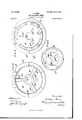
- Figure l is an end view of a six-cylinder en-v gine with a valve constructed according to this invention, one cylinder only being shown in the figure.
- Fig. 3 is an'elev'ation of'one end frame of the 1notor,showing the gear for cut-out disk.
- Fig. 6 is a face View ofr the4 inner cutout disk.
- Fig. 7 is a side view, half section half elevation, of the inner valve-seat disk.
- Figs. 8 and 9 are views of ⁇ the Vtwo faces ofv the same.
- Fig. 10 is a face view of the inner reversing-disk.
- Fig. 1l is a face view of the valve, and
- Fig. ⁇ 12 is a faceview of the outer Figs. 13 andl lt'are details showing the gear forl operating the eut-out and reversing disks, respectively.
- l illustrate aform vot' valve for an engine of the rotary-centralfcrank-shaf t and stationaryradialcylinder type having six Fig. 2 is a section on the linel ing connected theother.
- the G is a cylinder forming the frame ofthe engine.
- the cylinders G (of which vonly one is shown in Figs. 1 and 2) are six in'number and arranged radially around its circumference, three in one vert'icalplane and three in a parallel overlapping plane, so as to connect, respectively, with the cranks G2 G3 of the central rotary crank-shaft G4.
- the crankshaft is carried in bearings in covers or end frames G5 G6 of the cylinder G and is provided at one endwith a pinion Gto operate the valve through intermediate gearing, to be hereinafter described.
- the valve comprises four fixed members H H' and .l J', consisting of disk-like bodies having circumferential flanges, through which they are secured together by bolts H2, formto one crank-pin and threeto.
- valve-chest is fixed onto theend frame GG of the engine -by bolts G8,'passing through holes H3 inthelflange,H4 of the inner'member H.
- This inner member isshown in ⁇ sec- ,tion-in* Fig. 2, andface views are given in Figs. tand 5. Itis provided with three passages-H5 eachVA Aassage Communicating at one ,endby'a pipe H6 with one ofthe three cylinders whose pistons are connected With thel i l fV lcrank G2 and at the other end opens onto one face Offthenisk by portan7 rnl Harespec- A tively.
- the lmember H has also a central opening H10.
- Thejouter member or'cover H 'i is similar in arrangement to the inner-mem- ⁇ ber H, yj ust described, having three passages 9o i i H11, eac'licommunicatingat one-.end byak '1 pipe '(notshown) withoneofv-theth'ree t ⁇ :ylin" ⁇ .j derswhose pistons are connectedwithfvthel' t crank Gs andvopening atthe other b'y'ports'- f vI-l12 into the interior ofthe valve, thesepor'ts being placed impositionsv diametricallyy opposite to the ports of the member H.
- Thejouter member or'cover H 'i is similar in arrangement to the inner-mem- ⁇ ber H, yj ust described, having three passages 9o i i H11, eac'licommunicatingat one-.end byak '1 pipe '(notshown) withoneofv-
- the valve proper isplaced centrally within the valve-chest and consists of a, disk IM, Y
- 011e end M' is solid and carries a gear-wheel M2.
- the other end M8 is hollow, forming a communication with an internal chamber M4, which likewise opens onto each face of the disk through ports M5 M6.
- the disk pinor stem is rotatably carried in bushings J4 J5, fixed centrally on the disks J J', and its hollow end is preferably beveled and takes a bearing in the similarly-beveled end of the exhaust-pipe N, which passes through an opening H1 in the cover H' and is bolted by its flange N' onto the end ofV the projections in which the passages H11 are formed', thus leaving an annular communication through the opening H15 between the interior of the valve-chest and the atmosphere for a purpose to be presently described.
- rlfhe4 disk Mis likewise provided with a recess M7;
- TheV valve M is rotated by its gear-wheel M?, operated through intermediate gearing by the pinion G7 on the crank-shaft, sofas; to run athalf'- the speed and in. they rgeversedfirection to the rotation of the crankshaft.
- a convenient arrangement is that shewn inl Eig. 3, in which the pinion G7 gears withV a wheel- G, running idly on a pin G10, fixed on the ⁇ end frame G6.
- Each disk LL' is provided withV three delivery andsi@ exhaustports, being one delivery and two. ⁇
- Each disk is t is to say, one port is in the upper half and two ports in the lower half of the disk.
- valve-seat disks J J' Placed one on each side of the reversingdisks L L' are what I call the valve-seat disks J J', of which the iianges J2 J3 meet so as to form atight joint, forming, with the disk bodies, a chamber, within which the disksLL' are snugly but adj ustably fitted.
- the fiange J2 ofthe disk J is a broad flange at right angles to the disk body and forms the circumferential wall of the said chamber.
- an opening J5 formed, as shown in Figs. l andV 7, as a screwed nipple to enableiit to. be connected with the delivery-pipe from the source of the motive fiuid.
- .body of the disk J is provided with three chambersJ9J10J11. @Shown in dottedlinesin Figs. S and 9, ander-1e chamber-in section in l li'f.f.'7.. ⁇ ) ⁇ Eachch-amber opens onto the face adjoining the disk L by-four ports and onto the oppositeface. by one port, these latterbein-g
- Thedisk J' is furnished with similar chambers and ports arranged like those of disk J relatively to each other, but diametrically opposite relatively to ⁇ the body of the diskf-that is to say, onecham-ber, suchas J,v would be in the lower halt of the disk ⁇ and the oth'ertwo in the upperhalf.
- sien,and exhaust ofthe motive fluid to t beth ⁇ ⁇ setsrofmembers.
- the valve members 'H ICO and K K0 K7 of the disk K are opposite and form a communication between the three ports of each of the faces of said members.
- the two disks K and K are capable of rotation by the wheels K2 K3, fixed on the same rod K4.
- the rst'effect of rotating the rod so as to move the disk, Fig. 12, toward' the left will be to moveL the port K11, so as to shutoff communication between the passage H11, Fig.
- the reversing-disks L L' are placed so that the port L1 in their flanges is in connection with thede- -livery-pipe J5 and the motiverfl uid finds admittance to the annular space M8 and recess M7 of the rotating Valve M.
- the ports of the reversing disk K are so placed relatively to those on the adjoining face of the valve-seat disk J that eachof the entry-ports L8 L9 L10 and the exhaust-ports L11 L13 L15 arel over one of the outeror entry ports and one of the inner or delivery ports of each of the chambers J 0 J 11 J 10, respectively.
- the corresponding ports of the disks L and J are similarly placed relatively to each other.
- the rod L7 is used to rotate the disks L and L by their common gear-Wheel L0, so as to place each of the ports L8 L9 L10 of the disk L (and similarly the ports of the disk L) over the other outer or entry port of each of the chambers J9 J 10 J11 and place each of the exhaust ports L12 L14 L16 over an exhaustport leading to the said chambers.
- a further rotation of the disks L L willclose all the entry-ports, cutting off the supply of motive fluid to the motor.
- a multiple-cylinder motor the combination with the stationary valve-casing containing an inlet-port and the ports of feed andr exhaust passages communicating with all of the cylinders, of a valve between the said inlet IOO and said feed and exhaust ports, said valve being rotatory and governing the feed and l'exhaust of all of the cylinders, and a combined reversing and throttle disk between the said inlet and said feed and exhaust ports, said disk being rotatable on its axis to'control the direction of the motor and to stop the motor by cutting oft' the supply of motor fluid to the valve.
- a multi ple-cylinder motor the combination with the stationary valve-casing containing an inlet-port and the ports of feed and exhaust passages communicating with all of the cylinders, of a valve governing th'e feed andexhaust of all the cylinders, and a combined reversing and throttle disk rotatable on its axis to control the direction of the motor in two of its positions and in a third position to stop .the motor by cutting off the supply of motor fluid to the valve.
- a multiple-cylinder motor the combination with the stationary valve-casing containing an inlet-port and the ports of feed and exhaust passages communicating with all said cylinders, of a valve, a reversingdisk vand a cut-out disk, between the said inlet and said feed and exhaust ports, said valve being rotatory and governing the feed and exhaust of all the cylinders, said reversingdisk being rotatable on its axis to adjust it in two positions to control the direction of running of the motorand said cut-ont disk being rotatable on its axis to adjust it to suci cessively cut the cylinders in and cut them out, substantially as described.
- valve-disk In a multicylinder-motor, the combination of a rotating valve-disk, ports in said Valve-disk, a valve-seat having ports for each cylinder arranged to receive the motive iiuid ⁇ from two positions on its face and with two exhaust-ports for each cylinder on said face, and a reversing-disk placed between thevalvedisk and the valve-seat, supply and exhaust:
- ports foreach-cylinder in said reversing-disk and means for partially rotating said reversing-disk to adjust its ports relative to the ports of the valve-seat face to control the direction of run-ning ofthe motor, substantially as described.
- a stationary valve-seat disk a chamber for each cylinder in said disk, a plurality of ports for each chamber on one face of the said disk, a port for each chamber on the other face of the disk, a rotating valve-disk, ports in said rotating valve-disk, a reversingdisk placed between said valve-seat disk and the rotating valve, adjustable relatively to the valve-seat disk and ports in the reversingdisk for connecting the ports of the rotating valve-disk with ports of the valve-seat disk, Substantially as and for the purpose specified.
- a multicylinder-motor the combination of a stationary valve-seat disk, a chainber for each cylinder in said disk, a plurality of ports for each chamber on one face of the said disk,a port for each chamber on the other face of the disk, a rotating valve-disk, ports in said rotating valve-disk, a reversing-disk, placed between said valve-seat disk and the rotating valve, adjustable relatively to the valve-seat disk, and ports in the reversingdisk for connecting the ports of the rotating l valve-disk with ports of the valve-seat disk,
- valve-case wall ports in said wall,conduits leading from said ports yto the cylinders, a cut-out disk arranged between the said wall and the valve-seat disk, ports vin said cut-out disk and means for adjusting the said cntout disk, substantially as and for the purpose specified.
Landscapes
- Engineering & Computer Science (AREA)
- Mechanical Engineering (AREA)
- General Engineering & Computer Science (AREA)
- Multiple-Way Valves (AREA)
Description
No. 678,08l. Patented my 9, |901.
z. wln.
MULTICYLINDEB MOTOR. (Appucaion mea' Jan. is, 1900.) (No Model.) 6 Shoah-Sheet I.
MI/W M W/ff JLM @f2/M QM@ No. 678,081. Patented July 9, |90I.
Z. WIRT.
MULTICYLINDEB MUTUI?.A
(Application med Jan. 19, 1900.) (No Modell) 6 Sheets-Sheet 2.
fm/ www .By @M Q/W n onlus PETERS co mimo-LITRO.. WASHINGTON. D. c,
No. 678,0al. Patented luly 9, |961.
' z. wmT.
MULTICYLINDER MUTUI?.
(Application led Jan. 19, 1900.)
l54 Sheets-She 3.
(No Model.)
flac?,
Pa'tented luly 9, 190|.
No. 678,08l.
z. wmT. MULTIGYLINDER lMUTUI?.
- (Application led Jan. 19, 1900.)
(No Modem 6 Sheets-Sheet 4.
'mz Nonms mins ou., moro-Lyro.. WASHINGTON. D. c.
no. s7s,oa|. Patented July 9, Ism.l z. wm.
HULTICYLINDEB MOTOR.
(Application led im. 19, 1900.)
6 Shasta-Sheet v5.
(No Model.)l
. l fag/.5.
mi cams mus ou.. Fammi-[m4, wAsHmnTcn. o. c.
l Patented my 9, lem. j
6 Sheett-Shaet 6.
z. wm. l MULTICYLINDEB MOTOR.
(Application led In. 19, 1900.)
' No. mmm.I
(No Model.)
L7 ff W M J i UNVrTnD lSTATES Il?minimi. OFFICE.
ZEBULON WIRT, OF MONTICELLO, INDIANA.
MULTICYLINDERl-MOTOR.
SPECIFICATION forming part of Letters Patent No. 678,081, dated July 9, 1901.
I Application tiled January 19, 1900. Serial No. 2,016. (No model.)
To ctZZ whom t may concern."
Be it known that LZEBULON VVIRT, a citi- 'zen of the United States of America, residingv This invention relates to an improved con-v struction of multicylinder-motors, as Well as valves specially adapted for multicylindermotors of the central-crankshaft and radiating-cylinder type suitable for motor-car and yacht propulsion, the objects being to secure a maximum effect, whilereducing the number of working parts and the size and Weight of the engine,to enable the motors to be readily reversed, and also to enable one ormore of the cylinders t0 be lput out of action while the remainder continue to run.
In motors of the type above referred to the cylinders, preferablythree or more in number, are arranged radially around a vcommon central crank-shaft, and by the successive or alternate admission of an explosive gas,steam,`
or other expansible fluid the crank-shaft,
which is provided with suitable gear for' the` transmission of power or maybe coupled ydi rect, is caused to rotate.
Figure l is an end view of a six-cylinder en-v gine with a valve constructed according to this invention, one cylinder only being shown in the figure.
9 9 of Fig. `1. Fig. 3 is an'elev'ation of'one end frame of the 1notor,showing the gear for cut-out disk.
y cylinders and two cranks', three cylinders beoperatingthe valve. Figs. 4 and ishowy the two faces of the inner member of the valvechest. Fig. 6 is a face View ofr the4 inner cutout disk. Fig. 7 is a side view, half section half elevation, of the inner valve-seat disk.
Figs. 8 and 9 are views of` the Vtwo faces ofv the same. Fig. 10 is a face view of the inner reversing-disk. Fig. 1l is a face view of the valve, and Fig.`12 is a faceview of the outer Figs. 13 andl lt'are details showing the gear forl operating the eut-out and reversing disks, respectively.
In the figures l illustrate aform vot' valve for an engine of the rotary-centralfcrank-shaf t and stationaryradialcylinder type having six Fig. 2 is a section on the linel ing connected theother.
G is a cylinder forming the frame ofthe engine. The cylinders G (of which vonly one is shown in Figs. 1 and 2) are six in'number and arranged radially around its circumference, three in one vert'icalplane and three in a parallel overlapping plane, so as to connect, respectively, with the cranks G2 G3 of the central rotary crank-shaft G4. p The crankshaft is carried in bearings in covers or end frames G5 G6 of the cylinder G and is provided at one endwith a pinion Gto operate the valve through intermediate gearing, to be hereinafter described.
The valve comprises four fixed members H H' and .l J', consisting of disk-like bodies having circumferential flanges, through which they are secured together by bolts H2, formto one crank-pin and threeto.
'voll ing the valve-chest, and four adjustable' i;
flanged disks K K and L L andone rotatable disk M, constituting the valve. proper contained Within the chest thus formed.v
The valve-chest is fixed onto theend frame GG of the engine -by bolts G8,'passing through holes H3 inthelflange,H4 of the inner'member H. This inner member isshown in `sec- ,tion-in* Fig. 2, andface views are given in Figs. tand 5. Itis provided with three passages-H5 eachVA Aassage Communicating at one ,endby'a pipe H6 with one ofthe three cylinders whose pistons are connected With thel i l fV lcrank G2 and at the other end opens onto one face Offthenisk by portan7 rnl Harespec- A tively. The lmember H has also a central opening H10. Thejouter member or'cover H 'i is similar in arrangement to the inner-mem-` ber H, yj ust described, having three passages 9o i i H11, eac'licommunicatingat one-.end byak '1 pipe '(notshown) withoneofv-theth'ree t`:ylin"` .j derswhose pistons are connectedwithfvthel' t crank Gs andvopening atthe other b'y'ports'- f vI-l12 into the interior ofthe valve, thesepor'ts being placed impositionsv diametricallyy opposite to the ports of the member H. The
member Hand cover H'are pi'ovidediwith- *i flan ges H13 H14, respectively, which are jointed to the iianges J2 Js of the valve-seat disks J J by the through-'bolts Ilz-,before referred to.
`Ice
y The valve proper isplaced centrally within the valve-chest and consists of a, disk IM, Y
(shown in section, Fig. 2,' face view, Fig. `11,
carried on a central pin or stem, of which 011e end M' is solid and carries a gear-wheel M2. The other end M8 is hollow, forming a communication with an internal chamber M4, which likewise opens onto each face of the disk through ports M5 M6. The disk pinor stem is rotatably carried in bushings J4 J5, fixed centrally on the disks J J', and its hollow end is preferably beveled and takes a bearing in the similarly-beveled end of the exhaust-pipe N, which passes through an opening H1 in the cover H' and is bolted by its flange N' onto the end ofV the projections in which the passages H11 are formed', thus leaving an annular communication through the opening H15 between the interior of the valve-chest and the atmosphere for a purpose to be presently described. rlfhe4 disk Mis likewise provided with a recess M7;
TheV valve M is rotated by its gear-wheel M?, operated through intermediate gearing by the pinion G7 on the crank-shaft, sofas; to run athalf'- the speed and in. they rgeversedfirection to the rotation of the crankshaft. A convenient arrangement is that shewn inl Eig. 3, in which the pinion G7 gears withV a wheel- G, running idly on a pin G10, fixed on the` end frame G6. The `wheel G9 gearswith al wheel G11, running idly on a` pin G12, secured to the frame Gf6 at one end, the other end bet ing supported in a hole in a` boss.V Ifl11fon.the faceof the valve member LI. formed integral withY the wheel G11 is. al: gea-. wheel G13, which gears. with, the valvesteui wheel M2. d 1
Placed one on` each sidevofl the-valvefdisk-- M are the reversing-disks. L L', whichf moveA together and form the reverser for changing the direction of runninglofthe motor. These disks are rotatably carried en the/bnshingvJ and valve-stein M11,respectivelbn,andgolneface1 of each disk has a werking bearing Withtheadjoining face ofthe valve. Mg. provided with a fiangeLz. These meeteach other at theiredges, so as to-formfatight joint, thus. constituting a closed-*chamber,A within,V
which the valve M revolves, angann ularspacel M8 being left between the 'periphery-ot the able opening` being provided intherflangerJ? to permit. of the said engagement. Each disk LL' is provided withV three delivery andsi@ exhaustports, being one delivery and two.`
exhaust port-s vfor each cylinder.' The a r 1 1Supposdng that allthe cylinders are desired torun, thecut-out disks KA K' are placed with rangement ofi'` these ports in the disk; Ii, is, shownin Fig. l0, the delivery b eiinglettered` L8 L1 L10 and the exhaust L11 to. L11,respecf tively. The arrangement of thepOItsin the disk L' is. similar, relatively to each other, but,thedelivery-ports are diametrically op, posite relatively to the toothed segment-that Secured 'te 0.1
Each disk is t is to say, one port is in the upper half and two ports in the lower half of the disk.
Placed one on each side of the reversingdisks L L' are what I call the valve-seat disks J J', of which the iianges J2 J3 meet so as to form atight joint, forming, with the disk bodies, a chamber, within which the disksLL' are snugly but adj ustably fitted. The fiange J2 ofthe disk J is a broad flange at right angles to the disk body and forms the circumferential wall of the said chamber. In the side of thisfiange is an opening J5, formed, as shown in Figs. l andV 7, as a screwed nipple to enableiit to. be connected with the delivery-pipe from the source of the motive fiuid. The
.body of the disk J is provided with three chambersJ9J10J11. @Shown in dottedlinesin Figs. S and 9, ander-1e chamber-in section in l li'f.f.'7..`)` Eachch-amber opens onto the face adjoining the disk L by-four ports and onto the oppositeface. by one port, these latterbein-g Thedisk J' is furnished with similar chambers and ports arranged like those of disk J relatively to each other, but diametrically opposite relatively to` the body of the diskf-that is to say, onecham-ber, suchas J,v would be in the lower halt of the disk` and the oth'ertwo in the upperhalf.
Afs. seen inFgig. 2, the flanges Llilandi-imapd Jia-nd Ij1111r1eet,A so as to ferml tight join-ts, constituting, with their respective bodies, two chambers, within which are placed the adL justabl-ejdisks-K lrespectively, whichrnove togetherand:` form a cutout forv cuttingeut the cylinders inl succession, as many as desiredy. 'lille faces of each disk have a working bearing with the facesof theadiiOinlng valvemembers,A and the periphery of each disk is 'mot-hed.. the;- teeth engaging, vespe@- ti,vely,with.gear-wheelsK2 K3, fixed ou one red;
K1, carriedinbeariugs in the langes H15, J 2, and,- Hf11, Eig. 1.3i Suitable openings. are providedinY the fianges H13 and H11 to permitgof said engagements.
'lllierdisk- K islprovided with ports arranged asshown in- Fig. 1 3, K5 K6 K7 being delivery and K8 K1 'K10 vent ports, The disk K' likewisehassii;` ports, K11 K12 K13 being delivery and K11 K`15=K111 vent ports, Fig. 12.
Frein theiabove descriptionv it `will be gath ered that; theythree cylinders eonnectedwith one: crank are, operated through those t members` of. the.- valve wfliichareonone side ofthe revolving; disk M, and the other three cylindersiby thoseon, the other side, the disk M 4beiimg ccunmonte and controlling theadmis.-
sien,and; exhaust ofthe motive fluid to t beth` `setsrofmembers.
'.llheoperationot the valve is as follows:
their ports arranged in the position shown iu Figs. 2,6, and l2 relatively to the ports of thefadjacenttfaces. ot' the valve members 'H ICO and K K0 K7 of the disk K are opposite and form a communication between the three ports of each of the faces of said members. As before described, the two disks K and K are capable of rotation by the wheels K2 K3, fixed on the same rod K4. The rst'effect of rotating the rod so as to move the disk, Fig. 12, toward' the left will be to moveL the port K11, so as to shutoff communication between the passage H11, Fig. 2, and the corresponding port of the disk J'-that is, the connection between the Valve and one cylinder of the motorbut open communication through the port K14 between the said cylinder and the atmosphere through the central opening H5 of the cover H1, so that while the cylinder is cut off from receivingr any supply of motive fluid the formation of pressure or vacuum within it is prevented. in like manner shuts off in succession the remaining two cylinders, which receive the fluid through the cover H', and then in succession those which are connected with the passages in the inner member H, the ventports Ks K0 K10 giving communication with the atmosphere through the central opening H10 of the member When the disks K K are in their normal position, therefore, there is free connection between the th ree passages H5, leading to the cylinders, and the ports J6 J7 J8 of the valve-face disk J, and also between the corresponding ports of the disk J and the passages H11 in the cover H', leading to the other three cylinders. If, now, it is desired to run so as to revolve the crank-shaft fromright to left, (when looking at Fig. 1,) the reversing-disks L L' are placed so that the port L1 in their flanges is in connection with thede- -livery-pipe J5 and the motiverfl uid finds admittance to the annular space M8 and recess M7 of the rotating Valve M. At the same time the ports of the reversing disk K are so placed relatively to those on the adjoining face of the valve-seat disk J that eachof the entry-ports L8 L9 L10 and the exhaust-ports L11 L13 L15 arel over one of the outeror entry ports and one of the inner or delivery ports of each of the chambers J 0 J 11 J 10, respectively. The corresponding ports of the disks L and J are similarly placed relatively to each other. As the valve M revolves from left to right (it will be remembered that the valve rotates in an opposite direction to the crank-shaft) its recess M7 successively uncovers the ports L8 L0 L10 and admits the motive fluid through their respective chambers, ports- J0 J1 J8, K5 K0 K7, and H Hs H0, passages H5, and pipes H0 to the three cylinders connected with the crankshaft Gz. The exhaust fluid returns by the same ports to the chambers of the valve-seat disk J and then pass by the respective exhaust-ports to the exhaust-port M6 of the valve M, from which it passes through the chamber M4 and hollow stem M3 to the exhaust-pipe N. The cylinders connected to the crank-shaft G3 are supplied and exhausted in a similar manner through the ports and passages of the Continued rotation of the rodV valve members L', J', K', and Hl', which, it
vwill be remembered, are arranged similarly relatively to each other. If, now, it be desired to reverse the engine, the rod L7 is used to rotate the disks L and L by their common gear-Wheel L0, so as to place each of the ports L8 L9 L10 of the disk L (and similarly the ports of the disk L) over the other outer or entry port of each of the chambers J9 J 10 J11 and place each of the exhaust ports L12 L14 L16 over an exhaustport leading to the said chambers. A further rotation of the disks L L willclose all the entry-ports, cutting off the supply of motive fluid to the motor.
. The arrangement of cylinders described in connection with Figs. l and 2 possesses particular advantages. By providing the multiple cylinders in two circumferential parallel series with the members ofthe series alternating with each other and with pistons equal in number and weight connected with oppositely-disposed cranks an equilibrium is main tained which reduces vibration to the minimum and enables the provision of a large number of cylinders of large ldiameter within a comparatively small compass.
What I claim as new, and desire tol secure by4 Letters Patent, is
l. In a multiple-cylinder motor, the combination with the stationary valve-casing containing an inlet-port and the ports of feed andr exhaust passages communicating with all of the cylinders, of a valve between the said inlet IOO and said feed and exhaust ports, said valve being rotatory and governing the feed and l'exhaust of all of the cylinders, and a combined reversing and throttle disk between the said inlet and said feed and exhaust ports, said disk being rotatable on its axis to'control the direction of the motor and to stop the motor by cutting oft' the supply of motor fluid to the valve.
2. In a multi ple-cylinder motor, the combination with the stationary valve-casing containing an inlet-port and the ports of feed and exhaust passages communicating with all of the cylinders, of a valve governing th'e feed andexhaust of all the cylinders, and a combined reversing and throttle disk rotatable on its axis to control the direction of the motor in two of its positions and in a third position to stop .the motor by cutting off the supply of motor fluid to the valve.
3. In a multiple-cylinder motor, the'combination with a stationary valve-casing containing an inlet-port and the ports of feed and exhaust passages communicating with all of the cylinders, of a valve movable to govern the feed and exhaust of all of the cylinders, a cut-out disk movable to successively cut the cylinders in and cut them out, and acombined reversing and throttle disk movable to control the direction of the motor and to stop the motor. v
4. In a multiple-'cylinder motor, the combination with the stationary valve-casing con- IIO taining an inlet-port and the ports of feed and exhaust passages communicating with all said cylinders, of a valve and a cut-out disk between the said inlet and said feed andA exhaust ports, said valve being rotatory and governing the feed and exhaust of all the cylinders and said cut-out disk being rotatable on its axis to adjust it to successively cut the cylinders in and cut them out, substantially as described.
5. In a multiple-cylinder motor, the combination with the stationary valve-casing containing an inlet-port and the ports of feed and exhaust passages communicating with all said cylinders, of a valve, a reversingdisk vand a cut-out disk, between the said inlet and said feed and exhaust ports, said valve being rotatory and governing the feed and exhaust of all the cylinders, said reversingdisk being rotatable on its axis to adjust it in two positions to control the direction of running of the motorand said cut-ont disk being rotatable on its axis to adjust it to suci cessively cut the cylinders in and cut them out, substantially as described.
6. In a multicylinder-motor, the combination of a rotating valve-disk, ports in said Valve-disk, a valve-seat having ports for each cylinder arranged to receive the motive iiuid` from two positions on its face and with two exhaust-ports for each cylinder on said face, and a reversing-disk placed between thevalvedisk and the valve-seat, supply and exhaust:
ports foreach-cylinder in said reversing-disk, and means for partially rotating said reversing-disk to adjust its ports relative to the ports of the valve-seat face to control the direction of run-ning ofthe motor, substantially as described.
`7. In a multicylinder-motor, the combinaeri-3,081
tion of a stationary valve-seat disk, a chamber for each cylinder in said disk, a plurality of ports for each chamber on one face of the said disk, a port for each chamber on the other face of the disk, a rotating valve-disk, ports in said rotating valve-disk, a reversingdisk placed between said valve-seat disk and the rotating valve, adjustable relatively to the valve-seat disk and ports in the reversingdisk for connecting the ports of the rotating valve-disk with ports of the valve-seat disk, Substantially as and for the purpose specified.
8. In a multicylinder-motor, the combination of a stationary valve-seat disk, a chainber for each cylinder in said disk, a plurality of ports for each chamber on one face of the said disk,a port for each chamber on the other face of the disk, a rotating valve-disk, ports in said rotating valve-disk, a reversing-disk, placed between said valve-seat disk and the rotating valve, adjustable relatively to the valve-seat disk, and ports in the reversingdisk for connecting the ports of the rotating l valve-disk with ports of the valve-seat disk,
a valve-case wall, ports in said wall,conduits leading from said ports yto the cylinders, a cut-out disk arranged between the said wall and the valve-seat disk, ports vin said cut-out disk and means for adjusting the said cntout disk, substantially as and for the purpose specified.
In testimony whereof I have signed my naine to this Vspecification in the presence of two subscribing witnesses.
ZEBULON WIRT.
Witnesses:
J. W. DYRENFORTH, F. J. MARTIN.
Priority Applications (1)
| Application Number | Priority Date | Filing Date | Title |
|---|---|---|---|
| US204600A US678081A (en) | 1900-01-19 | 1900-01-19 | Multicylinder-motor. |
Applications Claiming Priority (1)
| Application Number | Priority Date | Filing Date | Title |
|---|---|---|---|
| US204600A US678081A (en) | 1900-01-19 | 1900-01-19 | Multicylinder-motor. |
Publications (1)
| Publication Number | Publication Date |
|---|---|
| US678081A true US678081A (en) | 1901-07-09 |
Family
ID=2746628
Family Applications (1)
| Application Number | Title | Priority Date | Filing Date |
|---|---|---|---|
| US204600A Expired - Lifetime US678081A (en) | 1900-01-19 | 1900-01-19 | Multicylinder-motor. |
Country Status (1)
| Country | Link |
|---|---|
| US (1) | US678081A (en) |
-
1900
- 1900-01-19 US US204600A patent/US678081A/en not_active Expired - Lifetime
Similar Documents
| Publication | Publication Date | Title |
|---|---|---|
| US668878A (en) | Rotary engine. | |
| US674258A (en) | Rotary engine. | |
| US658556A (en) | Rotary engine or motor. | |
| US678081A (en) | Multicylinder-motor. | |
| US706320A (en) | Steam-engine. | |
| US782954A (en) | Rotary valve. | |
| US377143A (en) | Rotary steam-engine | |
| US361598A (en) | Half to damas ltjtz | |
| US729313A (en) | Valve-gear. | |
| US651157A (en) | Fluid-pressure motor. | |
| US394684A (en) | Rotary engine | |
| US98619A (en) | Improvement in rot art engines | |
| US602630A (en) | Rotary engine | |
| US683619A (en) | Rotary engine. | |
| US757300A (en) | Rotary fluid-motor. | |
| US646419A (en) | Rotary engine. | |
| US652317A (en) | Rotary engine. | |
| US1298098A (en) | Internal-combustion engine. | |
| US428656A (en) | Half to daniel scull | |
| US776336A (en) | Multiple-cylinder engine. | |
| US632816A (en) | Rotary engine. | |
| US1157684A (en) | Rotary valve. | |
| US687822A (en) | Rotary engine. | |
| US1254219A (en) | Engine. | |
| US980449A (en) | Hydraulic engine. |