US6768319B2 - Adaptive compensation of measurement error for industrial process control transmitters - Google Patents
Adaptive compensation of measurement error for industrial process control transmitters Download PDFInfo
- Publication number
- US6768319B2 US6768319B2 US10/192,339 US19233902A US6768319B2 US 6768319 B2 US6768319 B2 US 6768319B2 US 19233902 A US19233902 A US 19233902A US 6768319 B2 US6768319 B2 US 6768319B2
- Authority
- US
- United States
- Prior art keywords
- capacitance
- sensors
- sensor
- tilde over
- ratio
- Prior art date
- Legal status (The legal status is an assumption and is not a legal conclusion. Google has not performed a legal analysis and makes no representation as to the accuracy of the status listed.)
- Expired - Lifetime, expires
Links
- 238000005259 measurement Methods 0.000 title claims abstract description 74
- 238000004519 manufacturing process Methods 0.000 title claims abstract description 33
- 230000003044 adaptive effect Effects 0.000 title description 3
- 238000000034 method Methods 0.000 claims abstract description 63
- 239000003990 capacitor Substances 0.000 claims abstract description 42
- 230000014509 gene expression Effects 0.000 claims abstract description 19
- 230000005284 excitation Effects 0.000 claims description 20
- 230000010354 integration Effects 0.000 claims description 9
- 238000004364 calculation method Methods 0.000 description 5
- 238000010586 diagram Methods 0.000 description 5
- 238000005070 sampling Methods 0.000 description 4
- 238000012937 correction Methods 0.000 description 3
- 238000004891 communication Methods 0.000 description 2
- 230000000694 effects Effects 0.000 description 2
- 238000007689 inspection Methods 0.000 description 2
- 238000004458 analytical method Methods 0.000 description 1
- 230000005540 biological transmission Effects 0.000 description 1
- 238000009530 blood pressure measurement Methods 0.000 description 1
- 238000002474 experimental method Methods 0.000 description 1
- 238000011065 in-situ storage Methods 0.000 description 1
- 239000000463 material Substances 0.000 description 1
- 239000002184 metal Substances 0.000 description 1
- 238000010606 normalization Methods 0.000 description 1
- 230000000737 periodic effect Effects 0.000 description 1
- 238000012360 testing method Methods 0.000 description 1
Images


Classifications
-
- G—PHYSICS
- G01—MEASURING; TESTING
- G01D—MEASURING NOT SPECIALLY ADAPTED FOR A SPECIFIC VARIABLE; ARRANGEMENTS FOR MEASURING TWO OR MORE VARIABLES NOT COVERED IN A SINGLE OTHER SUBCLASS; TARIFF METERING APPARATUS; MEASURING OR TESTING NOT OTHERWISE PROVIDED FOR
- G01D5/00—Mechanical means for transferring the output of a sensing member; Means for converting the output of a sensing member to another variable where the form or nature of the sensing member does not constrain the means for converting; Transducers not specially adapted for a specific variable
- G01D5/12—Mechanical means for transferring the output of a sensing member; Means for converting the output of a sensing member to another variable where the form or nature of the sensing member does not constrain the means for converting; Transducers not specially adapted for a specific variable using electric or magnetic means
- G01D5/14—Mechanical means for transferring the output of a sensing member; Means for converting the output of a sensing member to another variable where the form or nature of the sensing member does not constrain the means for converting; Transducers not specially adapted for a specific variable using electric or magnetic means influencing the magnitude of a current or voltage
- G01D5/24—Mechanical means for transferring the output of a sensing member; Means for converting the output of a sensing member to another variable where the form or nature of the sensing member does not constrain the means for converting; Transducers not specially adapted for a specific variable using electric or magnetic means influencing the magnitude of a current or voltage by varying capacitance
-
- G—PHYSICS
- G01—MEASURING; TESTING
- G01R—MEASURING ELECTRIC VARIABLES; MEASURING MAGNETIC VARIABLES
- G01R31/00—Arrangements for testing electric properties; Arrangements for locating electric faults; Arrangements for electrical testing characterised by what is being tested not provided for elsewhere
- G01R31/28—Testing of electronic circuits, e.g. by signal tracer
- G01R31/282—Testing of electronic circuits specially adapted for particular applications not provided for elsewhere
- G01R31/2829—Testing of circuits in sensor or actuator systems
Definitions
- This invention relates to capacitive pressure sensors for use in industrial process control systems, and particularly to compensation of measurement error due to leakage conductance in such sensors.
- Certain industrial process control transmitters employ capacitive pressure sensors and measurement circuits that measure industrial process variables.
- the measurement circuit includes a sigma-delta charge-to-digital converter and a processor that supplies the measurement value of the process variable for transmission to a central control station.
- the sensor includes a metal diaphragm that serves as a common electrode for a differential pair of capacitive sensors. Different portions of the process variable are applied to opposite sides of the diaphragm to deflect the diaphragm based on the process variable.
- the capacitive sensors are charged by an input voltage, and the charge is transferred to the measurement circuit to derive the digital representation of the value of the process variable.
- the sigma-delta circuit integrates the charges to increase or decrease an output signal over a number of sample cycles.
- the ratio of the number of steps of increase or decrease to the total number of samples represents the process variable value.
- leakage conductance generates measurement errors.
- Two common sources of leakage conductance include conductance across the sensor capacitor terminals, such as through a dielectric fill material (e.g., oil), and residual moisture on the circuit board forming the measurement circuit.
- a leakage resistance of about 1 gigaOhm conductance as small as about 1 nanoSiemen degrades the accuracy of a 16-bit digital signal to about 13 bits. Even where the excitation of the capacitive sensor is symmetric, the finite leakage still causes significant measurement error.
- the present invention is directed to adaptive compensation of measurement error in industrial process control transmitters by which the process variable measurement value is corrected for error due to leakage based on the measured capacitance and leakage conductance of the sensor.
- an industrial process control transmitter is operated to compensate for errors in a process variable measurement due to leakage conductance in the transmitter.
- the industrial process control transmitter includes first and second capacitive sensors that sense the process variable and a measurement circuit coupled to the sensors that provides the process variable measurement based on ratio of the capacitance, e.g., C H - C L C H + C L
- C H and C L are the first and second capacitors.
- a leakage conductance is measured for each of the first and second sensors.
- the process variable measurement is derived from the capacitance ratio and leakage conductances.
- first and second capacitance deviations are identified for each of the first and second sensors based on the measured leakage conductance.
- First and second error expressions are derived based on ratios of the capacitance deviations to the total capacitance of the sensor.
- the process variable measurement is derived from the measured capacitance ratio and the first and second error expressions.
- ⁇ m is the measured capacitance ratio
- the corrected process variable measurement is calculated as ⁇ m + ⁇ 1 ⁇ 2 .
- the values for the capacitance deviations are calculated during manufacture and stored in the processor for calculation of the corrected measurement.
- the processor includes a look-up table that contains values of the deviation capacitances based on various sample frequencies and/or measured conductance of the sensor.
- FIGS. 1-5 are circuit diagrams and accompanying waveforms useful in explaining the principles of the present invention.
- FIG. 6 is a block diagram illustrating an industrial process control transmitter employing the present invention.
- FIG. 1 is a circuit diagram illustrating a sensor 100 , charge circuit 102 and first stage of an integrator circuit 104 employed in an industrial process control transmitter.
- Sensor 100 includes a capacitive sensor C S coupled between differential amplifier 10 of a first-stage sigma-delta ( ⁇ - ⁇ ) integrator 104 and the charge circuit 102 that includes a source of excitation voltage V P and V N .
- Switches 12 and 14 couple sources V P and V N to an input side of sensor capacitor C S .
- the opposite side of capacitor C S is selectively coupled through switch 16 to voltage V mid , selected halfway between voltages V P and V N , and through switch 18 to the negative input of differential amplifier 10 .
- Switches 12 , 14 , 16 and 18 are operated to conductive and non-conductive states during non-overlapping phases ⁇ 1 and ⁇ 2 .
- the circuit operates in a positive and a negative excitation mode.
- voltage source V N is coupled through switch 14 to the input of capacitive sensor C S and the output of capacitive sensor C S is coupled to V mid through switch 16 .
- voltage source V P is coupled through switch 12 to the input of sensor C S and the output of sensor C S is coupled through switch 18 to the negative input of differential amplifier 10 .
- voltage source V P is coupled through switch 12 to the input of capacitive sensor C S and the output of capacitive sensor C S is coupled to V mid through switch 16 .
- phase ⁇ 2 voltage source V N is coupled through switch 14 to the input of sensor C S and the output of sensor C S is coupled through switch 18 to the negative input of differential amplifier 10 .
- Integrator feedback capacitor C F is coupled between the output and negative input of amplifier 10 .
- the excitation voltage V ex jumps from the low level V N to the high level V P
- the sensor excitation voltage V ex jumps from the high level V P to the low level V N .
- V ex is the magnitude of the excitation voltage. If the leakage conductance is not zero, current will flow from V P through switch 12 , the sensor leakage resistance R S , and switch 18 to amplifier 10 . The magnitude of this leakage current is V P /R S , where V P is the voltage difference between input voltage V P and the voltage V mid . If the settling time for the integrator is negligible or small compared to the integrator duration ⁇ , then the total charge leaked from source V P into the integrator is approximated as ⁇ V P /R S .
- ⁇ C S V P V ex ⁇ ⁇ R S .
- ⁇ C S V N V ex ⁇ ⁇ R S
- V mid is the voltage difference between node V mid and input voltage V N .
- V mid may be ground or zero voltage and V P and V N symmetrical about ground as positive and negative voltages.
- FIGS. 2 and 3 illustrate waveforms demonstrating the effect of non-zero leakage conductance in the sensor.
- the output voltage may deviate by ⁇ V due to leakage conductance.
- the effect of leakage conductance is equivalent to a deviation of the sensor capacitive value ⁇ C S .
- the equivalent capacitance deviation changes with the operating frequency of the sensor. For example, if the operating frequency is 25 kHz, the sampling period is 40 ⁇ sec and the integration duration, ⁇ , is 20 ⁇ sec. Table 1 identifies the equivalent capacitive deviation due to leakage for various leakage conductances.
- Table 2 illustrates the equivalent capacitance deviation for various leakage conductances where the operating frequency is 62.5 kHz, the sampling period is 16 ⁇ sec and the integration duration, ⁇ , is 8 ⁇ sec.
- both sensors can be operated using the same symmetrical excitation voltages.
- FIG. 4 illustrates a simplified circuit diagram of the sensor 100 , charge circuit 102 and a first stage of an integrator circuit 104 for an industrial process control transmitter employing a differential pressure sensor.
- the circuit operates similar to that of FIG. 1, except there are separate differentially-operated capacitive sensors measuring the high-side (C H ) and low-side (C L ) of the process variable.
- ⁇ 1 and ⁇ 2 represent non-overlapping phase signals
- y and ⁇ overscore (y) ⁇ are complimentary signals representing whether the circuit is operating in the positive or negative excitation mode at the particular sampling period.
- phase ⁇ 2 the input of high-side capacitor C H is coupled through switch 14 to V N and the output of high-side capacitor C H is coupled through switch 18 to the negative input of differential amplifier 10 .
- ⁇ C H is the equivalent capacitance deviation of the high-side capacitance C H due to high-side leakage conductance
- ⁇ C L is the equivalent capacitive deviation of low-side capacitor C L due to low-side leakage conductance.
- the equivalent capacitance deviation and measurement errors can be calculated from the measured leakage conductance across the sensor capacitors.
- modulation frequency of a second order capacitance-to-digital modulator is assumed to be 25 kHz.
- the error in the count, ⁇ N, due to leakage conductance can be as much as 973 counts in 2 16 total counts (N). This represents an error of as much as 1.5% in the measurement value.
- FIG. 5 illustrates sensor 100 , charge circuit 102 and first integrator stage 104 of an industrial process control transmitter incorporating a capacitance sensor having offset compensation capacitors as described in U.S. Pat. No. 6,295,875 granted Oct. 2, 2001 to Frick et al. for “Process Pressure Measurement Devices with Improved Error Compensation” and assigned to the same Assignee as the present invention.
- the sensor described in the Frick et al. patent employs offset capacitors that are subject to the same process variables as the corresponding principal capacitive sensors.
- the offset capacitors which are in the form of rings, provide compensation due to offset of the principal capacitive sensors.
- the gain factors k H and k L are within the dynamic range of about 0.39 to 0.55.
- Non-zero leakage conductance may exist across both the principal capacitive sensors as well as the offset ring capacitors.
- the equivalent capacitive deviation and measurement errors of the sensor with offset capacitors can be calculated from the measured leakage conductance across the ring capacitors and the principal capacitive sensors.
- the direction of the capacitive shift caused by leakage can be positive or negative.
- ⁇ H G HR /G H
- the high-side principal capacitive sensor leakage conductance is G H
- the high-side offset capacitor leakage conductance G HR .
- ⁇ 0 ⁇ C H - ⁇ C L C H + C L ⁇ ⁇ m ⁇ ⁇ c , ( 10 )
- the inputs to the compensated measurement algorithm are (1) the measured capacitance ratio ⁇ m , (2) the total sensor capacitances, C H +C L , and (3) the measured leakage conductances G H and G L .
- the output of the algorithm is the compensated capacitance ratio ⁇ mc ⁇ m + ⁇ 1 ⁇ 2 .
- Tables 6, 7 and 8 set forth three examples of application of the compensation algorithm to the sensor illustrated in FIG. 4; these examples parallel those set forth in Tables 3, 4 and 5, respectively.
- Table 3 sets forth the results of the case of a zero differential process variable having the same parameters employed in the example of Table 3.
- the sample frequency is 25 kHz
- C H 50 pF
- C L 50 pF
- leakage conductance is between 10 ⁇ 7 and 10 ⁇ 9 siemens, depending on capacitance deviation.
- the measured capacitance ratio ⁇ m and the calculated error terms ⁇ 1 and ⁇ 2 are identified.
- the compensated capacitor ratio ⁇ mc is derived from ⁇ m + ⁇ 1 ⁇ 2 .
- Table 7 sets forth the case of a non-zero differential variable where C H and C L are 75 pH and 25 pF, respectively, and the base capacitance ratio ⁇ O is 0.5, using the same parameters as the example of Table 4.
- the calculated error terms ⁇ 1 and ⁇ 2 and compensated capacitance ratio ⁇ mc ⁇ m + ⁇ 1 ⁇ 2 and identified.
- Table 8 tabulates the case of a non-zero differential pressure where the base capacitance ratio ⁇ 0 is ⁇ 0.5, using the same parameters set forth above where ⁇ C H and ⁇ C L are the equivalent capacitance deviations caused by leakage (see Table 5).
- the error terms ⁇ 1 , ⁇ 2 from which compensated measurement result ⁇ mc are tabulated in Table 8.
- the compensation equation is derived as
- the inputs for the compensation algorithm are the measured capacitance ratio ⁇ m , the total estimated active sensor capacitance ⁇ tilde over (C) ⁇ H + ⁇ tilde over (C) ⁇ L and the measured leakage conductances G H , G HR , G L and G LR .
- the equivalent capacitance deviations ⁇ tilde over (C) ⁇ H , ⁇ tilde over (C) ⁇ HR , ⁇ tilde over (C) ⁇ L and ⁇ tilde over (C) ⁇ LR and the error values ⁇ tilde over ( ⁇ ) ⁇ 1 , ⁇ tilde over ( ⁇ ) ⁇ 2 and ⁇ tilde over ( ⁇ ) ⁇ are intermediate calculations of the algorithm, and the compensated reading of ⁇ tilde over ( ⁇ ) ⁇ mc ⁇ tilde over ( ⁇ ) ⁇ m + ⁇ tilde over ( ⁇ ) ⁇ 1 ⁇ tilde over ( ⁇ ) ⁇ 2 output of the algorithm is obtained.
- FIG. 6 is a block diagram of an industrial process control transmitter in which the present invention is useful.
- the industrial process control transmitter includes sensor 100 , charge circuit 102 , ⁇ - ⁇ converter 104 as herein described operating processor 106 that includes look-up table 108 to supply measurement data to transceiver 110 .
- Communication link 112 couples the transceiver of the industrial process control transmitter to central control station 114 .
- communication link 112 may be a two-wire loop that supplies power and control signals from the control station to the transmitter and supplies data to the control station from the transmitter.
- One well-known two-wire link is a 4-20 mA loop operating in a digital or analog mode (or both).
- the leakage conductance of each sensor capacitor is measured during manufacture of the transmitter, such as during final inspection in the factory.
- V ex V P ⁇ V N
- V P is the voltage difference between the node V P and the node V mid
- V N is the voltage difference between the node V N and the node V mid
- ⁇ is the integration time
- C F is the capacitance of the feedback capacitor. Therefore the values of the capacitance deviations, ⁇ C H and ⁇ C L , can be calculated at the final inspection and stored in look-up table 108 of processor 106 . If the transmitter is designed to operate at various sample frequencies, such as 25 kHz and 62.5 kHz, the values of the capacitance deviations, ⁇ C H and ⁇ C L , can be stored in look-up table 108 and retrieved for use by the processor on the basis of the sample frequency.
- the conductance of the sensor might be measured in situ, such as by applying a test voltage to the capacitive sensors during a start-up mode, or during a periodic interruption of sensor operation, to measure the leakage current, thus obtaining the leakage conductance.
- table 108 contains a table of values of the capacitance deviations for various values of leakage conductance (or current) and values of sampling frequency, as applicable. The measured conductance (and operating sample frequency, if applicable) is used to look up values of capacitance deviation for correction of the measurement.
- the capacitance deviations for the symmetrical differential sensor exemplified in FIG. 5 are identified in a similar manner.
- processor 106 calculates the error values ⁇ 1 and ⁇ 2 using the retrieved values of high-side and low-side capacitance deviations, the total (rated) capacitance of the sensor and the measured ratio ⁇ m .
- the present invention thus provides a simple and effective technique for correction of errors in measurement output values due to leakage conductance in industrial process control transmitters.
- output values provide a more accurate measurement of process variables than can be achieved without the correction technique.
- the technique can be programmed into the processor using values established at the time of manufacture of the transmitter, or the values may be stored in a look-up table for the processor's use based on variations in sample frequency and/or leakage conductance of the transmitter.
Landscapes
- Physics & Mathematics (AREA)
- General Physics & Mathematics (AREA)
- Measurement Of Resistance Or Impedance (AREA)
Abstract
Error in a process variable measurement due to leakage conductance in an industrial process control transmitter is compensated by identifying capacitance deviations δCH and δCL based on leakage conductance for each of the capacitive sensors. Error expressions are derived as 
and 
where ηm is the measured capacitance ratio based on 
The corrected process variable measurement is calculated as ηm+ε1−ε2. A look-up table is employed in some embodiments to correlate the capacitance deviations to sample frequency and/or measured leakage conductance. Application of the technique to sensors employing offset capacitors that compensate for offset of the capacitive sensors is also described.
Description
This invention relates to capacitive pressure sensors for use in industrial process control systems, and particularly to compensation of measurement error due to leakage conductance in such sensors.
Certain industrial process control transmitters employ capacitive pressure sensors and measurement circuits that measure industrial process variables. The measurement circuit includes a sigma-delta charge-to-digital converter and a processor that supplies the measurement value of the process variable for transmission to a central control station. In some embodiments, the sensor includes a metal diaphragm that serves as a common electrode for a differential pair of capacitive sensors. Different portions of the process variable are applied to opposite sides of the diaphragm to deflect the diaphragm based on the process variable. The capacitive sensors are charged by an input voltage, and the charge is transferred to the measurement circuit to derive the digital representation of the value of the process variable.
The sigma-delta circuit integrates the charges to increase or decrease an output signal over a number of sample cycles. The ratio of the number of steps of increase or decrease to the total number of samples represents the process variable value.
One problem with sensors of the class describe above is that leakage conductance generates measurement errors. Two common sources of leakage conductance include conductance across the sensor capacitor terminals, such as through a dielectric fill material (e.g., oil), and residual moisture on the circuit board forming the measurement circuit. Experiments reveal that a leakage resistance of about 1 gigaOhm (conductance as small as about 1 nanoSiemen) degrades the accuracy of a 16-bit digital signal to about 13 bits. Even where the excitation of the capacitive sensor is symmetric, the finite leakage still causes significant measurement error.
The present invention is directed to adaptive compensation of measurement error in industrial process control transmitters by which the process variable measurement value is corrected for error due to leakage based on the measured capacitance and leakage conductance of the sensor.
In one embodiment of the invention, an industrial process control transmitter is operated to compensate for errors in a process variable measurement due to leakage conductance in the transmitter. The industrial process control transmitter includes first and second capacitive sensors that sense the process variable and a measurement circuit coupled to the sensors that provides the process variable measurement based on ratio of the capacitance, e.g., 
where CH and CL are the first and second capacitors. A leakage conductance is measured for each of the first and second sensors. The process variable measurement is derived from the capacitance ratio and leakage conductances.
In preferred embodiments, first and second capacitance deviations, δCH and δCL, are identified for each of the first and second sensors based on the measured leakage conductance. First and second error expressions are derived based on ratios of the capacitance deviations to the total capacitance of the sensor. The process variable measurement is derived from the measured capacitance ratio and the first and second error expressions.
In some embodiments, the first error expression is 
and the second error expression is 
where ηm is the measured capacitance ratio, and the corrected process variable measurement is calculated as ηm+ε1−ε2.
In some embodiments the values for the capacitance deviations are calculated during manufacture and stored in the processor for calculation of the corrected measurement. In other embodiments, the processor includes a look-up table that contains values of the deviation capacitances based on various sample frequencies and/or measured conductance of the sensor.
FIGS. 1-5 are circuit diagrams and accompanying waveforms useful in explaining the principles of the present invention.
FIG. 6 is a block diagram illustrating an industrial process control transmitter employing the present invention.
1. Circuit Model.
FIG. 1 is a circuit diagram illustrating a sensor 100, charge circuit 102 and first stage of an integrator circuit 104 employed in an industrial process control transmitter. Sensor 100 includes a capacitive sensor CS coupled between differential amplifier 10 of a first-stage sigma-delta (Σ-Δ) integrator 104 and the charge circuit 102 that includes a source of excitation voltage VP and VN. Switches 12 and 14 couple sources VP and VN to an input side of sensor capacitor CS. The opposite side of capacitor CS is selectively coupled through switch 16 to voltage Vmid, selected halfway between voltages VP and VN, and through switch 18 to the negative input of differential amplifier 10. Switches 12, 14, 16 and 18 are operated to conductive and non-conductive states during non-overlapping phases Φ1 and Φ2.
The circuit operates in a positive and a negative excitation mode. For the positive excitation mode, during phase Φ1, voltage source VN is coupled through switch 14 to the input of capacitive sensor CS and the output of capacitive sensor CS is coupled to Vmid through switch 16. During phase Φ2, voltage source VP is coupled through switch 12 to the input of sensor CS and the output of sensor CS is coupled through switch 18 to the negative input of differential amplifier 10. For the negative excitation mode, during phase Φ1, voltage source VP is coupled through switch 12 to the input of capacitive sensor CS and the output of capacitive sensor CS is coupled to Vmid through switch 16. During phase Φ2, voltage source VN is coupled through switch 14 to the input of sensor CS and the output of sensor CS is coupled through switch 18 to the negative input of differential amplifier 10. Integrator feedback capacitor CF is coupled between the output and negative input of amplifier 10.
In the case of positive excitation, the excitation voltage Vex jumps from the low level VN to the high level VP, whereas for case of negative excitation, the sensor excitation voltage Vex jumps from the high level VP to the low level VN.
If the leakage conductance is zero (ideal conditions), the voltage step created in the integrator output for each sample during the positive excitation mode is 
and the voltage step created in the integrator output for each sample during the negative excitation mode is 
where Vex is the magnitude of the excitation voltage. If the leakage conductance is not zero, current will flow from VP through switch 12, the sensor leakage resistance RS, and switch 18 to amplifier 10. The magnitude of this leakage current is VP/RS, where VP is the voltage difference between input voltage VP and the voltage Vmid. If the settling time for the integrator is negligible or small compared to the integrator duration τ, then the total charge leaked from source VP into the integrator is approximated as τVP/RS. The integrator duration τ is based on the sample frequency (e.g., 
where fS is the sample frequency). This leaked charge generates an additional voltage deviation in the integrator output, which is expressed as 
Therefore, the effective voltage step for the positive excitation case is expressed as 
where the second term, δCS, contributed by non-zero leakage conductance, can be expressed as 
A similar analysis can be applied for the negative excii3ation case, resulting in an effective voltage step expressed as 
where the second term, δCS, introduced by non-zero leakage conductance, can be expressed as 
and VN is the voltage difference between node Vmid and input voltage VN. As in the case of phase Φ1, Vmid may be ground or zero voltage and VP and VN symmetrical about ground as positive and negative voltages.
FIGS. 2 and 3 illustrate waveforms demonstrating the effect of non-zero leakage conductance in the sensor. As shown in FIGS. 2 and 3, the output voltage may deviate by δV due to leakage conductance. In both the positive and negative excitation cases, the effect of leakage conductance is equivalent to a deviation of the sensor capacitive value δCS.
The equivalent capacitance deviation changes with the operating frequency of the sensor. For example, if the operating frequency is 25 kHz, the sampling period is 40 μsec and the integration duration, τ, is 20 μsec. Table 1 identifies the equivalent capacitive deviation due to leakage for various leakage conductances.
| TABLE 1 |
| Equivalent Capacitance Deviation at 25 kHz |
| Gs (1/Ω) | δCs (pF) | ||
| 10−9 | 0.01 | ||
| 10−8 | 0.1 | ||
| 10−7 | 1.0 | ||
| 10−6 | 10.0 | ||
Table 2 illustrates the equivalent capacitance deviation for various leakage conductances where the operating frequency is 62.5 kHz, the sampling period is 16 μsec and the integration duration, τ, is 8 μsec.
| TABLE 2 |
| Equivalent Capacitance Deviation at 62.5 kHz |
| Gs (1/Ω) | δCs (pF) | ||
| 10−9 | 0.004 | ||
| 10−8 | 0.04 | ||
| 10−7 | 0.4 | ||
| 10−6 | 4.0 | ||
2. Measurement Error.
In the case of an industrial process control transmitter having a differential sensor employing high-side CS and low-side CL capacitive sensors, both sensors can be operated using the same symmetrical excitation voltages.
FIG. 4 illustrates a simplified circuit diagram of the sensor 100, charge circuit 102 and a first stage of an integrator circuit 104 for an industrial process control transmitter employing a differential pressure sensor. The circuit operates similar to that of FIG. 1, except there are separate differentially-operated capacitive sensors measuring the high-side (CH) and low-side (CL) of the process variable. In this case, Φ1 and Φ2 represent non-overlapping phase signals, and y and {overscore (y)} are complimentary signals representing whether the circuit is operating in the positive or negative excitation mode at the particular sampling period. Thus, during the positive excitation mode of the circuit (y is high), input voltage VN is coupled through switch 14 during phase Φ1 to the input side of low-side sensor CL, and the output side is coupled to Vmid through switch 20. During phase Φ2 input voltage VP is supplied to the input side of low-side sensor CL and the output side is coupled through switch 22 to the negative input of differential amplifier 10. In a similar manner during the negative excitation mode of the circuit ({overscore (y)} is high), during phase Φ1 the input of high-side sensor CH is coupled through switch 12 to input voltage VP and the output of high-side capacitor is coupled through switch 16 to voltage Vmid. During phase Φ2 the input of high-side capacitor CH is coupled through switch 14 to VN and the output of high-side capacitor CH is coupled through switch 18 to the negative input of differential amplifier 10. The process variable under measurement by the circuit illustrated in FIG. 4 is, in the ideal situation without leakage conductance, expressed as a capacitance ratio 
However, non-zero leakage conductance affects the actual capacitance ratio. Consequently, the actual (measured) capacitance ratio is 
where δCH is the equivalent capacitance deviation of the high-side capacitance CH due to high-side leakage conductance and δCL is the equivalent capacitive deviation of low-side capacitor CL due to low-side leakage conductance. The measurement error of the circuit illustrated in FIG. 4 is expressed as 
The equivalent capacitance deviation and measurement errors can be calculated from the measured leakage conductance across the sensor capacitors. Tables 3, 4 and 5 set forth three examples of capacitive deviations and the corresponding measurement errors induced by leakage conductance and also identifies the measurement error ΔN in the digital count,based on a normalization count of N=216. In each case, modulation frequency of a second order capacitance-to-digital modulator is assumed to be 25 kHz. The leakage conductance varies between 10−7 and 10−9 siemens as set forth in Table 1. Tn the example given in Table 3, the high-side capacitance GH and the low-side capacitance CL are both 50 pP and the capacitance ratio under measurement is 0 (η0=0), representing a zero differential capacitance.
| TABLE 3 |
| Leakage induced measurement error |
| δCH (pF) | δCL (pF) | ηm | ε | ΔN |
| 0 | 0 | 0.0 | 0 | 0 |
| 0.01 | 0 | 0.00010 | 0.00010 | 7 |
| 0.1 | 0 | 0.00100 | 0.00100 | 65 |
| 1.0 | 0 | 0.00990 | 0.00990 | 649 |
| 0 | 0.01 | −0.00010 | −0.00010 | −7 |
| 0 | 0.1 | −0.00100 | −0.00100 | −65 |
| 0 | 1.0 | −0.00990 | −0.00990 | −649 |
| CH = 50 pF, | ||||
| CL = 50 pF, | ||||
| η0 = 0 | ||||
In a second example, set forth in Table 4, the circuit is operated in a non-zero differential input (η0=0.5), the high-side capacitance is CH=75 pF and the low-side capacitance is CL=25 pF.
| TABLE 4 |
| Leakage induced measurement error |
| δCH (pF) | δCL (pF) | ηm | ε | ΔN |
| 0 | 0 | 0.5 | 0 | 0 |
| 0.01 | 0 | 0.50005 | 0.00005 | 3 |
| 0.1 | 0 | 0.50050 | 0.00050 | 33 |
| 1.0 | 0 | 0.50495 | 0.00495 | 324 |
| 0 | 0.01 | 0.49985 | −0.00015 | −10 |
| 0 | 0.1 | 0.49850 | −0.00150 | −98 |
| 0 | 1.0 | 0.48515 | −0.01485 | −973 |
| CH = 75 pF, | ||||
| CL = 25 pF, | ||||
| η0 = 0.5 | ||||
In another non-zero differential input example (η0=−0.5), the high-side capacitor is CH=25 pF and the low-side capacitance is CL=75 pF and the results set forth in Table 5.
| TABLE 5 |
| Leakage induced measurement error |
| δCH (pF) | δCL (pF) | ηm | ε | ΔN |
| 0 | 0 | −0.5 | 0 | 0 |
| 0.01 | 0 | −0.49985 | 0.00015 | 10 |
| 0.1 | 0 | −0.49850 | 0.00150 | 98 |
| 1.0 | 0 | −0.48515 | 0.01485 | 973 |
| 0 | 0.01 | −0.50005 | −0.00005 | −3 |
| 0 | 0.1 | −0.50050 | −0.00050 | −33 |
| 0 | 1.0 | −0.50495 | −0.00495 | −324 |
| CH = 25 pF, | ||||
| CL = 75 pF, | ||||
| η0 = −0.5 | ||||
As demonstrated by the tabulated results, the error in the count, ΔN, due to leakage conductance can be as much as 973 counts in 216 total counts (N). This represents an error of as much as 1.5% in the measurement value.
FIG. 5 illustrates sensor 100, charge circuit 102 and first integrator stage 104 of an industrial process control transmitter incorporating a capacitance sensor having offset compensation capacitors as described in U.S. Pat. No. 6,295,875 granted Oct. 2, 2001 to Frick et al. for “Process Pressure Measurement Devices with Improved Error Compensation” and assigned to the same Assignee as the present invention. The sensor described in the Frick et al. patent employs offset capacitors that are subject to the same process variables as the corresponding principal capacitive sensors. The offset capacitors, which are in the form of rings, provide compensation due to offset of the principal capacitive sensors. More particularly, separate offset capacitors CHR and CLR provide compensation for offset of the corresponding principal capacitor CH and CL, respectively. The process variable measurement is given by the capacitance ratio expression: 
where {tilde over (C)}H and {tilde over (C)}L are the total capacitance of the high-side and low-side principal capacitive sensors such that {tilde over (C)}H=CH−kHCHR and {tilde over (C)}L=CL−kLCLR, and kH and kL are gain factors associated with the corresponding offset capacitor CHR and CLR. Typically, the gain factors kH and kL are within the dynamic range of about 0.39 to 0.55. Non-zero leakage conductance may exist across both the principal capacitive sensors as well as the offset ring capacitors. Consequently, the actual capacitance ratio measurement is 
where the equivalent capacitance deviations δ{tilde over (C)}H and δ{tilde over (C)}L for the high-side and low-side sensors can be expressed as δ{tilde over (C)}H=δCH−kHδCHR and δ{tilde over (C)}L=δCL−kLδCLR, and where δCH and δCL are the equivalent capacitive deviations of the principal capacitive sensors induced by leakage and δCHR and δCLR are the equivalent capacitive deviations of the offset capacitors induced by leakage. Consequently, the measurement error is 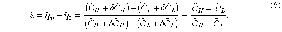
Similar to the case of FIG. 4, the equivalent capacitive deviation and measurement errors of the sensor with offset capacitors can be calculated from the measured leakage conductance across the ring capacitors and the principal capacitive sensors.
The direction of the capacitive shift caused by leakage can be positive or negative. For example, the normalized equivalent capacitance deviation for the high-side capacitor is δ{tilde over (C)}H=(1−kHβH){circumflex over (V)}xGHτ where βH=GHR/GH, the high-side principal capacitive sensor leakage conductance is GH, and the high-side offset capacitor leakage conductance is GHR. There are three possible conditions: If kHβH=1, then δ{tilde over (C)}H=0 and the active capacitance shift caused by the principal sensor leakage conductance is cancelled by that of the offset leakage conductance. If kHβH>1, then δ{tilde over (C)}H<0 and the high-side active capacitance shift caused by leakage conductance is negative. If kHβH<1, then δ{tilde over (C)}H>0 and the high-side active capacitance shift caused by leakage conductance is positive. Similar conditions exist for the low-side sensor.
3. Adaptive Compensation Algorithm.
In the case of the circuit illustrated in FIG. 4, the leakage conductance is very small, so the effective capacitive deviation caused by leakage conductance is small compared to the sensor capacitance. Consequently, δCH<<CH and δCL<<CL. Using a first order approximation, the error calculation can be expressed as follows: 
Consequently a compensated measurement equation can be derived based on the error expression of equation (7):
where ε1 and ε2 are 
Hence, the process variable measurement can be expressed as 
and is approximately equal to the measured capacitance ratio adjusted for the two error expressions, ε1−ε2.
The inputs to the compensated measurement algorithm are (1) the measured capacitance ratio ηm, (2) the total sensor capacitances, CH+CL, and (3) the measured leakage conductances GH and GL. The algorithm calculates the equivalent capacitance deviations δCH and δCL, as well as error calculations ε1 and ε2 and ε=ε2−ε1. The output of the algorithm is the compensated capacitance ratio ηmc≈ηm+ε1−ε2.
Tables 6, 7 and 8 set forth three examples of application of the compensation algorithm to the sensor illustrated in FIG. 4; these examples parallel those set forth in Tables 3, 4 and 5, respectively. Table 3 sets forth the results of the case of a zero differential process variable having the same parameters employed in the example of Table 3. The sample frequency is 25 kHz, CH=50 pF, CL=50 pF and leakage conductance is between 10−7 and 10−9 siemens, depending on capacitance deviation. The measured capacitance ratioηm and the calculated error terms ε1 and ε2 are identified. The compensated capacitor ratio ηmc is derived from ηm+ε1−ε2.
| TABLE 6 |
| Compensated Capacitive Ratio |
| ηmc = ηm + | |||||
| ηm | δCH (pF) | δCL (pF) | ε1 | ε2 | ε1 − ε2 |
| 0.00010 | 0.01 | 0 | 0 | 0.00010 | 0.0 |
| 0.00100 | 0.1 | 0 | 0 | 0.00100 | 0.0 |
| 0.00990 | 1.0 | 0 | 0.00010 | 0.01000 | 0.0 |
| −0.00010 | 0 | 0.01 | 0 | −0.00010 | 0.0 |
| −0.00100 | 0 | 0.1 | 0 | −0.00100 | 0.0 |
| −0.00990 | 0 | 1.0 | −0.00010 | −0.01000 | 0.0 |
| CH = 50 pF, | |||||
| CL = 50 pF, | |||||
| η0 = 0 | |||||
It will be appreciated that in the example set forth in Table 6 the compensated capacitance ratio is equal to the base capacitance ratio for each value of measured capacitance ratio. Consequently, the measurement error in the digital count is zero (ΔN=0) in each case. Comparing this result to that set forth in Table 3, the compensated output of the measurement circuit according to the present invention is a more accurate measure of the process variable.
Similarly, Table 7 sets forth the case of a non-zero differential variable where CH and CL are 75 pH and 25 pF, respectively, and the base capacitance ratio ηO is 0.5, using the same parameters as the example of Table 4. The calculated error terms ε1 and ε2 and compensated capacitance ratio ηmc=ηm+ε1−ε2 and identified.
| TABLE 7 |
| Measurement Error Compensation |
| ηmc = ηm + | |||||
| ηm | δCH (pF) | δCL (pF) | ε1 | ε2 | ε1 − ε2 |
| 0.50005 | 0.01 | 0 | 0.00005 | 0.00010 | 0.50000 |
| 0.50050 | 0.1 | 0 | 0.00050 | 0.00100 | 0.50000 |
| 0.50495 | 1.0 | 0 | 0.00505 | 0.01000 | 0.50000 |
| 0.49985 | 0 | 0.01 | 0.00005 | −0.00010 | 0.50000 |
| 0.49850 | 0 | 0.1 | 0.00050 | −0.00100 | 0.50000 |
| 0.48515 | 0 | 1.0 | 0.00485 | −0.01000 | 0.50000 |
| CH = 75 pF, | |||||
| CL = 25 pF, | |||||
| η0 = 0.5 | |||||
The compensated capacitance ratio ηmc is equal to the base capacitance ratio η0, so ΔN=0.
Table 8 tabulates the case of a non-zero differential pressure where the base capacitance ratio η0 is −0.5, using the same parameters set forth above where δCH and δCL are the equivalent capacitance deviations caused by leakage (see Table 5). The error terms ε1, ε2 from which compensated measurement result ηmc are tabulated in Table 8.
| TABLE 8 |
| Measurement Error Compensation |
| ηmc = ηm + | |||||
| ηm | δCH (pF) | δCL (pF) | ε1 | ε2 | δ1 − δ2 |
| −0.49985 | 0.01 | 0 | −0.00005 | 0.00010 | −0.50000 |
| −0.49850 | 0.1 | 0 | −0.00050 | 0.00100 | −0.50000 |
| −0.48515 | 1.0 | 0 | −0.00485 | 0.01000 | −0.50000 |
| −0.50005 | 0 | 0.01 | −0.00005 | −0.00010 | −0.50000 |
| −0.50050 | 0 | 0.1 | −0.00050 | −0.00100 | −0.50000 |
| −0.50495 | 0 | 1.0 | −0.00505 | −0.01000 | −0.50000 |
| CH = 25 pF, | |||||
| CL = 75 pF, | |||||
| η0 = −0.5 | |||||
It will be appreciated from a comparison of the results of Tables 6-8 to Tables 3-5 that the compensated output of the measurement circuit employing the techniques of the present invention is a more accurate measure of the process variable than achieved without the compensation technique. Thus, where prior techniques resulted in errors as great as 973 counts in 216 (about 1.5%), the present invention results in greatly reduced measurement errors.
Similar results can be obtained with sensors of the type shown in FIG. 5. A first order approximation of the error calculation of equation 7 can be rewritten as 
The compensation equation is derived as
The error functions {tilde over (ε)}1 and {tilde over (ε)}2 can be calculated as 
The inputs for the compensation algorithm are the measured capacitance ratio ηm, the total estimated active sensor capacitance {tilde over (C)}H+{tilde over (C)}L and the measured leakage conductances GH, GHR, GL and GLR. The equivalent capacitance deviations δ{tilde over (C)}H, δ{tilde over (C)}HR, δ{tilde over (C)}L and δ{tilde over (C)}LR and the error values {tilde over (ε)}1, {tilde over (ε)}2 and {tilde over (ε)} are intermediate calculations of the algorithm, and the compensated reading of {tilde over (η)}mc≈{tilde over (η)}m+{tilde over (ε)}1−{tilde over (ε)}2 output of the algorithm is obtained.
4. Implementation.
FIG. 6 is a block diagram of an industrial process control transmitter in which the present invention is useful. The industrial process control transmitter includes sensor 100, charge circuit 102, Σ-Δ converter 104 as herein described operating processor 106 that includes look-up table 108 to supply measurement data to transceiver 110. Communication link 112 couples the transceiver of the industrial process control transmitter to central control station 114. For example, communication link 112 may be a two-wire loop that supplies power and control signals from the control station to the transmitter and supplies data to the control station from the transmitter. One well-known two-wire link is a 4-20 mA loop operating in a digital or analog mode (or both).
In one embodiment of the transmitter, the leakage conductance of each sensor capacitor is measured during manufacture of the transmitter, such as during final inspection in the factory. The capacitance deviation, δC, is calculated and stored in processor 106. More particularly, for the symmetrical differential sensor exemplified in FIG. 4, the leakage conductance, GH and GL, is measured for the high-side and low-side capacitors CH and CL, respectively, and the high-side and low-side capacitance deviations, δCH and δCL, are calculated from 
and 
where Vex=VP−VN, VP is the voltage difference between the node VP and the node Vmid, VN is the voltage difference between the node VN and the node Vmid, τ is the integration time and CF is the capacitance of the feedback capacitor. Therefore the values of the capacitance deviations, δCH and δCL, can be calculated at the final inspection and stored in look-up table 108 of processor 106. If the transmitter is designed to operate at various sample frequencies, such as 25 kHz and 62.5 kHz, the values of the capacitance deviations, δCH and δCL, can be stored in look-up table 108 and retrieved for use by the processor on the basis of the sample frequency.
In other embodiments, the conductance of the sensor might be measured in situ, such as by applying a test voltage to the capacitive sensors during a start-up mode, or during a periodic interruption of sensor operation, to measure the leakage current, thus obtaining the leakage conductance. In this case, table 108 contains a table of values of the capacitance deviations for various values of leakage conductance (or current) and values of sampling frequency, as applicable. The measured conductance (and operating sample frequency, if applicable) is used to look up values of capacitance deviation for correction of the measurement.
The capacitance deviations for the symmetrical differential sensor exemplified in FIG. 5 are identified in a similar manner. In this case, however, the leakage conductances, {tilde over (G)}H and {tilde over (G)}L, include the conductance due to the offset capacitors associated with the high-side and low-side capacitors CH and CL, so the capacitance deviations can be calculated from 
and 
In any case, processor 106 calculates the error values ε1 and ε2 using the retrieved values of high-side and low-side capacitance deviations, the total (rated) capacitance of the sensor and the measured ratio ηm. The output measurement is the compensated measurement ηmc=ηm+ε1−ε2.
The present invention thus provides a simple and effective technique for correction of errors in measurement output values due to leakage conductance in industrial process control transmitters. As a result, output values provide a more accurate measurement of process variables than can be achieved without the correction technique. The technique can be programmed into the processor using values established at the time of manufacture of the transmitter, or the values may be stored in a look-up table for the processor's use based on variations in sample frequency and/or leakage conductance of the transmitter.
Although the present invention has been described with reference to preferred embodiments, workers skilled in the art will recognize that changes may be made in form and detail without departing from the spirit and scope of the invention.
Claims (21)
1. A process of operating an industrial process control transmitter to compensate for errors in a representation of a process variable measurement, wherein the industrial process control transmitter includes first and second capacitive sensors that sense the process variable and a measurement circuit coupled to the sensors that provides the representation based on a ratio of the capacitances of the first and second sensors, and wherein the errors are due to leakage current in the sensors, the process comprising steps of:
a) measuring a leakage conductance for each of the first and second sensors;
b) measuring the capacitance ratio; and
c) deriving a representation of a measurement of the process variable based on the measured capacitance ratio and leakage conductances.
2. The process of claim 1 , wherein step (c) comprises steps of:
c1) identifying a capacitance deviation for each of the first and second sensors based on the measured leakage conductance,
c2) deriving a first error expression based on a first ratio of the capacitance deviations of the first and second sensors and the capacitances of the first and second sensors,
c3) deriving a second error expression based on a second ratio of the capacitance deviations of the first and second sensors and the capacitances of the first and second sensors, and
c4) deriving the representation of the process variable measurement based on the measured capacitance ratio and the first and second error expressions.
3. The process of claim 2 , wherein the industrial process control transmitter includes a charge circuit for supplying an input voltage to the first and second sensors so that the first and second sensors supply charges to the measurement circuit, and the measurement circuit integrates the charges to derive the process variable measurement, wherein step (c1) comprises steps of:
c1a) calculating a capacitance deviation, δCH, for the first sensor based on the expression 
where Vex is an excitation voltage, VP is a first input voltage, GH is a leakage conductance of the first sensor and τ is the time of integration, and
c1b) calculating a capacitance deviation, δCL, for the second sensor based on the expression 
where VN is a second input voltage and GL is a leakage conductance of the second sensor.
4. The process of step 3, wherein step (c1) further comprises steps of:
c1c) storing a table of capacitance deviations values based on values of variables selected from the group consisting of conductance and integration time,
c1d) measuring a value of the variable for the table, and
c1e) selecting δCH and δCL from the table based on the measured value.
5. The process of claim 2 , wherein step (c2) comprises:
calculating 
where ηm is the measured capacitance ratio, δCH and δCL are the capacitance deviations of the first and second sensors, and CH+CL is the sum of the capacitance of the first and second sensors.
6. The process of claim 5 , wherein step (c3) comprises:
calculating 
7. The process of claim 6 , wherein step (c4) comprises:
calculating ηm+ε1−ε2.
8. The process of claim 2 , wherein step (c3) comprises:
calculating 
where ηm is the measured capacitance ratio, δCH and δCL are the capacitance deviations of the first and second sensors, and CH+CL is the sum of the capacitance of the first and second sensors.
9. The process of claim 2 , wherein the industrial process control transmitter includes a charge circuit for supplying an input voltage to the first and second sensors so that the first and second sensors supply charges to the measurement circuit, and the measurement circuit integrates the charges to derive the process variable measurement, and wherein the first sensor comprises a first principal capacitive sensor for sensing the process variable and a first offset capacitor for sensing the process variable in a manner that is the same as that of the first principal capacitive sensor, the first offset capacitor having a capacitance based on an offset of the first principal capacitive sensor, and the second sensor comprises a second principal capacitive sensor for sensing the process variable in a manner different from that of the first principal capacitive sensor and a second offset capacitor for sensing the process variable in a manner that is the same as that of the second principal capacitive sensor, the second offset capacitor having a capacitance based on an offset of the second principal capacitive sensor, wherein steps (c2) and (c3) comprise steps of:
calculating 
where {tilde over (η)}m is the measured capacitance ratio, δ{tilde over (C)}H and δ{tilde over (C)}L are the capacitance deviations of the first and second sensors, and {tilde over (C)}H+{tilde over (C)}L is the estimated total capacitance of the first and second sensors, and
calculating 
10. The process of claim 9 , wherein step (c4) comprises:
calculating {tilde over (η)}m+{tilde over (ε)}1−{tilde over (ε)}2.
11. The process of claim 9 , wherein step (c1) comprises steps of:
c1a) calculating a capacitance deviation, δ{tilde over (C)}H, for the first sensor based on the expression 
where kH is a gain factor associated with the first offset capacitor, βH is a ratio of leakage conductances GHR/GH, VP is a first input voltage, Vex is an excitation voltage, GH is the leakage conductance of the first principal capacitive sensor, GHR is the leakage conductance of the first offset capacitor and τ is the time of integration, and
c1b) calculating a capacitance deviation, δ{tilde over (C)}L, for the second sensor based on the expression 
where kL is a gain factor associated with the second offset capacitor, βL is a ratio of leakage conductances GLR/GL, VN is a second input voltage, GL is the leakage conductance of the second principal capacitive sensor and GLR is the leakage conductance of the second offset capacitor.
12. The process of step 11, wherein step (c1) further comprises steps of:
c1c) storing a table of capacitance deviations values based on values of variables selected from the group consisting of conductance and integration time,
c1d) measuring a value of the variable for the table, and
c1e) selecting δ{tilde over (C)}H and δ{tilde over (C)}L from the table based on the measured value.
13. An industrial process control transmitter having first and second capacitive sensors that sense a process variable and a measurement circuit coupled to the sensors, the measurement circuit for measuring the capacitances of the first and second sensors, the measurement circuit including a processor programmed to:
a) identify a ratio of the capacitances of the first and second sensors;
b) identify a capacitance deviation for each of the first and second sensors based on a leakage conductance of the respective sensor; and
c) calculate a representation of a measurement of the process variable based on the capacitance ratio and the capacitance deviations.
14. The industrial process control transmitter of claim 13 , wherein the processor is further programmed to:
c1) derive a first error expression based on the identified capacitance ratio and a ratio of the capacitance deviations of the first and second sensors and the capacitances of the first and second sensors,
c2) derive a second error expression based on a ratio of the capacitance deviations of the first and second sensors and the capacitances of the first and second sensors, and
c3) derive the representation of the process variable measurement based on the identified capacitance ratio and the first and second error expressions,
to thereby execute program step (c).
15. The industrial process control transmitter of claim 13 , further including a charge circuit for supplying an input voltage to the first and second sensors so that the first and second sensors supply charges to the measurement circuit, wherein the measurement circuit integrates the charges to derive the process variable measurement, wherein the processor includes a look-up table identifying capacitance deviations as a function of at least one variable selected from the group consisting of leakage conductance, G, of a sensor and integration time, τ, of the measurement circuit, the look-up table being generated by:
d) calculating, for each variable, a set of capacitance deviations, δC, based on an expression 
where V and Vex are voltages to the sensor.
16. The industrial process control transmitter of claim 13 , wherein the processor includes a look-up table identifying capacitance deviations as a function of at least one variable selected from the group consisting of leakage conductance, G, of a sensor and integration time, τ, of the measurement circuit, and the processor is further programmed to:
b1) measure the variable for each sensor,
b2) select a capacitance deviation value from the look-up table for each of the first and second sensors based on the measured variable,
to thereby execute program step (b).
17. The industrial process control transmitter of claim 14 , wherein the processor is further programmed to:
calculate 
where ηm is the identified capacitance ratio, δCH+δCL is the sum of the deviation capacitances, and CH+CL is the sum of the capacitances of the first and second sensors, to thereby execute program step (c1).
18. The industrial process control transmitter of claim 17 , wherein the processor is further programmed to:
calculate 
to thereby execute program step (c2).
19. The industrial process control transmitter of claim 18 , wherein the processor is further programmed to:
calculate ηm+ε1−ε2, to thereby execute program step (d4).
20. The industrial process control transmitter of claim 14 , further including a charge circuit for supplying an input voltage to the first and second sensors so that the first and second sensors supply charges to the measurement circuit, and the measurement circuit integrates the charges to derive the process variable measurement, and wherein the first sensor comprises a first principal capacitive sensor for sensing the process variable and a first offset capacitor for sensing the process variable in a manner that is the same as that of the first principal capacitive sensor, the first offset capacitor having a capacitance based on an offset of the first principal capacitive sensor, and the second sensor comprises a second principal capacitive sensor for sensing the process variable in a manner different from that of the first principal capacitive sensor and a second offset capacitor for sensing the process variable in a manner that is the same as that of the second principal capacitive sensor, the second offset capacitor having a capacitance based on an offset of the second principal capacitive sensor, wherein the processor is further programmed to:
calculate 
where {tilde over (η)}m is the identified capacitance ratio, δ{tilde over (C)}H and δ{tilde over (C)}L are the capacitance deviations of the first and second sensors, and {tilde over (C)}H+{tilde over (C)}L is the estimated total capacitance of the first and second sensors, and
calculate 
to thereby execute program steps (c1) and (c2).
21. The industrial process control transmitter of claim 20 , wherein the processor is further programmed to:
calculate ηm+ε1−ε2,
to thereby execute program step (c3).
Priority Applications (1)
| Application Number | Priority Date | Filing Date | Title |
|---|---|---|---|
| US10/192,339 US6768319B2 (en) | 2002-07-10 | 2002-07-10 | Adaptive compensation of measurement error for industrial process control transmitters |
Applications Claiming Priority (1)
| Application Number | Priority Date | Filing Date | Title |
|---|---|---|---|
| US10/192,339 US6768319B2 (en) | 2002-07-10 | 2002-07-10 | Adaptive compensation of measurement error for industrial process control transmitters |
Publications (2)
| Publication Number | Publication Date |
|---|---|
| US20040008040A1 US20040008040A1 (en) | 2004-01-15 |
| US6768319B2 true US6768319B2 (en) | 2004-07-27 |
Family
ID=30114326
Family Applications (1)
| Application Number | Title | Priority Date | Filing Date |
|---|---|---|---|
| US10/192,339 Expired - Lifetime US6768319B2 (en) | 2002-07-10 | 2002-07-10 | Adaptive compensation of measurement error for industrial process control transmitters |
Country Status (1)
| Country | Link |
|---|---|
| US (1) | US6768319B2 (en) |
Cited By (12)
| Publication number | Priority date | Publication date | Assignee | Title |
|---|---|---|---|---|
| US20050104604A1 (en) * | 2003-07-22 | 2005-05-19 | Martin Mellert | Process and a circuit arrangement for evaluating a measuring capacitance |
| US6992609B1 (en) * | 2004-09-17 | 2006-01-31 | Pulselink, Inc. | Digital to analog converter |
| US20070171107A1 (en) * | 2006-01-26 | 2007-07-26 | Fisher-Rosemount Systems, Inc. | Capacitance-to-digital interface circuit for differential pressure sensor |
| US20090160461A1 (en) * | 2007-12-19 | 2009-06-25 | Infineon Technologies Ag | Capacitive sensor and measurement system |
| US9628104B2 (en) | 2015-03-13 | 2017-04-18 | Rosemount Inc. | High resolution sigma delta modulator for capacitance sensor terminal displacement measurement |
| US11241532B2 (en) | 2018-08-29 | 2022-02-08 | Insulet Corporation | Drug delivery system with sensor having optimized communication and infusion site |
| US11383034B2 (en) | 2014-04-15 | 2022-07-12 | Insulet Corporation | Monitoring a physiological parameter associated with tissue of a host to confirm delivery of medication |
| US12359903B2 (en) | 2021-05-28 | 2025-07-15 | Insulet Corporation | Spring-based status sensors |
| US12406760B2 (en) | 2021-06-07 | 2025-09-02 | Insulet Corporation | Exercise safety prediction based on physiological conditions |
| US12433512B2 (en) | 2020-12-18 | 2025-10-07 | Insulet Corporation | Adhesive pad with a metallic coil for securing an on-body medical device |
| US12458751B2 (en) | 2020-10-02 | 2025-11-04 | Insulet Corporation | Fluid delivery device having multiple penetrating elements |
| US12496398B2 (en) | 2021-05-28 | 2025-12-16 | Insulet Corporation | Threshold based automatic glucose control response |
Families Citing this family (4)
| Publication number | Priority date | Publication date | Assignee | Title |
|---|---|---|---|---|
| DE102005028507B3 (en) * | 2005-06-17 | 2006-11-30 | Texas Instruments Deutschland Gmbh | Method for capacitance-voltage conversion and capacitance-voltage converter |
| US7319421B2 (en) * | 2006-01-26 | 2008-01-15 | Emerson Process Management | Foldback free capacitance-to-digital modulator |
| WO2019205085A1 (en) * | 2018-04-27 | 2019-10-31 | Texas Instruments Incorporated | Target material sensing using resonant circuit with sensing capacitor and electrical isolation |
| US11733060B2 (en) | 2021-02-09 | 2023-08-22 | Infineon Technologies Ag | Diagnosis of electrical failures in capacitive sensors |
Citations (4)
| Publication number | Priority date | Publication date | Assignee | Title |
|---|---|---|---|---|
| US4054833A (en) * | 1976-06-11 | 1977-10-18 | Setra Systems, Inc. | Capacitance measuring system |
| US4636714A (en) * | 1984-01-18 | 1987-01-13 | Wystron, Inc. | Capacitive transducer and method |
| US6316948B1 (en) * | 1998-07-01 | 2001-11-13 | Setra Systems, Inc. | Charge balance network with floating ground capacitive sensing |
| US6377056B1 (en) * | 1998-08-26 | 2002-04-23 | Hitachi, Ltd. | Electrostatic capacitance type dynamical quantity sensor |
-
2002
- 2002-07-10 US US10/192,339 patent/US6768319B2/en not_active Expired - Lifetime
Patent Citations (4)
| Publication number | Priority date | Publication date | Assignee | Title |
|---|---|---|---|---|
| US4054833A (en) * | 1976-06-11 | 1977-10-18 | Setra Systems, Inc. | Capacitance measuring system |
| US4636714A (en) * | 1984-01-18 | 1987-01-13 | Wystron, Inc. | Capacitive transducer and method |
| US6316948B1 (en) * | 1998-07-01 | 2001-11-13 | Setra Systems, Inc. | Charge balance network with floating ground capacitive sensing |
| US6377056B1 (en) * | 1998-08-26 | 2002-04-23 | Hitachi, Ltd. | Electrostatic capacitance type dynamical quantity sensor |
Cited By (15)
| Publication number | Priority date | Publication date | Assignee | Title |
|---|---|---|---|---|
| US20050104604A1 (en) * | 2003-07-22 | 2005-05-19 | Martin Mellert | Process and a circuit arrangement for evaluating a measuring capacitance |
| US7145350B2 (en) * | 2003-07-22 | 2006-12-05 | Vega Grieshaber Kg | Process and a circuit arrangement for evaluating a measuring capacitance |
| US6992609B1 (en) * | 2004-09-17 | 2006-01-31 | Pulselink, Inc. | Digital to analog converter |
| US20070171107A1 (en) * | 2006-01-26 | 2007-07-26 | Fisher-Rosemount Systems, Inc. | Capacitance-to-digital interface circuit for differential pressure sensor |
| US7324029B2 (en) | 2006-01-26 | 2008-01-29 | Emerson Process Management | Capacitance-to-digital interface circuit for differential pressure sensor |
| US7880481B2 (en) * | 2007-12-19 | 2011-02-01 | Infineon Technologies Ag | Capacitive sensor and measurement system |
| US20090160461A1 (en) * | 2007-12-19 | 2009-06-25 | Infineon Technologies Ag | Capacitive sensor and measurement system |
| US11383034B2 (en) | 2014-04-15 | 2022-07-12 | Insulet Corporation | Monitoring a physiological parameter associated with tissue of a host to confirm delivery of medication |
| US9628104B2 (en) | 2015-03-13 | 2017-04-18 | Rosemount Inc. | High resolution sigma delta modulator for capacitance sensor terminal displacement measurement |
| US11241532B2 (en) | 2018-08-29 | 2022-02-08 | Insulet Corporation | Drug delivery system with sensor having optimized communication and infusion site |
| US12458751B2 (en) | 2020-10-02 | 2025-11-04 | Insulet Corporation | Fluid delivery device having multiple penetrating elements |
| US12433512B2 (en) | 2020-12-18 | 2025-10-07 | Insulet Corporation | Adhesive pad with a metallic coil for securing an on-body medical device |
| US12359903B2 (en) | 2021-05-28 | 2025-07-15 | Insulet Corporation | Spring-based status sensors |
| US12496398B2 (en) | 2021-05-28 | 2025-12-16 | Insulet Corporation | Threshold based automatic glucose control response |
| US12406760B2 (en) | 2021-06-07 | 2025-09-02 | Insulet Corporation | Exercise safety prediction based on physiological conditions |
Also Published As
| Publication number | Publication date |
|---|---|
| US20040008040A1 (en) | 2004-01-15 |
Similar Documents
| Publication | Publication Date | Title |
|---|---|---|
| US6768319B2 (en) | Adaptive compensation of measurement error for industrial process control transmitters | |
| US6720777B2 (en) | Bridged capacitor sensor measurement circuit | |
| AU731610B2 (en) | Capacitance detection system and method | |
| US6509746B1 (en) | Excitation circuit for compensated capacitor industrial process control transmitters | |
| US5028876A (en) | Precision capacitive transducer circuits and methods | |
| CN102879020B (en) | Method for reducing non-linearity during measurement of a physical parameter and electronic circuit for implementing the same | |
| US8127603B2 (en) | Physical quantity sensor | |
| US9651596B2 (en) | System and apparatus for measuring capacitance | |
| US6684711B2 (en) | Three-phase excitation circuit for compensated capacitor industrial process control transmitters | |
| US6316948B1 (en) | Charge balance network with floating ground capacitive sensing | |
| US7324029B2 (en) | Capacitance-to-digital interface circuit for differential pressure sensor | |
| US11012044B2 (en) | Amplifier with common mode detection | |
| US5726564A (en) | Temperature-compensating method for a resistance bridge circuit, resistance bridge circuit with temperature-compensating circuit, and acceleration sensor using the same | |
| US5744968A (en) | Ratiometric circuit | |
| CN109061282B (en) | Ultra-high precision measurement method for weak direct current voltage signal | |
| JPH09500204A (en) | Measurement amplifier | |
| US7319421B2 (en) | Foldback free capacitance-to-digital modulator | |
| US4793187A (en) | Circuit arrangement for the compensation of temperature-dependent and temperature-independent drift and for the compensation of the sensitivity of a capacitive sensor | |
| US4794350A (en) | Circuit arrangement for converting a resistance variation into a frequency variation | |
| US4495462A (en) | Current source test circuitry | |
| JPH1123608A (en) | Capacitive sensor circuit | |
| FI69932C (en) | MAINTENANCE FOUNDATION CAPACITORS SPECIFIC FOR SMAR CAPACITORS VID VILKER MAN ANVAENDER TVAO REFERENSER | |
| JPH08292107A (en) | Selection method of thermistor element in temperature detector, and the temperature detector | |
| JP3161716B2 (en) | Capacitance detection circuit | |
| SU1035497A1 (en) | Ac polarograph |
Legal Events
| Date | Code | Title | Description |
|---|---|---|---|
| AS | Assignment |
Owner name: ROSEMOUNT INC., MINNESOTA Free format text: ASSIGNMENT OF ASSIGNORS INTEREST;ASSIGNOR:WANG, RONGTAI;REEL/FRAME:013100/0092 Effective date: 20020628 |
|
| STCF | Information on status: patent grant |
Free format text: PATENTED CASE |
|
| FPAY | Fee payment |
Year of fee payment: 4 |
|
| FPAY | Fee payment |
Year of fee payment: 8 |
|
| FPAY | Fee payment |
Year of fee payment: 12 |