US6754079B1 - KD heat sink fins - Google Patents
KD heat sink fins Download PDFInfo
- Publication number
- US6754079B1 US6754079B1 US10/418,145 US41814503A US6754079B1 US 6754079 B1 US6754079 B1 US 6754079B1 US 41814503 A US41814503 A US 41814503A US 6754079 B1 US6754079 B1 US 6754079B1
- Authority
- US
- United States
- Prior art keywords
- fins
- heat sink
- locking
- fin
- latches
- Prior art date
- Legal status (The legal status is an assumption and is not a legal conclusion. Google has not performed a legal analysis and makes no representation as to the accuracy of the status listed.)
- Expired - Fee Related
Links
Images


Classifications
-
- H—ELECTRICITY
- H01—ELECTRIC ELEMENTS
- H01L—SEMICONDUCTOR DEVICES NOT COVERED BY CLASS H10
- H01L23/00—Details of semiconductor or other solid state devices
- H01L23/34—Arrangements for cooling, heating, ventilating or temperature compensation ; Temperature sensing arrangements
- H01L23/36—Selection of materials, or shaping, to facilitate cooling or heating, e.g. heatsinks
- H01L23/367—Cooling facilitated by shape of device
- H01L23/3672—Foil-like cooling fins or heat sinks
-
- H—ELECTRICITY
- H01—ELECTRIC ELEMENTS
- H01L—SEMICONDUCTOR DEVICES NOT COVERED BY CLASS H10
- H01L2924/00—Indexing scheme for arrangements or methods for connecting or disconnecting semiconductor or solid-state bodies as covered by H01L24/00
- H01L2924/0001—Technical content checked by a classifier
- H01L2924/0002—Not covered by any one of groups H01L24/00, H01L24/00 and H01L2224/00
Definitions
- the present invention is related to a knock down heat sink, and more particularly, to one comprised of multiple fins overlapped among one another with a specific spacing defined between any two abutted fins that allows reduced production cost, increased production capability and easier assembly.
- the KD heat sink is comprised of multiple metal fins overlapped on one another in a stack in the hope to increase the number of the fin and the heat dispersion area. Since all the fins are stacked up practically leaving no spacing between any two abutted fins, resulting in insufficient space for heat dispersion.
- the KD heat sink of the prior art needs a frame for the assembly of the fins.
- multiple insertion boards are erected on the frame, and multiple troughs are provided on each fin for the fin to be inserted into the insertion boards, and in turn for the insertion boards to hold those fins in position.
- a locking plate is placed on the most top fin and locks those insertion boards thus to hold all those fins in steady.
- the assembly process is complicate since too many members are involved.
- each member requires the development of individual molds, resulting in higher production cost.
- the height of the KD heat sink is limited by the existing height limit of the insertion board making the KD heat sink less variable.
- the primary purpose of the present invention is to provide an improved structure for heat sink fins that allows specific spacing be provided for good heat dispersion and the number of the fins can be extended as desired.
- both longer sides of the fin are respectively provided with a sidewall; multiple locking members are provided relatively on both sidewalls; each locking member comprised of two chucks extending upward with tips slightly curved inwardly to face each other to define a first attachment edge and a second attachment edge
- Another purpose of the present invention is to provide an improved structure for heat sink fins that each fin is made in one piece.
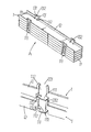
- FIG. 1 is a perspective view of a preferred embodiment of the present invention.
- FIG. 2 is a schematic view of an assembly of a fin of the preferred embodiment of the present invention.
- FIG. 3 is a view showing two fins to be engaged to each other in the preferred embodiment of the present invention.
- FIG. 4 is another view showing two fins to be engaged to each other in the preferred embodiment of the present invention.
- FIG. 5 is a schematic view showing that two fins are engaged to each other in the preferred embodiment of the present invention.
- a heat sink (A) is comprised of multiple fins ( 1 ) overlapped on one another.
- each of those fins ( 1 ) is provided with a base plate ( 11 )
- a sidewall ( 12 ) is each provided on both of the longer sides of the fin ( 1 )
- multiple locking members ( 13 ) are provided on both longer sides of the fin ( 1 ).
- Those multiple locking members ( 13 ) on one side are provided at where relatively to those on the other side of the base plate ( 11 ).
- each base plate ( 11 ) is directly punched in one-piece configuration.
- Each locking member ( 13 ) has two teeth ( 131 ) extending upward from the sidewall ( 12 ) and curved inwardly at the tip facing each other.
- each tooth ( 131 ) defines a primary locking edge ( 1311 ) provided with elongation and the curved part of each tooth ( 131 ), a secondary locking edge ( 1312 ).
- the primary and the secondary locking edges ( 1311 , 1312 ) define a locking gap ( 132 ); and both of secondary locking edges ( 1312 ), a window ( 133 ).
- a latch ( 111 ) is provided to the locking gap ( 132 ) at where in relation to its bottom.
- a recess ( 112 ) is each provided on both sides of the latch ( 111 ).
- the width of the latch ( 111 ) is slightly greater than the spacing between both of the primary locking edges ( 1311 ) and slightly smaller than that of the window ( 133 ).
- both fins ( 1 ) are overlapped to each other, both fins ( 1 ) are placed in a mold (C) in sequence, wherein; both sidewalls ( 12 ) together with all the locking members ( 13 ) of each fin ( 1 ) are folded up at right angel. Also referring to FIGS. 3, 4 , and 5 , the latch ( 111 ) of the upper fin ( 1 ) is locked in the locking gap ( 132 ) through the window ( 133 ) of the lower fin ( 1 ).
- a jig is used to slightly fold in both of the secondary locking edges ( 1312 ) towards the locking gap ( 132 ) for both of the secondary locking edges ( 1312 ) of both teeth ( 131 ) to hold the latch ( 111 ) in place. Meanwhile, the elongation from both of the primary locking edges ( 1311 ) of both teeth ( 131 ) to trap the latch ( 111 ) in the locking gap ( 132 ) to secure the latch ( 111 ) for both of the upper and the lower fins to be tightly incorporated to each other. More fins ( 1 ) are overlapped one another in the same locking manner to form the heat sink (A).
- each fin ( 1 ) in the heat sink (A) forms an area for heat dispersion and a specific spacing is defined between any two abutted latches ( 111 , 111 ′) to provide good heat dispersion gap (B) between any two abutted fins ( 1 ) in the heat sink (A) to measure sure that the base plate ( 11 ) of each fin ( 1 ) in the heat sink (A) is able to disperse the heat for the heat sink (A) to prevail its optimal heat dispersion effects, continuously and reliably.
- the configuration of the present invention differs from the prior art in that the latter has to rely upon insertion boards for all the fins to be inserted into those insertion boards with a pressboard to be placed upon the most top fin. Therefore, the present invention provides the advantages of easier assembly, lower production cost and increased production capacity.
- the present invention provides an improved structure for overlapping multiple fins in a hear sink in a firm and steady configuration, wherein any abutted fins to be tightly incorporated to each other by having a latch on a sidewall of the upper fin to be locked in a locking gap with the width of the latch slightly greater than the spacing between two primary locking edges of the locking gap. Therefore, this application for a utility patent is duly filed. However, it should be noted that the preferred embodiment given in the specification is in no way to limit the present invention, and any structure, installation or characteristics that is similar or equivalent to that of the present invention shall be included within the purposes and claims of the present invention.
Abstract
Description
Claims (3)
Priority Applications (1)
| Application Number | Priority Date | Filing Date | Title |
|---|---|---|---|
| US10/418,145 US6754079B1 (en) | 2003-04-18 | 2003-04-18 | KD heat sink fins |
Applications Claiming Priority (1)
| Application Number | Priority Date | Filing Date | Title |
|---|---|---|---|
| US10/418,145 US6754079B1 (en) | 2003-04-18 | 2003-04-18 | KD heat sink fins |
Publications (1)
| Publication Number | Publication Date |
|---|---|
| US6754079B1 true US6754079B1 (en) | 2004-06-22 |
Family
ID=32469203
Family Applications (1)
| Application Number | Title | Priority Date | Filing Date |
|---|---|---|---|
| US10/418,145 Expired - Fee Related US6754079B1 (en) | 2003-04-18 | 2003-04-18 | KD heat sink fins |
Country Status (1)
| Country | Link |
|---|---|
| US (1) | US6754079B1 (en) |
Cited By (17)
| Publication number | Priority date | Publication date | Assignee | Title |
|---|---|---|---|---|
| US20040104013A1 (en) * | 2002-08-14 | 2004-06-03 | Yuan-Chang Yeh | Engaging structure for heat sink |
| US20040112569A1 (en) * | 2002-11-14 | 2004-06-17 | Lin You-Tien | Heat sink element coupling structure (2) |
| US20040231827A1 (en) * | 2003-05-09 | 2004-11-25 | Fu Xue Ding | Heat dissipation device with interlocking fin plates |
| US20050022972A1 (en) * | 2003-07-15 | 2005-02-03 | Chen Cheng-Tung | Heat sink element coupling structure |
| US20050115702A1 (en) * | 2003-12-02 | 2005-06-02 | Kuo-Len Lin | Fin assembly of heat sink |
| US20060012961A1 (en) * | 2004-07-13 | 2006-01-19 | Foxconn Technology Co., Ltd. | Heat-dissipating fin assembly for heat sink |
| US20060032610A1 (en) * | 2004-08-10 | 2006-02-16 | Hon Hai Precision Industry Co., Ltd. | Cooling fin assembly |
| US20060118276A1 (en) * | 2004-12-03 | 2006-06-08 | Foxconn Tecnology Co., Ltd. | Heat sink |
| US20060162920A1 (en) * | 2005-01-24 | 2006-07-27 | Yuh-Cheng Chemical Ltd. | Heat sink |
| US20060285296A1 (en) * | 2005-06-21 | 2006-12-21 | Yuh-Cheng Chemical Ltd. | Heat sink and its fabrication method |
| US7165601B1 (en) * | 2003-12-12 | 2007-01-23 | Sony Corporation | Radiation fin, cooling device, electronic equipment, and manufacturing method of cooling device |
| US20070084583A1 (en) * | 2005-10-14 | 2007-04-19 | Wen-Hsing Pan | Structure for connecting radiating fins |
| US20070246190A1 (en) * | 2006-04-19 | 2007-10-25 | Wen-Chen Wei | Heat dissipating structure having different compactness |
| US20070256812A1 (en) * | 2006-04-19 | 2007-11-08 | Wen-Chen Wei | Multidirectional heat dissipating structure |
| GB2442029A (en) * | 2006-04-13 | 2008-03-26 | Kunshan Anli Precise Metal Co | Fin plate connection structure for a CPU heat sink |
| US20080101028A1 (en) * | 2006-10-31 | 2008-05-01 | Foxconn Technology Co., Ltd. | Heat sink |
| US10531596B1 (en) * | 2018-06-26 | 2020-01-07 | Cooler Master Co., Ltd. | Assemblable cooling fin assembly and assembly method thereof |
Citations (10)
| Publication number | Priority date | Publication date | Assignee | Title |
|---|---|---|---|---|
| US5558155A (en) * | 1993-08-06 | 1996-09-24 | Mitsubishi Denki Kabushiki Kaisha | Cooling apparatus and assembling method thereof |
| US6104609A (en) * | 1999-02-03 | 2000-08-15 | Chen; A-Chiang | Structure computer central processing unit heat dissipater |
| US6336498B1 (en) * | 2001-04-27 | 2002-01-08 | Wen-Chen Wei | Leaf piece structure for heat dissipater |
| US6340056B1 (en) * | 2001-04-24 | 2002-01-22 | Chaun-Choung Technology Corp. | Flow channel type heat dissipating fin set |
| US6386275B1 (en) * | 2001-08-16 | 2002-05-14 | Chaun-Choung Technology Corp. | Surrounding type fin-retaining structure of heat radiator |
| US6449160B1 (en) * | 2001-07-25 | 2002-09-10 | Tzu Mien Tsai | Radiation fin assembly for heat sink or the like |
| US6474407B1 (en) * | 2001-12-12 | 2002-11-05 | Delta Electronics Inc. | Composite heat sink with high density fins and assembling method for the same |
| US6607028B1 (en) * | 2002-07-29 | 2003-08-19 | Waffer Technology Corp. | Positioning structure for heat dissipating fins |
| US6607023B2 (en) * | 2001-12-20 | 2003-08-19 | Datech Technology Co., Ltd. | Structure for assembling a heat sink assembly |
| US6639802B1 (en) * | 2002-11-05 | 2003-10-28 | Hon Hai Precision Ind. Co., Ltd. | Heat sink with interlocked fins |
-
2003
- 2003-04-18 US US10/418,145 patent/US6754079B1/en not_active Expired - Fee Related
Patent Citations (10)
| Publication number | Priority date | Publication date | Assignee | Title |
|---|---|---|---|---|
| US5558155A (en) * | 1993-08-06 | 1996-09-24 | Mitsubishi Denki Kabushiki Kaisha | Cooling apparatus and assembling method thereof |
| US6104609A (en) * | 1999-02-03 | 2000-08-15 | Chen; A-Chiang | Structure computer central processing unit heat dissipater |
| US6340056B1 (en) * | 2001-04-24 | 2002-01-22 | Chaun-Choung Technology Corp. | Flow channel type heat dissipating fin set |
| US6336498B1 (en) * | 2001-04-27 | 2002-01-08 | Wen-Chen Wei | Leaf piece structure for heat dissipater |
| US6449160B1 (en) * | 2001-07-25 | 2002-09-10 | Tzu Mien Tsai | Radiation fin assembly for heat sink or the like |
| US6386275B1 (en) * | 2001-08-16 | 2002-05-14 | Chaun-Choung Technology Corp. | Surrounding type fin-retaining structure of heat radiator |
| US6474407B1 (en) * | 2001-12-12 | 2002-11-05 | Delta Electronics Inc. | Composite heat sink with high density fins and assembling method for the same |
| US6607023B2 (en) * | 2001-12-20 | 2003-08-19 | Datech Technology Co., Ltd. | Structure for assembling a heat sink assembly |
| US6607028B1 (en) * | 2002-07-29 | 2003-08-19 | Waffer Technology Corp. | Positioning structure for heat dissipating fins |
| US6639802B1 (en) * | 2002-11-05 | 2003-10-28 | Hon Hai Precision Ind. Co., Ltd. | Heat sink with interlocked fins |
Cited By (28)
| Publication number | Priority date | Publication date | Assignee | Title |
|---|---|---|---|---|
| US20040104013A1 (en) * | 2002-08-14 | 2004-06-03 | Yuan-Chang Yeh | Engaging structure for heat sink |
| US7025122B2 (en) * | 2002-11-14 | 2006-04-11 | Lin You-Tien | Heat sink element coupling structure (2) |
| US20040112569A1 (en) * | 2002-11-14 | 2004-06-17 | Lin You-Tien | Heat sink element coupling structure (2) |
| US20040231827A1 (en) * | 2003-05-09 | 2004-11-25 | Fu Xue Ding | Heat dissipation device with interlocking fin plates |
| US7028755B2 (en) * | 2003-05-09 | 2006-04-18 | Hon Hai Precision Ind. Co., Ltd. | Heat dissipation device with interlocking fin plates |
| US20050022972A1 (en) * | 2003-07-15 | 2005-02-03 | Chen Cheng-Tung | Heat sink element coupling structure |
| US6942026B2 (en) * | 2003-12-02 | 2005-09-13 | Golden Sun News Techniques Co., Ltd. | Fin assembly of heat sink |
| US20050115702A1 (en) * | 2003-12-02 | 2005-06-02 | Kuo-Len Lin | Fin assembly of heat sink |
| US7377306B2 (en) * | 2003-12-12 | 2008-05-27 | Sony Corporation | Radiation fin, cooling device, electronic equipment, and manufacturing method of cooling device |
| US20070084584A1 (en) * | 2003-12-12 | 2007-04-19 | Sony Corporation | Radiation fin, cooling device, electronic equipment, and manufacturing method of cooling device |
| US7165601B1 (en) * | 2003-12-12 | 2007-01-23 | Sony Corporation | Radiation fin, cooling device, electronic equipment, and manufacturing method of cooling device |
| US20060012961A1 (en) * | 2004-07-13 | 2006-01-19 | Foxconn Technology Co., Ltd. | Heat-dissipating fin assembly for heat sink |
| US7190588B2 (en) * | 2004-07-13 | 2007-03-13 | Fu Zhun Precision Industry (Shen Zhen) Co., Ltd. | Heat-dissipating fin assembly for heat sink |
| US7163049B2 (en) * | 2004-08-10 | 2007-01-16 | Fu Zhun Precision Industry (Shenzhen) Co., Ltd. | Cooling fin assembly |
| US20060032610A1 (en) * | 2004-08-10 | 2006-02-16 | Hon Hai Precision Industry Co., Ltd. | Cooling fin assembly |
| US7121326B2 (en) * | 2004-12-03 | 2006-10-17 | Foxconn Technology Co., Ltd. | Heat sink |
| US20060118276A1 (en) * | 2004-12-03 | 2006-06-08 | Foxconn Tecnology Co., Ltd. | Heat sink |
| US20060162920A1 (en) * | 2005-01-24 | 2006-07-27 | Yuh-Cheng Chemical Ltd. | Heat sink |
| US20060285296A1 (en) * | 2005-06-21 | 2006-12-21 | Yuh-Cheng Chemical Ltd. | Heat sink and its fabrication method |
| US7304851B2 (en) * | 2005-06-21 | 2007-12-04 | Yuh-Cheng Chemical Ltd. | Heat sink and its fabrication method |
| US20070084583A1 (en) * | 2005-10-14 | 2007-04-19 | Wen-Hsing Pan | Structure for connecting radiating fins |
| GB2442029A (en) * | 2006-04-13 | 2008-03-26 | Kunshan Anli Precise Metal Co | Fin plate connection structure for a CPU heat sink |
| US20070256812A1 (en) * | 2006-04-19 | 2007-11-08 | Wen-Chen Wei | Multidirectional heat dissipating structure |
| US7370692B2 (en) * | 2006-04-19 | 2008-05-13 | Wen-Chen Wei | Heat dissipating structure having different compactness |
| US20070246190A1 (en) * | 2006-04-19 | 2007-10-25 | Wen-Chen Wei | Heat dissipating structure having different compactness |
| US20080101028A1 (en) * | 2006-10-31 | 2008-05-01 | Foxconn Technology Co., Ltd. | Heat sink |
| US7721790B2 (en) * | 2006-10-31 | 2010-05-25 | Foxconn Technology Co., Ltd. | Heat sink |
| US10531596B1 (en) * | 2018-06-26 | 2020-01-07 | Cooler Master Co., Ltd. | Assemblable cooling fin assembly and assembly method thereof |
Similar Documents
| Publication | Publication Date | Title |
|---|---|---|
| US6754079B1 (en) | KD heat sink fins | |
| US6449160B1 (en) | Radiation fin assembly for heat sink or the like | |
| US7441592B2 (en) | Cooler module | |
| US6883591B2 (en) | Stackable heat sink | |
| US20060203454A1 (en) | Heat sink for memory strips | |
| KR200472451Y1 (en) | Heat sink module | |
| US7028755B2 (en) | Heat dissipation device with interlocking fin plates | |
| US7190588B2 (en) | Heat-dissipating fin assembly for heat sink | |
| US20210105915A1 (en) | Electrical connector | |
| US20090183863A1 (en) | Connecting Structure for Connecting Heat Radiation Fins | |
| US20060162920A1 (en) | Heat sink | |
| US20040194922A1 (en) | Heat dissipation device with interlocking fins | |
| US6765799B1 (en) | Heat dissipating fins interlocking mechanism | |
| US6199627B1 (en) | Heat sink | |
| US6995981B2 (en) | Heat sink assembly with combined parallel fins | |
| US20030209342A1 (en) | Cooler assembly | |
| US7044197B2 (en) | Heat sink with combined fins | |
| US6942026B2 (en) | Fin assembly of heat sink | |
| US6644397B1 (en) | Combination sink | |
| US20040112569A1 (en) | Heat sink element coupling structure (2) | |
| US20070084583A1 (en) | Structure for connecting radiating fins | |
| US10531596B1 (en) | Assemblable cooling fin assembly and assembly method thereof | |
| US7694720B2 (en) | Sectional modular heat sink | |
| KR101793952B1 (en) | Solar wafer carrier | |
| KR200191128Y1 (en) | Heat sink |
Legal Events
| Date | Code | Title | Description |
|---|---|---|---|
| AS | Assignment |
Owner name: KU, HSIU-LI, TAIWAN Free format text: ASSIGNMENT OF ASSIGNORS INTEREST;ASSIGNOR:CHANG, HUNG-CHUN;REEL/FRAME:017498/0448 Effective date: 20060103 |
|
| AS | Assignment |
Owner name: SCENICONN ELECTRONIC CO., LTD., TAIWAN Free format text: ASSIGNMENT OF ASSIGNORS INTEREST;ASSIGNOR:KU, HSIU-LI;REEL/FRAME:017712/0912 Effective date: 20060118 |
|
| REMI | Maintenance fee reminder mailed | ||
| LAPS | Lapse for failure to pay maintenance fees | ||
| STCH | Information on status: patent discontinuation |
Free format text: PATENT EXPIRED DUE TO NONPAYMENT OF MAINTENANCE FEES UNDER 37 CFR 1.362 |
|
| FP | Lapsed due to failure to pay maintenance fee |
Effective date: 20080622 |