US6698423B1 - Methods and apparatus to generate liquid ambulatory oxygen from an oxygen concentrator - Google Patents
Methods and apparatus to generate liquid ambulatory oxygen from an oxygen concentrator Download PDFInfo
- Publication number
- US6698423B1 US6698423B1 US09/420,892 US42089299A US6698423B1 US 6698423 B1 US6698423 B1 US 6698423B1 US 42089299 A US42089299 A US 42089299A US 6698423 B1 US6698423 B1 US 6698423B1
- Authority
- US
- United States
- Prior art keywords
- oxygen
- dewar
- liquid
- condenser
- concentrator
- Prior art date
- Legal status (The legal status is an assumption and is not a legal conclusion. Google has not performed a legal analysis and makes no representation as to the accuracy of the status listed.)
- Ceased
Links
- 239000001301 oxygen Substances 0.000 title claims abstract description 198
- 229910052760 oxygen Inorganic materials 0.000 title claims abstract description 198
- QVGXLLKOCUKJST-UHFFFAOYSA-N atomic oxygen Chemical compound [O] QVGXLLKOCUKJST-UHFFFAOYSA-N 0.000 title claims abstract 40
- 239000007788 liquid Substances 0.000 title claims description 116
- 238000000034 method Methods 0.000 title claims description 23
- MYMOFIZGZYHOMD-UHFFFAOYSA-N Dioxygen Chemical compound O=O MYMOFIZGZYHOMD-UHFFFAOYSA-N 0.000 claims abstract description 271
- 238000003860 storage Methods 0.000 claims abstract description 42
- 239000007789 gas Substances 0.000 claims abstract description 41
- 238000004891 communication Methods 0.000 claims abstract description 17
- 229910001882 dioxygen Inorganic materials 0.000 claims abstract description 10
- 239000012530 fluid Substances 0.000 claims abstract description 7
- 239000012080 ambient air Substances 0.000 claims abstract description 4
- 238000009833 condensation Methods 0.000 claims description 20
- 230000005494 condensation Effects 0.000 claims description 20
- 230000001965 increasing effect Effects 0.000 claims description 20
- 238000001816 cooling Methods 0.000 claims description 17
- 230000007246 mechanism Effects 0.000 claims description 17
- 230000005484 gravity Effects 0.000 claims description 13
- 239000012535 impurity Substances 0.000 claims description 13
- 238000013022 venting Methods 0.000 claims description 12
- 239000003570 air Substances 0.000 claims description 11
- 238000010438 heat treatment Methods 0.000 claims description 10
- 229930195733 hydrocarbon Natural products 0.000 claims description 10
- 150000002430 hydrocarbons Chemical class 0.000 claims description 10
- 239000006200 vaporizer Substances 0.000 claims description 7
- 238000010926 purge Methods 0.000 claims description 5
- 239000007787 solid Substances 0.000 claims description 5
- 239000000356 contaminant Substances 0.000 claims description 4
- 230000002708 enhancing effect Effects 0.000 claims description 4
- 238000007710 freezing Methods 0.000 claims description 2
- 230000008014 freezing Effects 0.000 claims description 2
- 238000005516 engineering process Methods 0.000 abstract description 2
- IJGRMHOSHXDMSA-UHFFFAOYSA-N Atomic nitrogen Chemical compound N#N IJGRMHOSHXDMSA-UHFFFAOYSA-N 0.000 description 42
- XKRFYHLGVUSROY-UHFFFAOYSA-N Argon Chemical compound [Ar] XKRFYHLGVUSROY-UHFFFAOYSA-N 0.000 description 26
- 238000012546 transfer Methods 0.000 description 25
- 239000000203 mixture Substances 0.000 description 23
- 229910052757 nitrogen Inorganic materials 0.000 description 21
- XLYOFNOQVPJJNP-UHFFFAOYSA-N water Chemical compound O XLYOFNOQVPJJNP-UHFFFAOYSA-N 0.000 description 16
- 229910052786 argon Inorganic materials 0.000 description 13
- CURLTUGMZLYLDI-UHFFFAOYSA-N Carbon dioxide Chemical compound O=C=O CURLTUGMZLYLDI-UHFFFAOYSA-N 0.000 description 9
- 230000000153 supplemental effect Effects 0.000 description 9
- 238000009835 boiling Methods 0.000 description 8
- 238000010586 diagram Methods 0.000 description 8
- 239000003507 refrigerant Substances 0.000 description 7
- RYGMFSIKBFXOCR-UHFFFAOYSA-N Copper Chemical compound [Cu] RYGMFSIKBFXOCR-UHFFFAOYSA-N 0.000 description 6
- 229910052802 copper Inorganic materials 0.000 description 6
- 239000010949 copper Substances 0.000 description 6
- 238000009825 accumulation Methods 0.000 description 5
- 229910002092 carbon dioxide Inorganic materials 0.000 description 5
- 230000006835 compression Effects 0.000 description 5
- 238000007906 compression Methods 0.000 description 5
- 238000002640 oxygen therapy Methods 0.000 description 4
- 230000008569 process Effects 0.000 description 4
- 238000001179 sorption measurement Methods 0.000 description 4
- 239000001569 carbon dioxide Substances 0.000 description 3
- 230000006870 function Effects 0.000 description 3
- 239000000463 material Substances 0.000 description 3
- 238000012544 monitoring process Methods 0.000 description 3
- 230000001105 regulatory effect Effects 0.000 description 3
- 230000008439 repair process Effects 0.000 description 3
- 208000006545 Chronic Obstructive Pulmonary Disease Diseases 0.000 description 2
- 206010021143 Hypoxia Diseases 0.000 description 2
- 208000019693 Lung disease Diseases 0.000 description 2
- VVTSZOCINPYFDP-UHFFFAOYSA-N [O].[Ar] Chemical compound [O].[Ar] VVTSZOCINPYFDP-UHFFFAOYSA-N 0.000 description 2
- 238000013459 approach Methods 0.000 description 2
- 230000008901 benefit Effects 0.000 description 2
- 230000015556 catabolic process Effects 0.000 description 2
- 238000006731 degradation reaction Methods 0.000 description 2
- 238000001704 evaporation Methods 0.000 description 2
- 230000008020 evaporation Effects 0.000 description 2
- 230000036541 health Effects 0.000 description 2
- 238000012423 maintenance Methods 0.000 description 2
- 239000002808 molecular sieve Substances 0.000 description 2
- 238000006213 oxygenation reaction Methods 0.000 description 2
- 230000000737 periodic effect Effects 0.000 description 2
- 239000012071 phase Substances 0.000 description 2
- URGAHOPLAPQHLN-UHFFFAOYSA-N sodium aluminosilicate Chemical compound [Na+].[Al+3].[O-][Si]([O-])=O.[O-][Si]([O-])=O URGAHOPLAPQHLN-UHFFFAOYSA-N 0.000 description 2
- 238000012360 testing method Methods 0.000 description 2
- 230000000007 visual effect Effects 0.000 description 2
- 208000030507 AIDS Diseases 0.000 description 1
- 206010014561 Emphysema Diseases 0.000 description 1
- UFHFLCQGNIYNRP-UHFFFAOYSA-N Hydrogen Chemical compound [H][H] UFHFLCQGNIYNRP-UHFFFAOYSA-N 0.000 description 1
- OLBVUFHMDRJKTK-UHFFFAOYSA-N [N].[O] Chemical compound [N].[O] OLBVUFHMDRJKTK-UHFFFAOYSA-N 0.000 description 1
- 230000003213 activating effect Effects 0.000 description 1
- 208000006673 asthma Diseases 0.000 description 1
- 235000013405 beer Nutrition 0.000 description 1
- 230000009286 beneficial effect Effects 0.000 description 1
- 239000008280 blood Substances 0.000 description 1
- 210000004369 blood Anatomy 0.000 description 1
- 210000004556 brain Anatomy 0.000 description 1
- 230000008859 change Effects 0.000 description 1
- 238000002485 combustion reaction Methods 0.000 description 1
- 239000012141 concentrate Substances 0.000 description 1
- 230000001276 controlling effect Effects 0.000 description 1
- 239000002826 coolant Substances 0.000 description 1
- 238000013461 design Methods 0.000 description 1
- 238000011161 development Methods 0.000 description 1
- 230000003467 diminishing effect Effects 0.000 description 1
- 230000000694 effects Effects 0.000 description 1
- 239000000284 extract Substances 0.000 description 1
- 210000002216 heart Anatomy 0.000 description 1
- 208000019622 heart disease Diseases 0.000 description 1
- 239000001307 helium Substances 0.000 description 1
- 229910052734 helium Inorganic materials 0.000 description 1
- SWQJXJOGLNCZEY-UHFFFAOYSA-N helium atom Chemical group [He] SWQJXJOGLNCZEY-UHFFFAOYSA-N 0.000 description 1
- 239000001257 hydrogen Substances 0.000 description 1
- 229910052739 hydrogen Inorganic materials 0.000 description 1
- 208000018875 hypoxemia Diseases 0.000 description 1
- 230000010354 integration Effects 0.000 description 1
- 210000003734 kidney Anatomy 0.000 description 1
- 239000007791 liquid phase Substances 0.000 description 1
- 230000007774 longterm Effects 0.000 description 1
- 230000007257 malfunction Effects 0.000 description 1
- 238000010327 methods by industry Methods 0.000 description 1
- 239000008267 milk Substances 0.000 description 1
- 210000004080 milk Anatomy 0.000 description 1
- 235000013336 milk Nutrition 0.000 description 1
- 238000012986 modification Methods 0.000 description 1
- 230000004048 modification Effects 0.000 description 1
- DOTMOQHOJINYBL-UHFFFAOYSA-N molecular nitrogen;molecular oxygen Chemical compound N#N.O=O DOTMOQHOJINYBL-UHFFFAOYSA-N 0.000 description 1
- 229910052754 neon Inorganic materials 0.000 description 1
- GKAOGPIIYCISHV-UHFFFAOYSA-N neon atom Chemical compound [Ne] GKAOGPIIYCISHV-UHFFFAOYSA-N 0.000 description 1
- 208000014055 occupational lung disease Diseases 0.000 description 1
- 210000000056 organ Anatomy 0.000 description 1
- 238000009428 plumbing Methods 0.000 description 1
- 208000005069 pulmonary fibrosis Diseases 0.000 description 1
- 201000003651 pulmonary sarcoidosis Diseases 0.000 description 1
- 230000000241 respiratory effect Effects 0.000 description 1
- 210000002345 respiratory system Anatomy 0.000 description 1
- 238000004513 sizing Methods 0.000 description 1
- 230000005236 sound signal Effects 0.000 description 1
- 238000002560 therapeutic procedure Methods 0.000 description 1
- 239000002912 waste gas Substances 0.000 description 1
- 239000002699 waste material Substances 0.000 description 1
- 230000003442 weekly effect Effects 0.000 description 1
Images


Classifications
-
- B—PERFORMING OPERATIONS; TRANSPORTING
- B01—PHYSICAL OR CHEMICAL PROCESSES OR APPARATUS IN GENERAL
- B01D—SEPARATION
- B01D53/00—Separation of gases or vapours; Recovering vapours of volatile solvents from gases; Chemical or biological purification of waste gases, e.g. engine exhaust gases, smoke, fumes, flue gases, aerosols
- B01D53/02—Separation of gases or vapours; Recovering vapours of volatile solvents from gases; Chemical or biological purification of waste gases, e.g. engine exhaust gases, smoke, fumes, flue gases, aerosols by adsorption, e.g. preparative gas chromatography
- B01D53/04—Separation of gases or vapours; Recovering vapours of volatile solvents from gases; Chemical or biological purification of waste gases, e.g. engine exhaust gases, smoke, fumes, flue gases, aerosols by adsorption, e.g. preparative gas chromatography with stationary adsorbents
- B01D53/0454—Controlling adsorption
-
- B—PERFORMING OPERATIONS; TRANSPORTING
- B01—PHYSICAL OR CHEMICAL PROCESSES OR APPARATUS IN GENERAL
- B01D—SEPARATION
- B01D5/00—Condensation of vapours; Recovering volatile solvents by condensation
- B01D5/0033—Other features
- B01D5/0039—Recuperation of heat, e.g. use of heat pump(s), compression
-
- B—PERFORMING OPERATIONS; TRANSPORTING
- B01—PHYSICAL OR CHEMICAL PROCESSES OR APPARATUS IN GENERAL
- B01D—SEPARATION
- B01D53/00—Separation of gases or vapours; Recovering vapours of volatile solvents from gases; Chemical or biological purification of waste gases, e.g. engine exhaust gases, smoke, fumes, flue gases, aerosols
- B01D53/02—Separation of gases or vapours; Recovering vapours of volatile solvents from gases; Chemical or biological purification of waste gases, e.g. engine exhaust gases, smoke, fumes, flue gases, aerosols by adsorption, e.g. preparative gas chromatography
- B01D53/04—Separation of gases or vapours; Recovering vapours of volatile solvents from gases; Chemical or biological purification of waste gases, e.g. engine exhaust gases, smoke, fumes, flue gases, aerosols by adsorption, e.g. preparative gas chromatography with stationary adsorbents
- B01D53/047—Pressure swing adsorption
-
- F—MECHANICAL ENGINEERING; LIGHTING; HEATING; WEAPONS; BLASTING
- F17—STORING OR DISTRIBUTING GASES OR LIQUIDS
- F17C—VESSELS FOR CONTAINING OR STORING COMPRESSED, LIQUEFIED OR SOLIDIFIED GASES; FIXED-CAPACITY GAS-HOLDERS; FILLING VESSELS WITH, OR DISCHARGING FROM VESSELS, COMPRESSED, LIQUEFIED, OR SOLIDIFIED GASES
- F17C6/00—Methods and apparatus for filling vessels not under pressure with liquefied or solidified gases
-
- F—MECHANICAL ENGINEERING; LIGHTING; HEATING; WEAPONS; BLASTING
- F25—REFRIGERATION OR COOLING; COMBINED HEATING AND REFRIGERATION SYSTEMS; HEAT PUMP SYSTEMS; MANUFACTURE OR STORAGE OF ICE; LIQUEFACTION SOLIDIFICATION OF GASES
- F25J—LIQUEFACTION, SOLIDIFICATION OR SEPARATION OF GASES OR GASEOUS OR LIQUEFIED GASEOUS MIXTURES BY PRESSURE AND COLD TREATMENT OR BY BRINGING THEM INTO THE SUPERCRITICAL STATE
- F25J1/00—Processes or apparatus for liquefying or solidifying gases or gaseous mixtures
- F25J1/0002—Processes or apparatus for liquefying or solidifying gases or gaseous mixtures characterised by the fluid to be liquefied
- F25J1/0012—Primary atmospheric gases, e.g. air
- F25J1/0017—Oxygen
-
- F—MECHANICAL ENGINEERING; LIGHTING; HEATING; WEAPONS; BLASTING
- F25—REFRIGERATION OR COOLING; COMBINED HEATING AND REFRIGERATION SYSTEMS; HEAT PUMP SYSTEMS; MANUFACTURE OR STORAGE OF ICE; LIQUEFACTION SOLIDIFICATION OF GASES
- F25J—LIQUEFACTION, SOLIDIFICATION OR SEPARATION OF GASES OR GASEOUS OR LIQUEFIED GASEOUS MIXTURES BY PRESSURE AND COLD TREATMENT OR BY BRINGING THEM INTO THE SUPERCRITICAL STATE
- F25J1/00—Processes or apparatus for liquefying or solidifying gases or gaseous mixtures
- F25J1/003—Processes or apparatus for liquefying or solidifying gases or gaseous mixtures characterised by the kind of cold generation within the liquefaction unit for compensating heat leaks and liquid production
- F25J1/0047—Processes or apparatus for liquefying or solidifying gases or gaseous mixtures characterised by the kind of cold generation within the liquefaction unit for compensating heat leaks and liquid production using an "external" refrigerant stream in a closed vapor compression cycle
- F25J1/0052—Processes or apparatus for liquefying or solidifying gases or gaseous mixtures characterised by the kind of cold generation within the liquefaction unit for compensating heat leaks and liquid production using an "external" refrigerant stream in a closed vapor compression cycle by vaporising a liquid refrigerant stream
-
- F—MECHANICAL ENGINEERING; LIGHTING; HEATING; WEAPONS; BLASTING
- F25—REFRIGERATION OR COOLING; COMBINED HEATING AND REFRIGERATION SYSTEMS; HEAT PUMP SYSTEMS; MANUFACTURE OR STORAGE OF ICE; LIQUEFACTION SOLIDIFICATION OF GASES
- F25J—LIQUEFACTION, SOLIDIFICATION OR SEPARATION OF GASES OR GASEOUS OR LIQUEFIED GASEOUS MIXTURES BY PRESSURE AND COLD TREATMENT OR BY BRINGING THEM INTO THE SUPERCRITICAL STATE
- F25J1/00—Processes or apparatus for liquefying or solidifying gases or gaseous mixtures
- F25J1/02—Processes or apparatus for liquefying or solidifying gases or gaseous mixtures requiring the use of refrigeration, e.g. of helium or hydrogen ; Details and kind of the refrigeration system used; Integration with other units or processes; Controlling aspects of the process
- F25J1/0211—Processes or apparatus for liquefying or solidifying gases or gaseous mixtures requiring the use of refrigeration, e.g. of helium or hydrogen ; Details and kind of the refrigeration system used; Integration with other units or processes; Controlling aspects of the process using a multi-component refrigerant [MCR] fluid in a closed vapor compression cycle
- F25J1/0212—Processes or apparatus for liquefying or solidifying gases or gaseous mixtures requiring the use of refrigeration, e.g. of helium or hydrogen ; Details and kind of the refrigeration system used; Integration with other units or processes; Controlling aspects of the process using a multi-component refrigerant [MCR] fluid in a closed vapor compression cycle as a single flow MCR cycle
-
- F—MECHANICAL ENGINEERING; LIGHTING; HEATING; WEAPONS; BLASTING
- F25—REFRIGERATION OR COOLING; COMBINED HEATING AND REFRIGERATION SYSTEMS; HEAT PUMP SYSTEMS; MANUFACTURE OR STORAGE OF ICE; LIQUEFACTION SOLIDIFICATION OF GASES
- F25J—LIQUEFACTION, SOLIDIFICATION OR SEPARATION OF GASES OR GASEOUS OR LIQUEFIED GASEOUS MIXTURES BY PRESSURE AND COLD TREATMENT OR BY BRINGING THEM INTO THE SUPERCRITICAL STATE
- F25J1/00—Processes or apparatus for liquefying or solidifying gases or gaseous mixtures
- F25J1/02—Processes or apparatus for liquefying or solidifying gases or gaseous mixtures requiring the use of refrigeration, e.g. of helium or hydrogen ; Details and kind of the refrigeration system used; Integration with other units or processes; Controlling aspects of the process
- F25J1/0225—Processes or apparatus for liquefying or solidifying gases or gaseous mixtures requiring the use of refrigeration, e.g. of helium or hydrogen ; Details and kind of the refrigeration system used; Integration with other units or processes; Controlling aspects of the process using other external refrigeration means not provided before, e.g. heat driven absorption chillers
-
- F—MECHANICAL ENGINEERING; LIGHTING; HEATING; WEAPONS; BLASTING
- F25—REFRIGERATION OR COOLING; COMBINED HEATING AND REFRIGERATION SYSTEMS; HEAT PUMP SYSTEMS; MANUFACTURE OR STORAGE OF ICE; LIQUEFACTION SOLIDIFICATION OF GASES
- F25J—LIQUEFACTION, SOLIDIFICATION OR SEPARATION OF GASES OR GASEOUS OR LIQUEFIED GASEOUS MIXTURES BY PRESSURE AND COLD TREATMENT OR BY BRINGING THEM INTO THE SUPERCRITICAL STATE
- F25J1/00—Processes or apparatus for liquefying or solidifying gases or gaseous mixtures
- F25J1/02—Processes or apparatus for liquefying or solidifying gases or gaseous mixtures requiring the use of refrigeration, e.g. of helium or hydrogen ; Details and kind of the refrigeration system used; Integration with other units or processes; Controlling aspects of the process
- F25J1/0243—Start-up or control of the process; Details of the apparatus used; Details of the refrigerant compression system used
- F25J1/0244—Operation; Control and regulation; Instrumentation
-
- F—MECHANICAL ENGINEERING; LIGHTING; HEATING; WEAPONS; BLASTING
- F25—REFRIGERATION OR COOLING; COMBINED HEATING AND REFRIGERATION SYSTEMS; HEAT PUMP SYSTEMS; MANUFACTURE OR STORAGE OF ICE; LIQUEFACTION SOLIDIFICATION OF GASES
- F25J—LIQUEFACTION, SOLIDIFICATION OR SEPARATION OF GASES OR GASEOUS OR LIQUEFIED GASEOUS MIXTURES BY PRESSURE AND COLD TREATMENT OR BY BRINGING THEM INTO THE SUPERCRITICAL STATE
- F25J1/00—Processes or apparatus for liquefying or solidifying gases or gaseous mixtures
- F25J1/02—Processes or apparatus for liquefying or solidifying gases or gaseous mixtures requiring the use of refrigeration, e.g. of helium or hydrogen ; Details and kind of the refrigeration system used; Integration with other units or processes; Controlling aspects of the process
- F25J1/0243—Start-up or control of the process; Details of the apparatus used; Details of the refrigerant compression system used
- F25J1/0257—Construction and layout of liquefaction equipments, e.g. valves, machines
- F25J1/0275—Construction and layout of liquefaction equipments, e.g. valves, machines adapted for special use of the liquefaction unit, e.g. portable or transportable devices
- F25J1/0276—Laboratory or other miniature devices
-
- A—HUMAN NECESSITIES
- A61—MEDICAL OR VETERINARY SCIENCE; HYGIENE
- A61M—DEVICES FOR INTRODUCING MEDIA INTO, OR ONTO, THE BODY; DEVICES FOR TRANSDUCING BODY MEDIA OR FOR TAKING MEDIA FROM THE BODY; DEVICES FOR PRODUCING OR ENDING SLEEP OR STUPOR
- A61M2202/00—Special media to be introduced, removed or treated
- A61M2202/02—Gases
- A61M2202/0208—Oxygen
-
- A—HUMAN NECESSITIES
- A61—MEDICAL OR VETERINARY SCIENCE; HYGIENE
- A61M—DEVICES FOR INTRODUCING MEDIA INTO, OR ONTO, THE BODY; DEVICES FOR TRANSDUCING BODY MEDIA OR FOR TAKING MEDIA FROM THE BODY; DEVICES FOR PRODUCING OR ENDING SLEEP OR STUPOR
- A61M2202/00—Special media to be introduced, removed or treated
- A61M2202/03—Gases in liquid phase, e.g. cryogenic liquids
-
- B—PERFORMING OPERATIONS; TRANSPORTING
- B01—PHYSICAL OR CHEMICAL PROCESSES OR APPARATUS IN GENERAL
- B01D—SEPARATION
- B01D2253/00—Adsorbents used in seperation treatment of gases and vapours
- B01D2253/10—Inorganic adsorbents
- B01D2253/106—Silica or silicates
- B01D2253/108—Zeolites
-
- B—PERFORMING OPERATIONS; TRANSPORTING
- B01—PHYSICAL OR CHEMICAL PROCESSES OR APPARATUS IN GENERAL
- B01D—SEPARATION
- B01D2253/00—Adsorbents used in seperation treatment of gases and vapours
- B01D2253/10—Inorganic adsorbents
- B01D2253/116—Molecular sieves other than zeolites
-
- B—PERFORMING OPERATIONS; TRANSPORTING
- B01—PHYSICAL OR CHEMICAL PROCESSES OR APPARATUS IN GENERAL
- B01D—SEPARATION
- B01D2256/00—Main component in the product gas stream after treatment
- B01D2256/12—Oxygen
-
- B—PERFORMING OPERATIONS; TRANSPORTING
- B01—PHYSICAL OR CHEMICAL PROCESSES OR APPARATUS IN GENERAL
- B01D—SEPARATION
- B01D2257/00—Components to be removed
- B01D2257/10—Single element gases other than halogens
- B01D2257/102—Nitrogen
-
- B—PERFORMING OPERATIONS; TRANSPORTING
- B01—PHYSICAL OR CHEMICAL PROCESSES OR APPARATUS IN GENERAL
- B01D—SEPARATION
- B01D2257/00—Components to be removed
- B01D2257/40—Nitrogen compounds
- B01D2257/404—Nitrogen oxides other than dinitrogen oxide
-
- B—PERFORMING OPERATIONS; TRANSPORTING
- B01—PHYSICAL OR CHEMICAL PROCESSES OR APPARATUS IN GENERAL
- B01D—SEPARATION
- B01D2257/00—Components to be removed
- B01D2257/50—Carbon oxides
- B01D2257/502—Carbon monoxide
-
- B—PERFORMING OPERATIONS; TRANSPORTING
- B01—PHYSICAL OR CHEMICAL PROCESSES OR APPARATUS IN GENERAL
- B01D—SEPARATION
- B01D2257/00—Components to be removed
- B01D2257/50—Carbon oxides
- B01D2257/504—Carbon dioxide
-
- B—PERFORMING OPERATIONS; TRANSPORTING
- B01—PHYSICAL OR CHEMICAL PROCESSES OR APPARATUS IN GENERAL
- B01D—SEPARATION
- B01D2257/00—Components to be removed
- B01D2257/80—Water
-
- B—PERFORMING OPERATIONS; TRANSPORTING
- B01—PHYSICAL OR CHEMICAL PROCESSES OR APPARATUS IN GENERAL
- B01D—SEPARATION
- B01D2259/00—Type of treatment
- B01D2259/40—Further details for adsorption processes and devices
- B01D2259/40001—Methods relating to additional, e.g. intermediate, treatment of process gas
-
- B—PERFORMING OPERATIONS; TRANSPORTING
- B01—PHYSICAL OR CHEMICAL PROCESSES OR APPARATUS IN GENERAL
- B01D—SEPARATION
- B01D2259/00—Type of treatment
- B01D2259/40—Further details for adsorption processes and devices
- B01D2259/40007—Controlling pressure or temperature swing adsorption
- B01D2259/40009—Controlling pressure or temperature swing adsorption using sensors or gas analysers
-
- B—PERFORMING OPERATIONS; TRANSPORTING
- B01—PHYSICAL OR CHEMICAL PROCESSES OR APPARATUS IN GENERAL
- B01D—SEPARATION
- B01D2259/00—Type of treatment
- B01D2259/40—Further details for adsorption processes and devices
- B01D2259/416—Further details for adsorption processes and devices involving cryogenic temperature treatment
-
- B—PERFORMING OPERATIONS; TRANSPORTING
- B01—PHYSICAL OR CHEMICAL PROCESSES OR APPARATUS IN GENERAL
- B01D—SEPARATION
- B01D2259/00—Type of treatment
- B01D2259/45—Gas separation or purification devices adapted for specific applications
- B01D2259/4525—Gas separation or purification devices adapted for specific applications for storage and dispensing systems
-
- B—PERFORMING OPERATIONS; TRANSPORTING
- B01—PHYSICAL OR CHEMICAL PROCESSES OR APPARATUS IN GENERAL
- B01D—SEPARATION
- B01D2259/00—Type of treatment
- B01D2259/45—Gas separation or purification devices adapted for specific applications
- B01D2259/4533—Gas separation or purification devices adapted for specific applications for medical purposes
-
- B—PERFORMING OPERATIONS; TRANSPORTING
- B01—PHYSICAL OR CHEMICAL PROCESSES OR APPARATUS IN GENERAL
- B01D—SEPARATION
- B01D2259/00—Type of treatment
- B01D2259/45—Gas separation or purification devices adapted for specific applications
- B01D2259/4541—Gas separation or purification devices adapted for specific applications for portable use, e.g. gas masks
-
- B—PERFORMING OPERATIONS; TRANSPORTING
- B01—PHYSICAL OR CHEMICAL PROCESSES OR APPARATUS IN GENERAL
- B01D—SEPARATION
- B01D2259/00—Type of treatment
- B01D2259/45—Gas separation or purification devices adapted for specific applications
- B01D2259/455—Gas separation or purification devices adapted for specific applications for transportable use
-
- B—PERFORMING OPERATIONS; TRANSPORTING
- B01—PHYSICAL OR CHEMICAL PROCESSES OR APPARATUS IN GENERAL
- B01D—SEPARATION
- B01D53/00—Separation of gases or vapours; Recovering vapours of volatile solvents from gases; Chemical or biological purification of waste gases, e.g. engine exhaust gases, smoke, fumes, flue gases, aerosols
- B01D53/02—Separation of gases or vapours; Recovering vapours of volatile solvents from gases; Chemical or biological purification of waste gases, e.g. engine exhaust gases, smoke, fumes, flue gases, aerosols by adsorption, e.g. preparative gas chromatography
- B01D53/04—Separation of gases or vapours; Recovering vapours of volatile solvents from gases; Chemical or biological purification of waste gases, e.g. engine exhaust gases, smoke, fumes, flue gases, aerosols by adsorption, e.g. preparative gas chromatography with stationary adsorbents
- B01D53/047—Pressure swing adsorption
- B01D53/053—Pressure swing adsorption with storage or buffer vessel
-
- B—PERFORMING OPERATIONS; TRANSPORTING
- B01—PHYSICAL OR CHEMICAL PROCESSES OR APPARATUS IN GENERAL
- B01D—SEPARATION
- B01D53/00—Separation of gases or vapours; Recovering vapours of volatile solvents from gases; Chemical or biological purification of waste gases, e.g. engine exhaust gases, smoke, fumes, flue gases, aerosols
- B01D53/26—Drying gases or vapours
- B01D53/261—Drying gases or vapours by adsorption
-
- F—MECHANICAL ENGINEERING; LIGHTING; HEATING; WEAPONS; BLASTING
- F17—STORING OR DISTRIBUTING GASES OR LIQUIDS
- F17C—VESSELS FOR CONTAINING OR STORING COMPRESSED, LIQUEFIED OR SOLIDIFIED GASES; FIXED-CAPACITY GAS-HOLDERS; FILLING VESSELS WITH, OR DISCHARGING FROM VESSELS, COMPRESSED, LIQUEFIED, OR SOLIDIFIED GASES
- F17C2201/00—Vessel construction, in particular geometry, arrangement or size
- F17C2201/05—Size
- F17C2201/058—Size portable (<30 l)
-
- F—MECHANICAL ENGINEERING; LIGHTING; HEATING; WEAPONS; BLASTING
- F17—STORING OR DISTRIBUTING GASES OR LIQUIDS
- F17C—VESSELS FOR CONTAINING OR STORING COMPRESSED, LIQUEFIED OR SOLIDIFIED GASES; FIXED-CAPACITY GAS-HOLDERS; FILLING VESSELS WITH, OR DISCHARGING FROM VESSELS, COMPRESSED, LIQUEFIED, OR SOLIDIFIED GASES
- F17C2203/00—Vessel construction, in particular walls or details thereof
- F17C2203/03—Thermal insulations
- F17C2203/0391—Thermal insulations by vacuum
-
- F—MECHANICAL ENGINEERING; LIGHTING; HEATING; WEAPONS; BLASTING
- F17—STORING OR DISTRIBUTING GASES OR LIQUIDS
- F17C—VESSELS FOR CONTAINING OR STORING COMPRESSED, LIQUEFIED OR SOLIDIFIED GASES; FIXED-CAPACITY GAS-HOLDERS; FILLING VESSELS WITH, OR DISCHARGING FROM VESSELS, COMPRESSED, LIQUEFIED, OR SOLIDIFIED GASES
- F17C2205/00—Vessel construction, in particular mounting arrangements, attachments or identifications means
- F17C2205/03—Fluid connections, filters, valves, closure means or other attachments
- F17C2205/0302—Fittings, valves, filters, or components in connection with the gas storage device
- F17C2205/0323—Valves
- F17C2205/0326—Valves electrically actuated
-
- F—MECHANICAL ENGINEERING; LIGHTING; HEATING; WEAPONS; BLASTING
- F17—STORING OR DISTRIBUTING GASES OR LIQUIDS
- F17C—VESSELS FOR CONTAINING OR STORING COMPRESSED, LIQUEFIED OR SOLIDIFIED GASES; FIXED-CAPACITY GAS-HOLDERS; FILLING VESSELS WITH, OR DISCHARGING FROM VESSELS, COMPRESSED, LIQUEFIED, OR SOLIDIFIED GASES
- F17C2205/00—Vessel construction, in particular mounting arrangements, attachments or identifications means
- F17C2205/03—Fluid connections, filters, valves, closure means or other attachments
- F17C2205/0302—Fittings, valves, filters, or components in connection with the gas storage device
- F17C2205/0323—Valves
- F17C2205/0332—Safety valves or pressure relief valves
-
- F—MECHANICAL ENGINEERING; LIGHTING; HEATING; WEAPONS; BLASTING
- F17—STORING OR DISTRIBUTING GASES OR LIQUIDS
- F17C—VESSELS FOR CONTAINING OR STORING COMPRESSED, LIQUEFIED OR SOLIDIFIED GASES; FIXED-CAPACITY GAS-HOLDERS; FILLING VESSELS WITH, OR DISCHARGING FROM VESSELS, COMPRESSED, LIQUEFIED, OR SOLIDIFIED GASES
- F17C2205/00—Vessel construction, in particular mounting arrangements, attachments or identifications means
- F17C2205/03—Fluid connections, filters, valves, closure means or other attachments
- F17C2205/0302—Fittings, valves, filters, or components in connection with the gas storage device
- F17C2205/0341—Filters
-
- F—MECHANICAL ENGINEERING; LIGHTING; HEATING; WEAPONS; BLASTING
- F17—STORING OR DISTRIBUTING GASES OR LIQUIDS
- F17C—VESSELS FOR CONTAINING OR STORING COMPRESSED, LIQUEFIED OR SOLIDIFIED GASES; FIXED-CAPACITY GAS-HOLDERS; FILLING VESSELS WITH, OR DISCHARGING FROM VESSELS, COMPRESSED, LIQUEFIED, OR SOLIDIFIED GASES
- F17C2221/00—Handled fluid, in particular type of fluid
- F17C2221/01—Pure fluids
- F17C2221/011—Oxygen
-
- F—MECHANICAL ENGINEERING; LIGHTING; HEATING; WEAPONS; BLASTING
- F17—STORING OR DISTRIBUTING GASES OR LIQUIDS
- F17C—VESSELS FOR CONTAINING OR STORING COMPRESSED, LIQUEFIED OR SOLIDIFIED GASES; FIXED-CAPACITY GAS-HOLDERS; FILLING VESSELS WITH, OR DISCHARGING FROM VESSELS, COMPRESSED, LIQUEFIED, OR SOLIDIFIED GASES
- F17C2223/00—Handled fluid before transfer, i.e. state of fluid when stored in the vessel or before transfer from the vessel
- F17C2223/01—Handled fluid before transfer, i.e. state of fluid when stored in the vessel or before transfer from the vessel characterised by the phase
- F17C2223/0146—Two-phase
- F17C2223/0153—Liquefied gas, e.g. LPG, GPL
- F17C2223/0161—Liquefied gas, e.g. LPG, GPL cryogenic, e.g. LNG, GNL, PLNG
-
- F—MECHANICAL ENGINEERING; LIGHTING; HEATING; WEAPONS; BLASTING
- F17—STORING OR DISTRIBUTING GASES OR LIQUIDS
- F17C—VESSELS FOR CONTAINING OR STORING COMPRESSED, LIQUEFIED OR SOLIDIFIED GASES; FIXED-CAPACITY GAS-HOLDERS; FILLING VESSELS WITH, OR DISCHARGING FROM VESSELS, COMPRESSED, LIQUEFIED, OR SOLIDIFIED GASES
- F17C2227/00—Transfer of fluids, i.e. method or means for transferring the fluid; Heat exchange with the fluid
- F17C2227/03—Heat exchange with the fluid
- F17C2227/0337—Heat exchange with the fluid by cooling
- F17C2227/0341—Heat exchange with the fluid by cooling using another fluid
- F17C2227/0353—Heat exchange with the fluid by cooling using another fluid using cryocooler
-
- F—MECHANICAL ENGINEERING; LIGHTING; HEATING; WEAPONS; BLASTING
- F17—STORING OR DISTRIBUTING GASES OR LIQUIDS
- F17C—VESSELS FOR CONTAINING OR STORING COMPRESSED, LIQUEFIED OR SOLIDIFIED GASES; FIXED-CAPACITY GAS-HOLDERS; FILLING VESSELS WITH, OR DISCHARGING FROM VESSELS, COMPRESSED, LIQUEFIED, OR SOLIDIFIED GASES
- F17C2227/00—Transfer of fluids, i.e. method or means for transferring the fluid; Heat exchange with the fluid
- F17C2227/04—Methods for emptying or filling
-
- F—MECHANICAL ENGINEERING; LIGHTING; HEATING; WEAPONS; BLASTING
- F17—STORING OR DISTRIBUTING GASES OR LIQUIDS
- F17C—VESSELS FOR CONTAINING OR STORING COMPRESSED, LIQUEFIED OR SOLIDIFIED GASES; FIXED-CAPACITY GAS-HOLDERS; FILLING VESSELS WITH, OR DISCHARGING FROM VESSELS, COMPRESSED, LIQUEFIED, OR SOLIDIFIED GASES
- F17C2250/00—Accessories; Control means; Indicating, measuring or monitoring of parameters
- F17C2250/03—Control means
- F17C2250/032—Control means using computers
-
- F—MECHANICAL ENGINEERING; LIGHTING; HEATING; WEAPONS; BLASTING
- F17—STORING OR DISTRIBUTING GASES OR LIQUIDS
- F17C—VESSELS FOR CONTAINING OR STORING COMPRESSED, LIQUEFIED OR SOLIDIFIED GASES; FIXED-CAPACITY GAS-HOLDERS; FILLING VESSELS WITH, OR DISCHARGING FROM VESSELS, COMPRESSED, LIQUEFIED, OR SOLIDIFIED GASES
- F17C2250/00—Accessories; Control means; Indicating, measuring or monitoring of parameters
- F17C2250/04—Indicating or measuring of parameters as input values
- F17C2250/0404—Parameters indicated or measured
- F17C2250/0408—Level of content in the vessel
-
- F—MECHANICAL ENGINEERING; LIGHTING; HEATING; WEAPONS; BLASTING
- F17—STORING OR DISTRIBUTING GASES OR LIQUIDS
- F17C—VESSELS FOR CONTAINING OR STORING COMPRESSED, LIQUEFIED OR SOLIDIFIED GASES; FIXED-CAPACITY GAS-HOLDERS; FILLING VESSELS WITH, OR DISCHARGING FROM VESSELS, COMPRESSED, LIQUEFIED, OR SOLIDIFIED GASES
- F17C2250/00—Accessories; Control means; Indicating, measuring or monitoring of parameters
- F17C2250/04—Indicating or measuring of parameters as input values
- F17C2250/0404—Parameters indicated or measured
- F17C2250/043—Pressure
-
- F—MECHANICAL ENGINEERING; LIGHTING; HEATING; WEAPONS; BLASTING
- F17—STORING OR DISTRIBUTING GASES OR LIQUIDS
- F17C—VESSELS FOR CONTAINING OR STORING COMPRESSED, LIQUEFIED OR SOLIDIFIED GASES; FIXED-CAPACITY GAS-HOLDERS; FILLING VESSELS WITH, OR DISCHARGING FROM VESSELS, COMPRESSED, LIQUEFIED, OR SOLIDIFIED GASES
- F17C2250/00—Accessories; Control means; Indicating, measuring or monitoring of parameters
- F17C2250/04—Indicating or measuring of parameters as input values
- F17C2250/0404—Parameters indicated or measured
- F17C2250/0439—Temperature
-
- F—MECHANICAL ENGINEERING; LIGHTING; HEATING; WEAPONS; BLASTING
- F17—STORING OR DISTRIBUTING GASES OR LIQUIDS
- F17C—VESSELS FOR CONTAINING OR STORING COMPRESSED, LIQUEFIED OR SOLIDIFIED GASES; FIXED-CAPACITY GAS-HOLDERS; FILLING VESSELS WITH, OR DISCHARGING FROM VESSELS, COMPRESSED, LIQUEFIED, OR SOLIDIFIED GASES
- F17C2250/00—Accessories; Control means; Indicating, measuring or monitoring of parameters
- F17C2250/04—Indicating or measuring of parameters as input values
- F17C2250/0404—Parameters indicated or measured
- F17C2250/0447—Composition; Humidity
- F17C2250/0452—Concentration of a product
-
- F—MECHANICAL ENGINEERING; LIGHTING; HEATING; WEAPONS; BLASTING
- F17—STORING OR DISTRIBUTING GASES OR LIQUIDS
- F17C—VESSELS FOR CONTAINING OR STORING COMPRESSED, LIQUEFIED OR SOLIDIFIED GASES; FIXED-CAPACITY GAS-HOLDERS; FILLING VESSELS WITH, OR DISCHARGING FROM VESSELS, COMPRESSED, LIQUEFIED, OR SOLIDIFIED GASES
- F17C2260/00—Purposes of gas storage and gas handling
- F17C2260/02—Improving properties related to fluid or fluid transfer
-
- F—MECHANICAL ENGINEERING; LIGHTING; HEATING; WEAPONS; BLASTING
- F17—STORING OR DISTRIBUTING GASES OR LIQUIDS
- F17C—VESSELS FOR CONTAINING OR STORING COMPRESSED, LIQUEFIED OR SOLIDIFIED GASES; FIXED-CAPACITY GAS-HOLDERS; FILLING VESSELS WITH, OR DISCHARGING FROM VESSELS, COMPRESSED, LIQUEFIED, OR SOLIDIFIED GASES
- F17C2265/00—Effects achieved by gas storage or gas handling
- F17C2265/01—Purifying the fluid
- F17C2265/015—Purifying the fluid by separating
-
- F—MECHANICAL ENGINEERING; LIGHTING; HEATING; WEAPONS; BLASTING
- F17—STORING OR DISTRIBUTING GASES OR LIQUIDS
- F17C—VESSELS FOR CONTAINING OR STORING COMPRESSED, LIQUEFIED OR SOLIDIFIED GASES; FIXED-CAPACITY GAS-HOLDERS; FILLING VESSELS WITH, OR DISCHARGING FROM VESSELS, COMPRESSED, LIQUEFIED, OR SOLIDIFIED GASES
- F17C2270/00—Applications
- F17C2270/02—Applications for medical applications
- F17C2270/025—Breathing
-
- F—MECHANICAL ENGINEERING; LIGHTING; HEATING; WEAPONS; BLASTING
- F17—STORING OR DISTRIBUTING GASES OR LIQUIDS
- F17C—VESSELS FOR CONTAINING OR STORING COMPRESSED, LIQUEFIED OR SOLIDIFIED GASES; FIXED-CAPACITY GAS-HOLDERS; FILLING VESSELS WITH, OR DISCHARGING FROM VESSELS, COMPRESSED, LIQUEFIED, OR SOLIDIFIED GASES
- F17C2270/00—Applications
- F17C2270/05—Applications for industrial use
- F17C2270/0509—"Dewar" vessels
-
- F—MECHANICAL ENGINEERING; LIGHTING; HEATING; WEAPONS; BLASTING
- F25—REFRIGERATION OR COOLING; COMBINED HEATING AND REFRIGERATION SYSTEMS; HEAT PUMP SYSTEMS; MANUFACTURE OR STORAGE OF ICE; LIQUEFACTION SOLIDIFICATION OF GASES
- F25B—REFRIGERATION MACHINES, PLANTS OR SYSTEMS; COMBINED HEATING AND REFRIGERATION SYSTEMS; HEAT PUMP SYSTEMS
- F25B9/00—Compression machines, plants or systems, in which the refrigerant is air or other gas of low boiling point
- F25B9/002—Compression machines, plants or systems, in which the refrigerant is air or other gas of low boiling point characterised by the refrigerant
- F25B9/006—Compression machines, plants or systems, in which the refrigerant is air or other gas of low boiling point characterised by the refrigerant the refrigerant containing more than one component
-
- F—MECHANICAL ENGINEERING; LIGHTING; HEATING; WEAPONS; BLASTING
- F25—REFRIGERATION OR COOLING; COMBINED HEATING AND REFRIGERATION SYSTEMS; HEAT PUMP SYSTEMS; MANUFACTURE OR STORAGE OF ICE; LIQUEFACTION SOLIDIFICATION OF GASES
- F25B—REFRIGERATION MACHINES, PLANTS OR SYSTEMS; COMBINED HEATING AND REFRIGERATION SYSTEMS; HEAT PUMP SYSTEMS
- F25B9/00—Compression machines, plants or systems, in which the refrigerant is air or other gas of low boiling point
- F25B9/14—Compression machines, plants or systems, in which the refrigerant is air or other gas of low boiling point characterised by the cycle used, e.g. Stirling cycle
- F25B9/145—Compression machines, plants or systems, in which the refrigerant is air or other gas of low boiling point characterised by the cycle used, e.g. Stirling cycle pulse-tube cycle
-
- F—MECHANICAL ENGINEERING; LIGHTING; HEATING; WEAPONS; BLASTING
- F25—REFRIGERATION OR COOLING; COMBINED HEATING AND REFRIGERATION SYSTEMS; HEAT PUMP SYSTEMS; MANUFACTURE OR STORAGE OF ICE; LIQUEFACTION SOLIDIFICATION OF GASES
- F25J—LIQUEFACTION, SOLIDIFICATION OR SEPARATION OF GASES OR GASEOUS OR LIQUEFIED GASEOUS MIXTURES BY PRESSURE AND COLD TREATMENT OR BY BRINGING THEM INTO THE SUPERCRITICAL STATE
- F25J2205/00—Processes or apparatus using other separation and/or other processing means
- F25J2205/40—Processes or apparatus using other separation and/or other processing means using hybrid system, i.e. combining cryogenic and non-cryogenic separation techniques
-
- F—MECHANICAL ENGINEERING; LIGHTING; HEATING; WEAPONS; BLASTING
- F25—REFRIGERATION OR COOLING; COMBINED HEATING AND REFRIGERATION SYSTEMS; HEAT PUMP SYSTEMS; MANUFACTURE OR STORAGE OF ICE; LIQUEFACTION SOLIDIFICATION OF GASES
- F25J—LIQUEFACTION, SOLIDIFICATION OR SEPARATION OF GASES OR GASEOUS OR LIQUEFIED GASEOUS MIXTURES BY PRESSURE AND COLD TREATMENT OR BY BRINGING THEM INTO THE SUPERCRITICAL STATE
- F25J2205/00—Processes or apparatus using other separation and/or other processing means
- F25J2205/60—Processes or apparatus using other separation and/or other processing means using adsorption on solid adsorbents, e.g. by temperature-swing adsorption [TSA] at the hot or cold end
-
- F—MECHANICAL ENGINEERING; LIGHTING; HEATING; WEAPONS; BLASTING
- F25—REFRIGERATION OR COOLING; COMBINED HEATING AND REFRIGERATION SYSTEMS; HEAT PUMP SYSTEMS; MANUFACTURE OR STORAGE OF ICE; LIQUEFACTION SOLIDIFICATION OF GASES
- F25J—LIQUEFACTION, SOLIDIFICATION OR SEPARATION OF GASES OR GASEOUS OR LIQUEFIED GASEOUS MIXTURES BY PRESSURE AND COLD TREATMENT OR BY BRINGING THEM INTO THE SUPERCRITICAL STATE
- F25J2205/00—Processes or apparatus using other separation and/or other processing means
- F25J2205/80—Processes or apparatus using other separation and/or other processing means using membrane, i.e. including a permeation step
-
- F—MECHANICAL ENGINEERING; LIGHTING; HEATING; WEAPONS; BLASTING
- F25—REFRIGERATION OR COOLING; COMBINED HEATING AND REFRIGERATION SYSTEMS; HEAT PUMP SYSTEMS; MANUFACTURE OR STORAGE OF ICE; LIQUEFACTION SOLIDIFICATION OF GASES
- F25J—LIQUEFACTION, SOLIDIFICATION OR SEPARATION OF GASES OR GASEOUS OR LIQUEFIED GASEOUS MIXTURES BY PRESSURE AND COLD TREATMENT OR BY BRINGING THEM INTO THE SUPERCRITICAL STATE
- F25J2210/00—Processes characterised by the type or other details of the feed stream
- F25J2210/40—Air or oxygen enriched air, i.e. generally less than 30mol% of O2
-
- F—MECHANICAL ENGINEERING; LIGHTING; HEATING; WEAPONS; BLASTING
- F25—REFRIGERATION OR COOLING; COMBINED HEATING AND REFRIGERATION SYSTEMS; HEAT PUMP SYSTEMS; MANUFACTURE OR STORAGE OF ICE; LIQUEFACTION SOLIDIFICATION OF GASES
- F25J—LIQUEFACTION, SOLIDIFICATION OR SEPARATION OF GASES OR GASEOUS OR LIQUEFIED GASEOUS MIXTURES BY PRESSURE AND COLD TREATMENT OR BY BRINGING THEM INTO THE SUPERCRITICAL STATE
- F25J2220/00—Processes or apparatus involving steps for the removal of impurities
- F25J2220/50—Separating low boiling, i.e. more volatile components from oxygen, e.g. N2, Ar
-
- F—MECHANICAL ENGINEERING; LIGHTING; HEATING; WEAPONS; BLASTING
- F25—REFRIGERATION OR COOLING; COMBINED HEATING AND REFRIGERATION SYSTEMS; HEAT PUMP SYSTEMS; MANUFACTURE OR STORAGE OF ICE; LIQUEFACTION SOLIDIFICATION OF GASES
- F25J—LIQUEFACTION, SOLIDIFICATION OR SEPARATION OF GASES OR GASEOUS OR LIQUEFIED GASEOUS MIXTURES BY PRESSURE AND COLD TREATMENT OR BY BRINGING THEM INTO THE SUPERCRITICAL STATE
- F25J2270/00—Refrigeration techniques used
- F25J2270/90—External refrigeration, e.g. conventional closed-loop mechanical refrigeration unit using Freon or NH3, unspecified external refrigeration
- F25J2270/908—External refrigeration, e.g. conventional closed-loop mechanical refrigeration unit using Freon or NH3, unspecified external refrigeration by regenerative chillers, i.e. oscillating or dynamic systems, e.g. Stirling refrigerator, thermoelectric ("Peltier") or magnetic refrigeration
- F25J2270/91—External refrigeration, e.g. conventional closed-loop mechanical refrigeration unit using Freon or NH3, unspecified external refrigeration by regenerative chillers, i.e. oscillating or dynamic systems, e.g. Stirling refrigerator, thermoelectric ("Peltier") or magnetic refrigeration using pulse tube refrigeration
-
- Y—GENERAL TAGGING OF NEW TECHNOLOGICAL DEVELOPMENTS; GENERAL TAGGING OF CROSS-SECTIONAL TECHNOLOGIES SPANNING OVER SEVERAL SECTIONS OF THE IPC; TECHNICAL SUBJECTS COVERED BY FORMER USPC CROSS-REFERENCE ART COLLECTIONS [XRACs] AND DIGESTS
- Y02—TECHNOLOGIES OR APPLICATIONS FOR MITIGATION OR ADAPTATION AGAINST CLIMATE CHANGE
- Y02C—CAPTURE, STORAGE, SEQUESTRATION OR DISPOSAL OF GREENHOUSE GASES [GHG]
- Y02C20/00—Capture or disposal of greenhouse gases
- Y02C20/40—Capture or disposal of greenhouse gases of CO2
-
- Y—GENERAL TAGGING OF NEW TECHNOLOGICAL DEVELOPMENTS; GENERAL TAGGING OF CROSS-SECTIONAL TECHNOLOGIES SPANNING OVER SEVERAL SECTIONS OF THE IPC; TECHNICAL SUBJECTS COVERED BY FORMER USPC CROSS-REFERENCE ART COLLECTIONS [XRACs] AND DIGESTS
- Y02—TECHNOLOGIES OR APPLICATIONS FOR MITIGATION OR ADAPTATION AGAINST CLIMATE CHANGE
- Y02P—CLIMATE CHANGE MITIGATION TECHNOLOGIES IN THE PRODUCTION OR PROCESSING OF GOODS
- Y02P70/00—Climate change mitigation technologies in the production process for final industrial or consumer products
- Y02P70/10—Greenhouse gas [GHG] capture, material saving, heat recovery or other energy efficient measures, e.g. motor control, characterised by manufacturing processes, e.g. for rolling metal or metal working
Definitions
- the field of this invention relates to using an oxygen concentrator to create a portable supply of supplementary oxygen for ambulatory respiratory patients so that they can lead normal and productive lives—as the typical primary oxygen sources are too bulky to carry or require excessive power to operate.
- Supplemental oxygen is necessary for patients suffering from lung disorders; for example, pulmonary fibrosis, sarcoidosis, or occupational lung disease.
- oxygen therapy is an increasingly beneficial, life-giving development.
- supplemental oxygen increases blood oxygenation, which reverses hypoxemia.
- This therapy prevents long-term effects of oxygen deficiency on organ systems—in particular, the heart, brain and kidneys.
- Oxygen treatment is also prescribed for Chronic Obstructive Pulmonary Disease (COPD), which afflicts about 25 million people in the U.S., and for other ailments that weaken the respiratory system, such as heart disease and AIDS.
- COPD Chronic Obstructive Pulmonary Disease
- Supplemental oxygen therapy is also prescribed for asthma and emphysema.
- the normal prescription for COPD patients requires supplemental oxygen flow via nasal cannula or mask twenty four hours per day.
- the average patient prescription is two liters per minute of high concentration oxygen to increase the oxygen level of the total air inspired by the patient from the normal 21% to about 40%. While the average oxygen flow requirement is two liters per minute, the average oxygen concentrator has a capacity of four to six liters of oxygen per minute. This extra capacity is occasionally necessary for certain patients who have developed more severe problems but they are not generally able to leave the home (as ambulatory patients) and do not require a portable oxygen supply.
- Either modality may be used for both in-home and ambulatory use or may be combined with an oxygen concentrator which would provide in-home use.
- the major drawback of the gaseous oxygen option is that the small cylinders of gaseous oxygen can only provide gas for a short duration.
- Oxygen conserving devices that limit the flow of oxygen to the time of inhalation may be used.
- the conserving devices add to the cost of the service and providers have been reluctant to add it because there often is no health insurance reimbursement. Indeed, the insurance reimbursement for medical oxygen treatment appears to be shrinking.
- liquid oxygen storage option its main drawback is that it requires a base reservoir—a stationary reservoir base unit about the size of a standard beer keg—which has to be refilled about once a week.
- the liquid oxygen can then be obtained from a base unit and transferred to portable dewars which can be used by ambulatory patients.
- there is substantial waste as a certain amount of oxygen is lost during the transfer to the portable containers and from evaporation. It is estimated that 20% of the entire contents of the base cylinder will be lost in the course of two weeks because of losses in transfer and normal evaporation. These units will typically boil dry over a period of 30 to 60 days even if no oxygen is withdrawn.
- supplemental oxygen is supplied to the patient by a home care provider, in exchange for which it receives a fixed monetary payment from insurance companies or Medicare regardless of the modality.
- Oxygen concentrators for use in the home are preferred and are the least expensive option for the home care provider.
- Oxygen concentrators for use in the home are preferred and are the least expensive option for the home care provider.
- One of these two modalities may be used for both in-home and ambulatory use or may be combined with an oxygen concentrator which would provide in-home use. In either case, the home care provider must make costly weekly or biweekly trips to the patient's home to replenish the oxygen.
- One of the objects of this invention is to eliminate these costly “milk runs.”
- Portable oxygen concentrators are commercially available for providing patients with gaseous oxygen. These devices are “portable” solely in the sense that they can be carried to another point of use such as in an automobile or in an airplane. At present, there are no home oxygen concentrators commercially available that can provide liquid oxygen.
- One type of medical oxygen concentrator takes in air and passes it through a molecular sieve bed, operating on a pressure swing adsorption cycle, which strips most of the nitrogen out, producing a stream of ⁇ 90% oxygen, for example, as shown in U.S. Pat. Nos. 4,826,510 and 4,971,609 (which are incorporated herein by reference).
- An aspect of the present invention involves a home liquid oxygen ambulatory system for supplying a portable supply of oxygen, where a portion of the gaseous oxygen output obtained from an oxygen concentrator is condensed into liquid oxygen.
- the system includes an oxygen concentrator which separates oxygen gas from the ambient air, a condenser in communication with the oxygen concentrator for receiving and liquefying the oxygen gas flow, a cryocooler associated with the condenser, and a first storage dewar in fluid communication with the condenser and adapted to store the oxygen liquefied by the condenser, the first storage dewar including means for transferring liquid oxygen from the first dewar to a second dewar for storing a quantity of oxygen suitable for moveable oxygen treatment.
- the liquid oxygen transferring means is adapted to increase the pressure in the first dewar.
- the liquid transferring means includes a heater immersed within the liquid oxygen in the first dewar.
- the first dewar includes an inner vessel in which the liquid oxygen reside, and liquid transferring means includes a heater attached to the outer surface of inner vessel.
- the condenser is in communication with the concentrator through a line
- the liquid transferring means includes a compressor located in the line between the condenser and the concentrator.
- the liquid transferring means includes a high-pressure compressor in communication with the concentrator for delivering high-pressure air thereto.
- the liquid transferring means includes a vaporizer loop associated with the first dewar.
- the liquid transferring means includes a controllable heat leak associated with the first dewar.
- the liquid transferring means includes a gravity-assisted dispensing mechanism.
- system further includes the second storage dewar and the second storage dewar is adapted to be filled at a pressure below 20 psig.
- An additional aspect of the invention involves a home liquid oxygen ambulatory system for supplying a portable supply of oxygen, where a portion of the gaseous oxygen output obtained from an oxygen concentrator is condensed into liquid oxygen.
- the system includes an oxygen concentrator which separates oxygen gas from the ambient air, a condenser in communication with the oxygen concentrator for receiving and liquefying the oxygen gas flow, a cryocooler associated with the condenser, and a portable dewar adapted to interface with the condenser and adapted to store the oxygen liquefied by the condenser.
- Another aspect of the present invention involves a method for generating liquid oxygen in a home from a home liquid oxygen ambulatory system having an oxygen concentrator, a condenser, and cryocooler, a storage dewar and means for transferring liquid oxygen from the first dewar to a second dewar.
- the method includes generating a gaseous supply of oxygen using the oxygen concentrator; splitting off at least a portion of the gaseous supply to be liquefied; cooling the supply of oxygen using the condenser and cryocooler to transform the gaseous oxygen to liquid oxygen; storing the liquid oxygen in the storage dewar; and transferring the liquid oxygen in the storage dewar with the liquid oxygen transferring means to a second dewar for storing a quantity of liquid oxygen from which smaller quantities can be transferred for moveable oxygen treatment.
- transferring the liquid oxygen includes increasing the pressure in the first dewar.
- the liquid transferring means includes a heater immersed within the liquid oxygen in the first dewar and transferring the liquid oxygen includes heating the liquid oxygen in the first dewar so that the pressure is increased in the first dewar.
- the first dewar includes an inner vessel in which the liquid oxygen reside
- the liquid transferring means includes a heater attached to the outer surface of inner vessel
- transferring the liquid oxygen includes heating the liquid oxygen in the first dewar so that the pressure is increased in the first dewar
- the condenser is in communication with the concentrator through a line
- the liquid transferring means includes a compressor located in the line between the condenser and the concentrator, and transferring the liquid oxygen includes increasing the pressure of gaseous oxygen entering the condenser and the dewar with the compressor.
- the liquid transferring means includes a high-pressure compressor in communication with the concentrator for delivering high-pressure air thereto, and transferring the liquid oxygen includes increasing the pressure of gaseous oxygen entering the condenser and the dewar with the compressor.
- the liquid transferring means includes a vaporizer loop associated with the first dewar, and transferring the liquid oxygen includes heating the liquid oxygen in the first dewar with the vaporizer loop so that the pressure is increased in the first dewar.
- the liquid transferring means includes a controllable heat leak associated with the first dewar, and transferring the liquid oxygen includes heating the liquid oxygen in the first dewar so that the pressure is increased in the first dewar.
- the liquid transferring means includes a gravity-assisted dispensing mechanism.
- system further includes the second storage dewar, the second storage dewar is adapted to filled at a pressure below 20 psig.
- the home liquid oxygen ambulatory system includes an oxygen concentrator for delivering gaseous flow to the liquefier and a storage dewar having an inner vessel for storing liquid oxygen produced by the liquefier.
- the liquefier includes a condenser, a refrigerating device associated with the condenser, means for communicating incoming gaseous flow from the oxygen concentrator to the condenser, the communicating means having an inner surface with a dimension D, means for venting gaseous flow not condensed from the inner vessel, the venting means having an outer surface with an dimension d, and whereby the dimension D of the inner surface of the communicating means is significantly larger than the dimension d of the outer surface of the venting means to allow for the build-up of solid contaminants on the outer surface of the venting means without plugging up the communicating means.
- the venting means includes a recuperator comprised of a helical coil of tubing, the tubing having the outer surface with a diameter of the dimension d, whereby the incoming gas stream flows over the outer surface of the helical coil of tubing and a vent stream flows inside the helical coil of tubing.
- the outer surface of the helical coil of tubing has a cold surface to freeze out trace impurities of solid contaminants such as H2O, CO2 and hydrocarbons.
- the communicating means is comprised of a neck tube having the inner surface with a diameter of the dimension D.
- the liquefier further includes a liquid withdrawal tube located central to the refrigerating device, recuperator and condenser for removing liquid oxygen from the storage dewar.
- the refrigerating device is integral with the condenser.
- the refrigerating device, condenser and recuperator are integral with the storage dewar.
- Another aspect of the invention involves a method for generating liquid oxygen in a home from a home liquid oxygen ambulatory system having an oxygen concentrator, a condenser, a cryocooler, a recuperator and a storage dewar.
- the method includes generating a gaseous supply of oxygen, which includes some trace impurities, using the oxygen concentrator; splitting off at least a portion of the gaseous supply to be liquefied; cooling the supply of oxygen using the condenser and cryocooler to transform the gaseous oxygen to liquid oxygen; condensing less than all of the gaseous oxygen supply flowing into the condenser; freezing out the trace impurities of the gaseous supply of oxygen and venting the non-condensed nitrogen, argon and oxygen with the recuperator; storing the liquid oxygen in the storage dewar; and periodically removing accumulated frozen impurities on the recuperator by boiling-off any stored liquid oxygen and then flow purging the system until the system has reached room temperature.
- the condenser includes a generally vertically oriented tubular member adapted to conduct heat axially to the refrigerating device, the tubular member having outer and inner surfaces, at least one of the outer and inner surfaces having a plurality of generally vertically oriented flutes and convex fins adapted to increase the condensation rate per unit area by thinning the liquid film and drain the condensate to keep the condensate from flooding the condensation surfaces.
- the fins have a hyperbolic cosine profile.
- the flutes have a profile selected from the group consisting of concave, generally V-shaped, generally rectilinear.
- the plurality of generally vertically oriented flutes and convex fins are located on both the outer and inner surfaces.
- the condenser includes a generally vertically oriented tubular member adapted to conduct heat axially to the refrigerating device, the tubular member having outer and inner surfaces, at least one of the outer and inner surfaces includes means for enhancing the condensation rate per unit area by maintaining a small liquid film thickness on the condensation surfaces.
- the condensation enhancing means includes a plurality of generally vertically oriented flutes and convex fins.
- the fins have a hyperbolic cosine profile.
- the flutes have a profile selected from the group consisting of concave, generally V-shaped, generally rectilinear.
- the plurality of generally vertically oriented flutes and convex fins are located on both the outer and inner surfaces.
- FIG. 1 is a block diagram of the invention in the medical oxygen preferred embodiment where gaseous oxygen is split off and liquefied for storage in a stationary dewar or container.
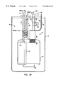
- FIG. 2 shows another preferred embodiment of the invention for ambulatory supplemental oxygen using a portable LOX dewar.
- FIG. 3 shows a typical temperature-composition diagram for oxygen-argon mixtures at typical dewar pressures.
- FIG. 4 shows a typical temperature-composition diagram for nitrogen-oxygen mixtures at typical dewar pressures.
- FIG. 5 shows typical oxygen concentration test data for gas streams into the condenser and out of the dewar during liquefaction, and out of the dewar as the liquid is re-vaporized.
- Oxygen source is a PSA oxygen concentrator.
- FIG. 6 shows the controller block diagram for operation of the system.
- FIGS. 7A through 7D are flow charts showing the controller logic.
- FIG. 8 shows the controller input levels and output states for the start-up mode of the preferred embodiment.
- FIG. 9 shows the controller input levels and output states for the condense mode of the preferred embodiment.
- FIG. 10 shows the controller input levels and output states for the transfer mode of the preferred embodiment.
- FIG. 11 shows the controller input levels and output state for the boil dry mode of the preferred embodiment.
- FIG. 12 illustrates basic components of a pulse tube refrigerator.
- FIG. 13 illustrates another embodiment of a cryocooler which may be used in the subject invention.
- FIG. 14 is a side cross-sectional view of the preferred embodiment of the condenser.
- FIG. 15 is an end cross-sectional view of the preferred embodiment of the condenser corresponding to FIG. 14 .
- FIG. 16 shows a side cross-sectional view of another preferred embodiment of the condenser.
- FIG. 17 shows an end cross-sectional view of another preferred embodiment of the condenser corresponding to FIG. 16 .
- FIG. 18 is an isometric view of the embodiment of the condenser shown in FIGS. 16 and 17.
- FIG. 19 is a cross-sectional view of an embodiment of a dewar having a liquefier with an integral vapor compression cycle coldhead, condenser, and recuperator, which is resistant to plugging and performance degradation caused by trace impurities in the gas stream such as water vapor, carbon dioxide and hydrocarbons.
- FIG. 20 is a cross-sectional view of an alternative embodiment of a dewar having a liquefier with an integral pulse tube or Sterling cycle coldhead, condenser, and recuperator, which is resistant to plugging and performance degradation caused by trace impurities in the gas stream such as water vapor, carbon dioxide and hydrocarbons.
- FIG. 21 is an end cross-sectional view, similar to FIG. 17, of an embodiment of a condenser having shaped fins to reduce the liquid film thickness.
- FIG. 22 is a block diagram of the invention in the medical oxygen preferred embodiment where gaseous oxygen is split off and liquefied for storage in a stationary dewar, similar to FIG. 1, and shows numerous means for transferring liquid oxygen from the storage dewar.
- FIG. 1 A flow chart of the preferred embodiment of the invention is set out in FIG. 1 .
- Its main components include an oxygen concentrator 11 , a cryocooler 12 , a condenser 13 , and a storage/collection dewar or vacuum insulated container 14 .
- the oxygen concentrator 11 operates on a pressure swing adsorption cycle and essentially strips all or most of the nitrogen from air along with other minor components such as H 2 O, CO 2 , CO, NO x , etc. The result is a stream of dry gas with high oxygen concentration ( ⁇ 92%) flowing in fluid outlet 50 .
- a portion of the gas from this output in fluid outlet 50 is routed to a condenser 13 in association with a cryocooler (or cryogenic refrigerator) 12 through flow lines 51 and 57 .
- the cryocooler provides cooling of the condenser heat exchanger 13 to liquefaction temperatures, causing the oxygen in contact therewith to go from the gaseous to the liquid phase.
- the condenser 13 typically must be insulated from ambient heating and may in practice even be located inside the dewar 14 .
- a recuperator 15 may be used to pre-cool the incoming stream utilizing the vent flow through line 52 out of the dewar as a cooling medium. In practice, this recuperator 15 may also be located within the dewar 14 to reduce ambient heating.
- Controller 16 may be equipped with a microprocessor, adequate memory, software and ancillary equipment comprising a computer which can be used to monitor and control the operation of the system.
- the controller 16 may be provided with signals from liquid level sensor 17 , oxygen sensor 18 , pressure transducer 9 , and temperature sensor 10 via lines 53 , 59 , 55 and 56 , respectively. These signals are sensed and processed by the computer, with the controller operating valve 19 , valve 25 , heater 21 , and cryocooler 12 , in accordance with predetermined programs.
- the controller also provides output indicators for the patient.
- the liquid level in the dewar is continuously displayed and the patient is alerted when the oxygen concentration is low and when the system is ready for them to transfer liquid to a portable dewar.
- a modem or wireless link may be included to enable remote monitoring of the key parameters of the system by the home care provider as well as information which is useful for repair, maintenance, billing, and statistical studies of patients for the medical oxygenation market.
- Key system parameters of interest include the number of liquid transfers performed, the oxygen concentration history, number of run hours on the cryocooler, and time of the last boil-dry as well as number of boil dries performed.
- the controller may include a computer and/or a microprocessor located either integrally with the liquefaction system claimed herein or remotely therefrom but in communication therewith using either a modem and telephone lines or with a wireless interface.
- the computer and/or microprocessor may include memory having a database, or may be remotely connected to a memory or database using a network.
- An Optimal Liquefaction Schedule for optimal operation of the liquefaction system is set out in FIGS. 7-10 and may be stored in the controller using the memory and database.
- the controller can sense optimum parameters of the system and optimally control, including by activating servomechanisms, liquefaction and transfer of liquid oxygen.
- Dewar 14 is equipped with a dip tube 20 and heater 21 .
- Heater 21 is used to build pressure in the dewar in order to expel liquid out the dip tube 20 when so desired.
- a quick disconnect valve 22 or other flow control means is located on the end of the dip tube. This allows connection of a portable LOX dewar 23 , which can then be carried by the patient requiring a mobile/ambulatory supply of oxygen.
- the dewar 14 could be eliminated and replaced with a portable dewar 23 which is modified slightly from those existing today.
- the new portable dewar would interface with the condenser 13 , recuperator 15 , and controller 16 .
- This embodiment requires a slightly different control scheme from that given for the preferred embodiment as the transfer and boil-dry modes are eliminated. Any small amount of accumulated water and hydrocarbons are eliminated from the portable dewar 23 after each use by allowing it to warm to room temperature before reuse.
- FIG. 1 In operation, in the preferred embodiment of FIG. 1, where a pressure swing adsorption (“PSA”) system is used, air is drawn into the oxygen concentrator 11 , where it is compressed by an oilless compressor, cooled, and passed through molecular sieve beds operating on the pressure swing adsorption cycle, as shown in U.S. Pat. Nos. 5,366,541; 5,112,367; 5,268,021 and Re. 35,009, which are incorporated herein by reference.
- This PSA system produces a 5-6 liters per minute (LPM) gas stream with high oxygen concentration at 3-7 pounds per square inch gauge (psig).
- LPM pounds per square inch gauge
- the composition of this gas stream varies but is typically 90-95% oxygen, 5-6% argon, 0-4% nitrogen, ⁇ 15 parts per million (ppm) water vapor, and ⁇ 1 ppm hydrocarbons. Exhaust from the PSA cycle (80-84% nitrogen, 15-19% oxygen, 0.6-0.8% argon, and trace amounts of water vapor, carbon dioxide and hydrocarbons) is vented into the atmosphere as waste gas.
- the high concentration oxygen stream in fluid outlet 50 is split with 0-4 lpm going through control valve 24 , for patient consumption, and 0.5-1.5 lpm through line 51 and control valve 19 for liquefaction.
- Oxygen sensor 18 monitors the oxygen concentration produced by oxygen concentrator 11 . If the oxygen concentration falls below 88%, controller 16 will close valve 19 and turn off the cryocooler 12 .
- the initial revaporized stream may have a reduced oxygen content because of the close boiling points of the components of the mixture.
- the temperature of the split gas stream entering the recuperator 15 is about room temperature. It is cooled to about 270 K (or colder) by the vent gas from the dewar flowing through the other side of the recuperator via line 52 .
- the recuperator 15 reduces the load on the cryocooler by using the cold vent gas to pre-cool the oxygen-rich gas stream flowing into the condenser 13 . From the recuperator 15 the high oxygen concentration stream flows through a line 57 to the condenser 13 , which is cooled to ⁇ 90 K by the cryocooler 12 .
- the condenser 13 provides cold surfaces to further cool and condense the flow. It is important to note that the gas passing through the condenser 13 is a mixture of oxygen, argon, and nitrogen. The normal boiling points of these components are: 90.18 K, 87.28 K, and 77.36 K respectively. Because of the close boiling points of the components of this mixture, there was initial skepticism because of the concern that all the nitrogen and argon would condense along with the oxygen.
- FIGS. 3 and 4 are temperature composition diagrams for binary mixtures of oxygen-argon and oxygen-nitrogen.
- FIGS. 3 and 4 are temperature composition diagrams for binary mixtures of oxygen-argon and oxygen-nitrogen.
- the upper curve at a given pressure defines the dew point and the lower curve defines the bubble point.
- FIG. 4 for a pressure of 0.101 MPa, if there is a gas mixture with 10 mole percent nitrogen (point 1 ), condensation will start when the gas has cooled to the dew point curve (point 2 g ) which is at a temperature of about 89.5 K in this case.
- the initial liquid formed (point 2 f ) will have only 7.4 mole percent nitrogen. If the temperature is lowered to point 3 , the liquid will have the composition of point 3 f while the remaining vapor will have the composition of point 3 g . As the temperature is lowered further to point 4 f or below, all of the mixture liquefies and the composition is 10 mole percent nitrogen, the same as at point 1 . If this liquid is heated, the nitrogen which has a lower boiling point will vaporize first. Thus, the composition of the first vapor formed will be that of point 4 g or about 30 mole percent. As the remaining liquid boils, the mole percent of nitrogen in the vapor drops back to 10 mole percent when point 2 g is reached.
- FIG. 5 shows typical oxygen concentration test data for condensing and re-vaporizing part of the product outlet stream from the oxygen concentrator 11 in the preferred embodiment.
- the system was cooling down without any net liquid accumulation in the dewar 14 . From this point up to about 500 minutes, condensation continued with liquid accumulation.
- the inlet stream to the condenser 13 had an oxygen concentration of 95%, while the vent flow through line 52 had an oxygen concentration of only 92-93%.
- the inlet stream and condenser cooling were stopped.
- the oxygen concentration of the re-vaporized liquid increased as the liquid boiled off due to the lower boiling point components (argon and nitrogen) boiling off first. This change in oxygen concentration presents no problem for medical ambulatory use because the oxygen concentration remains above 85%.
- the oxygen concentration will initially be much lower than that conventionally used in supplemental oxygen therapy (>85%). This can be accomplished by selecting the proper condenser temperature, which is a function of pressure, and by not condensing all of the incoming flow. If only part of the incoming flow (20-99%) is liquefied, the remainder of the flow will purge the vapor with higher impurity concentration from the system.
- a condenser temperature of about 90 K (for ⁇ 17 psia) minimizes the amount of argon and nitrogen liquefied without overly diminishing the yield of oxygen. Hence there will be both liquid and vapor leaving the condenser. The liquid will fall into the dewar 14 and collect. The vapor which has not condensed is vented to the atmosphere through line 52 and the recuperator 15 .
- the amount of incoming flow liquefied is controlled by setting the mass flow rate relative to the cooling capacity of the cryocooler.
- the parameters of the condenser and/or cryocooler can be stored in the memory of the controller and/or computer and the controller regulating the incoming flow depending on the parameters stored and/or sensed. Having a mass flow rate which exceeds the cooling capacity of the cryocooler/condenser combination, prevents the incoming flow from being completely liquefied.
- the mass flow rate is controlled by the amount of flow restriction between inlet valve 19 and flow control valve 25 . This includes the flow losses of the valves themselves as well as those in the recuperator, condenser, and all of the interconnecting plumbing.
- the pressure in the dewar 14 is maintained slightly above ambient pressure while the cryocooler is operating by valve 25 . It is desirable to keep the pressure in the condenser as high as possible because this increases the condensation temperature (as shown in FIGS. 3 and 4) which eases the requirements on the cryocooler. Once again this can be controlled by the controller and/or the computer, microprocessor and memory system.
- This pressure regulating function of the solenoid on-off valve 25 is accomplished by the pressure transducer 9 and controller 16 .
- a back pressure regulating valve such as a Tescom BB-3 series
- a suitable servomechanism may be used in lieu of the actively controlled solenoid. Liquid keeps accumulating in the dewar 14 until the liquid level sensor 17 signals the controller that the dewar is full or until the oxygen sensor 18 signals that the oxygen concentration of fluid exiting the oxygen concentrator 11 is too low.
- operating parameters for optimal operation of the system for the condenser should be that the condenser surface temperature should be in the range from 69.2-109.7 K and pressure should be in the range from 5-65 psia.
- the gas concentrations into the condenser for medical use should have oxygen in the range of 80-100%, nitrogen from 0-20%, and argon from 0-7%.
- the pressure in the dewar 14 must be increased so that liquid can be forced up the dip tube 20 .
- heater 21 is used for this purpose. Heater 21 may be immersed in the liquid oxygen or attached to the outer surface of the inner vessel.
- the controller 16 ensures that the cryocooler 12 is turned off and valve 25 is closed before the heater 21 is energized. The heater 21 remains turned on until the pressure, measured by pressure transducer 9 , reaches about 22 psig.
- An alternative means for transferring liquid by raising the pressure in the dewar 14 includes adding a compressor 300 between the oxygen concentrator 11 and the condenser 13 .
- the compressor 300 is preferably added in line 51 , either before or after valve 19 .
- the compressor 300 increases the pressure in the storage dewar 14 so that when the portable dewar 23 is engaged, liquid is forced up the dip tube 20 and into the portable dewar 23 .
- An additional benefit of adding a compressor 300 at this location is that it increases the pressure during liquefication in the dewar 14 , which increases the saturation temperature. An increased saturation temperature eases the cooling requirements on the cryocooler 12 .
- a further means for transferring liquid by raising the pressure in the dewar 14 includes using a high-pressure compressor 302 within the oxygen concentrator 11 instead of the typical low-pressure compressor.
- the high-pressure compressor 302 has the effect of increasing the pressure in the storage dewar 14 so that when the portable dewar 23 is engaged, liquid is forced up the dip tube 20 .
- a compressor 302 at this location slightly enhances the PSA cycle.
- a still further means for transferring liquid by raising the pressure in the dewar 14 includes using a vaporizer loop 304 .
- the dewar 14 preferably remains at low pressure while liquid is being produced.
- a valve 306 is opened to allow some liquid to flow into a coil 308 to be vaporized. This would increase the pressure in the dewar 14 so that liquid could be transferred to the portable dewar 23 .
- Another means for transferring liquid by raising the pressure in the dewar 14 includes a controllable heat leak such as a conductive strap 310 between ambient and the inner vessel of the dewar 14 .
- a controllable heat leak such as a conductive strap 310 between ambient and the inner vessel of the dewar 14 .
- Another means for transferring liquid by raising the pressure in the dewar 14 includes a controllable pump 312 that is actuated when transfer of liquid out of the dewar 14 is desired.
- An additional means for transferring liquid without raising the pressure in the dewar 14 includes incorporating a gravity-assisted dispensing mechanism 314 such as a controllable spigot (analogous to those used to dispense liquids from a large insulated cooler) near the bottom of the dewar 14 .
- a gravity-assisted dispensing mechanism 314 such as a controllable spigot (analogous to those used to dispense liquids from a large insulated cooler) near the bottom of the dewar 14 .
- the gravity-assisted dispensing mechanism eliminates the need for the dip tube 20 .
- the gravity-assisted dispensing mechanism 314 preferably includes a quick disconnect valve 316 or other flow control means, similar to disconnect valve 22 described above, located on the end of the mechanism 314 to allow for connection of a portable dewar 23 .
- An additional means for transferring liquid without raising the pressure in the dewar 14 includes incorporating a portable dewar 23 adapted to be filled from a pressure less than 20 psig, which is the standard for currently available home stationary liquid dewars.
- the portable dewar 23 may be adapted to be filled from a pressure such as 5 psig.
- a further means for transferring liquid without raising the pressure in the dewar 14 involves replacing the storage dewar 14 with a specially designed portable dewar 23 such as that described above with respect to FIG. 2, which interfaces with the rest of the home liquid oxygen ambulatory system.
- the dewar 14 , recuperator 15 , and condenser 13 will be warmed to room temperature periodically (preferably after about 30 fillings of a portable dewar, or every two months). This procedure is accomplished most economically when the inventory of liquid in the storage dewar is low; e.g. shortly after liquid transfer and a portable dewar has been filled.
- valve 19 will be closed, the cryocooler 12 is turned-off, valve 25 is open, and heater 21 is energized until all the liquid has boiled-off as evidenced by, for example, the temperature sensor 10 being above 125 K.
- the heater will boil-off the remaining liquid in the dewar 14 and with it any trace amounts of water and hydrocarbons which are condensed and solidified in the liquid oxygen or on the cold surfaces.
- valve 19 Once valve 19 is re-opened, the flow of concentrated oxygen gas purges and removes most of the water vapor and hydrocarbons from the liquefier.
- the heater 21 will remain turned on until the dewar temperature, measured by temperature sensor 10 , has warmed to about 300 K. Any remaining water vapor will be flushed out by gaseous oxygen during the subsequent cool-down.
- the dewpoint/frostpoint of the gas stream provided by the oxygen concentrator is below ⁇ 55° C.
- the mass of water flowing into the liquefier is quite small, the ice/frost formed at such a cold temperature has a very low density and hence, can take a appreciable volume of space that can lead to plugging of the liquefier. Therefore, the design of the recuperator 15 and/or condenser 13 must be able to allow for accumulation of frost without plugging.
- the liquefier 70 includes an integral coldhead 72 , condenser 74 and a recuperator 76 located generally within a dewar 14 .
- Incoming gaseous flow enters a neck tube 78 via an inlet 80 as shown by the arrows.
- the gaseous flow includes mostly oxygen gas along with a small amount of water vapor and other trace impurities.
- the gaseous flow is pre-cooled as it passes the helical recuperator 76 .
- the neck tube 78 has an inner diameter or dimension D and the helical recuperator 76 is constructed of a tube having an outer diameter or dimension d.
- inner diameter D of the neck tube 78 significantly larger than the outer diameter d of the helical recuperator tube 76 at locations along the neck tube 78 where incoming gaseous flow is present, the liquefier 70 allows for accumulation of frost on the inner surface 84 of the neck tube 78 or outer surface 82 of the recuperator 76 without plugging. This extends the period of time required between boil-dries without causing plugging in the liquefier 70 .
- the condenser 74 is shown in conjunction with a vapor compression cycle cryocooler 86 (evaporator 88 , tube-in-tube heat exchanger 90 , compressor 92 ) as its associated refrigerating mechanism. It will be readily understood by those skilled in the art that other refrigerating mechanisms may be used in conjunction with the condenser such as, but not by way of limitation, pulse tube, Stirling, etc.
- a condenser 94 may be used in conjunction with a coldhead 96 from a pulse tube cryocooler 97 to liquefy the incoming flow.
- the cryocooler 97 includes copper tubes 98 , 100 that provide strain relief via respective coils 102 , 104 .
- Copper tube 98 connects the coldhead 96 to a compressor 106 and copper tube 100 connects the coldhead 96 to a reservoir volume 108 .
- a flexible copper braid 110 provides a heat conduction path if needed to reject heat from the coldhead 96 .
- Vent gas enters the recuperator 76 through inlet 112 , as shown by the arrows, flows through the helical recuperator 76 (providing the aforementioned pre-cooling) and preferably exits to the atmosphere through outlet 114 .
- the dewar 14 may include a central liquid withdrawal tube 116 for withdrawing liquid oxygen from the dewar 14 .
- the central liquid withdrawal tube 116 may include an integral liquid level sensor 118 for monitoring the level of the liquid oxygen in the dewar 14 .
- a heater 21 may be attached to the outer surface of the inner vessel of the dewar 14 to assist in transferring liquid oxygen from the dewar 14 .
- a getter cup 120 such as those used in commercial cryogenic dewars may be attached to the inner vessel of the dewar 14 to maintain a high vacuum in the dewar 14 .
- the dewar, condenser, recuperator, and all associated hardware are at room temperature and must be cooled down. This is accomplished in the “start-up” mode, where valve 19 (see FIG. 1) is open, the heater is off, the cryocooler is on, and valve 25 is modulated to control the pressure/flow rate. It is desired to keep the pressure and hence the density of the gas as high as possible while maintaining the flow rate.
- the higher density gas will have better heat transfer with the dewar walls and associated hardware. It is noted that higher flow rates will enhance the convection heat transfer but may exceed the cooling capacity. Based on the cooling characteristics of the cryocooler between room temperature and 90 K, the flow rate can be changed to minimize the cool-down time.
- the dewar 14 is equipped with at least one relief valve 26 as a safety feature.
- Another relief valve 29 is provided and in communication with the inlet gas stream 51 , before flowing into the recuperator 15 . This serves as a back-up for relief valve 26 as well as providing a means to eliminate accumulated water from the recuperator 15 during periods when the cryocooler 12 is off, if valve 25 is closed.
- a check valve 27 is also provided to prevent backflow into the oxygen concentrator in the event of a malfunction.
- FIG. 6 provides a block diagram of the controller 16 control system with sensor input value ranges and output states. It also shows interfaces to an indicator and a modem or wireless interface.
- the mode switch 28 may be used by the patient to request the system to prepare for a liquid transfer to a portable dewar.
- the indicator then provides a visual signal that the system is building pressure in the dewar. Once the pressure has reached the desired value, a visual and/or audio signal is given to alert the patient that the system is ready to transfer liquid.
- the controller may also be programmed to perform an unattended liquid transfer.
- the modem, telephone line or wireless interface connections are optional hardware that may be added to the controller to enable remote monitoring of the system by the home care provider (e.g., to assist with maintenance and repair) or insurance companies or health providers/administrators (e.g., to assess if patients are using enough ambulatory oxygen to justify payments, etc.).
- the home care provider e.g., to assist with maintenance and repair
- insurance companies or health providers/administrators e.g., to assess if patients are using enough ambulatory oxygen to justify payments, etc.
- FIGS. 7A-D show a logic flow chart for the controller for the normal operation modes. This can also be referred to as the “input/output control schedule.”
- the mode switch 28 can also be used by a repair or factory technician to put the controller in a calibration mode which serves as a method to check and reset the program.
- the indicator provides liquid level readout, transfer request status, and low oxygen concentration information to the patient. All of the sensors are continuously scanned to provide the controller with the latest information.
- FIGS. 8 through 11 provide detailed output states as a function of input levels for the normal operating modes (start-up, condense, transfer, and boil-dry), which can be referred to as the “Optimal Liquefaction Operational Schedule.”
- FIG. 8 relates to the start-up mode; i.e., when the system is first turned on or after the boil-dry cycle.
- the liquid sensor 17 shows zero liquid volume in the dewar and, when the oxygen sensor 18 shows an oxygen concentration greater than 88%, valve 19 is open, heater 21 is off, cryocooler 12 is on, and the indicator or the controller indicates a cool-down state.
- Valve 25 is modulated to control pressure.
- the input to the controller 16 is such that when the oxygen sensor indicates oxygen concentration being greater than 88% and when the other criteria in the left-hand column of FIG. 9 are achieved, the output states set out in the right portion of the chart are attained.
- the liquid level sensor indicates a level of approximately 100%, causing closure of valves 19 and 25 , keeping the heater off, turning the cryocooler off, and having the indicator signal that the dewar is full.
- the transfer mode in FIG. 10 is the stage where one can fill the portable thermos bottles or dewars 23 from the main storage dewar 14 .
- the heater is activated, and when the pressure sensor indicates that the pressure exceeds 22 psig, as shown on the last line in the left-hand column of FIG. 10, the heater 21 is then turned off and the controller readout or indicator shows that the transfer of liquid oxygen can be made to the portable dewar.
- FIG. 11 indicates the boil-dry mode, with valve 25 open to allow the vapor to escape, and the various parameters relating thereto.
- FIG. 12 shows a schematic of a pulse tube refrigerator, the preferred embodiment of the cryocooler 12 in FIG. 1 .
- the pulse tube refrigerator is preferred for use in the subject ambulatory oxygen system because of its good efficiency with only one moving part, the pressure oscillator.
- Pulse tube refrigerators are shown in U.S. Pat. Nos. 5,488,830; 5,412,952 and 5,295,355 the disclosure of which are hereby incorporated by reference.
- FIG. 11 depicts a pulse tube refrigerator of the double inlet type.
- Other types of pulse tube refrigerators (PTR) could also be used such as the basic PTR or the inertance tube PTR (Zhu et al., 9 th International Cryocooler Conference, NH, June 1996).
- the double inlet pulse tube refrigerator as shown in FIG. 12 is comprised of a pressure oscillator 30 , primary heat rejecter 31 , regenerator 32 , heat acceptor 33 , pulse tube 34 , orifice rejecter 35 , bypass orifice 36 , primary orifice 37 , and reservoir volume 38 .
- the preferred refrigerant gas in the PTR closed and pressurized circuit is helium but various other gases such as neon or hydrogen could also be used.
- the PTR essentially pumps heat accepted at low temperature in the heat acceptor 33 to the orifice heat rejecter 35 where it is rejected at near ambient temperature.
- FIG. 12 depicts a “U-tube” configuration of the PTR, in-line and coaxial configurations are other possible options. Depicted therein is a piston type pressure oscillator, but other types are possible such as those utilizing diaphragms or bellows.
- FIG. 13 shows a schematic of another embodiment of the cryocooler.
- This is a vapor compression cycle cryocooler using a mixed gas refrigerant such as shown in U.S. Pat. No. 5,579,654; a 1969 German Patent by Fuderer & Andrija; British Patent No. 1,336,892.
- Other types of cryocoolers will work as long as they meet the important criteria of small size, convenience and low cost.
- the refrigerant is compressed by the compressor to high pressure. Then it is cooled by the aftercooler with heat Qh being rejected to the environment. Oil is separated in the oil separator. Oil flows back to the compressor inlet through a flow restriction.
- the refrigerant gas flows to a heat exchanger where it is cooled by the returning cold stream. Some components of the mixture may condense in this process.
- the liquid/gas refrigerant mixture flows through a throttle valve where its pressure is reduced and its temperature drops. This cold refrigerant enters the evaporator where the heat load Qc is absorbed and some liquid is boiled into vapor. This vapor flows up the cold side of the heat exchanger absorbing heat from the incoming stream. Then it flows back to the compressor. Heat Qc is accepted at cold temperature Tc. This is where the condenser would interface with the cryocooler.
- cryocooler it may be possible to remove some of the heat from the oxygen stream at a temperature warmer than Tc.
- FIGS. 14 and 15 One possible geometry of the generally vertically oriented, gravity assisted condenser 13 in FIG. 1 is shown in FIGS. 14 and 15.
- the incoming gas from the oxygen concentrator flows from conduit 57 to chamber 58 and then is distributed through an annular passage 59 between the outer tube 41 and inner rod 42 .
- the inner rod 42 is made of a high thermal conductivity material such as OFHC (Oxygen Free High Conductivity) copper, to minimize the temperature gradient between the surface on which the oxygen condenses ( 13 ) and the cryocooler 12 .
- the cold end of the cryocooler is shown by cross-hatched member 61 . Due to surface tension, the axial slots or grooves 43 will draw in liquid as it condenses.
- the mass flow rate is chosen to exceed the cooling capacity of the condenser/cryocooler so that only part of the incoming flow is liquefied. Also, the pressure in the condenser is maintained as high as possible while maintaining the desired flow rate. The higher pressure increases the condensation temperature which in turn reduces the requirements on the cryocooler.
- FIGS. 16 and 17 show another embodiment of the condenser that allows easier integration with the mixed gas refrigerant cryocooler. This configuration also allows access to the liquid in the dewar through the center of the condenser.
- the cold end of the cryocooler 45 is in thermal contact with an outer tube 46 and an inner tube 47 , both of which are made of a high thermal conductivity material such as OFHC copper and which utilize flanges 62 and 64 to interface with the cryocooler.
- the inner tube has axial slots or grooves 48 cut into its outer surface (see, FIG. 17) to increase the surface area and to wick condensed liquid, preventing a liquid film from forming over its entire surface. Gas enters the condenser through port 63 . The liquid and vapor flow down through an annular passage 49 .
- An isometric view of this embodiment is shown in FIG. 18 .
- FIG. 21 is a cross-sectional view, similar to the views in FIGS. 15 and 17, of another embodiment of a generally vertically oriented gravity assisted condenser 110 .
- the condenser 110 includes fins 112 and corresponding flutes 114 that extend vertically the longitudinal length of the condenser 110 on both an exterior side 116 and an interior side 118 of the condenser 110 , generally parallel with a vertical longitudinal axis L of the condenser 110 .
- the vertical longitudinally elongated fins 112 and flutes 114 enhance condensation by using surface tension forces to maintain a small liquid film thickness on the condensation surface.
- the fins 112 preferably have a convex surface with a hyperbolic cosine profile to provide a uniform liquid film thickness and maximize condensation; however, other simpler convex curved surfaces that are more easily manufactured can be used with only slightly less performance.
- a convex surface for the fins 112 produces a small liquid film thickness and a concave surface for the flute 114 supports or receives a larger liquid film thickness.
- the convex surfaces of the fins 112 can be drained by concave surfaces of the flutes 114 .
- the flutes 114 serve as drainage channels to keep the condensate from flooding the condensation surfaces.
- the flutes 114 may have a profile that is other than convex such as, but not by way of limitation, generally rectilinear or generally V-shaped.
- the fins 112 and flutes 114 may exist on only the exterior side 116 or interior side 118 of the condenser 110 .
- the condenser 110 may have fins 112 and flutes 114 on the interior and/or the exterior and the condenser 110 is used in conjunction with another condensing device such as another condenser located within the interior 118 and/or around the exterior 116 of the condenser 110 .
- the condenser 110 of the present invention may include fins 112 and flutes 114 on both sides 116 , 118 . Also, heat is conducted axially in the condenser 110 of the present invention.
Abstract
Description
Claims (30)
Priority Applications (2)
| Application Number | Priority Date | Filing Date | Title |
|---|---|---|---|
| US09/420,892 US6698423B1 (en) | 1997-06-16 | 1999-10-19 | Methods and apparatus to generate liquid ambulatory oxygen from an oxygen concentrator |
| US11/366,986 USRE43398E1 (en) | 1997-06-16 | 2006-03-01 | Methods and apparatus to generate liquid ambulatory oxygen from an oxygen concentrator |
Applications Claiming Priority (2)
| Application Number | Priority Date | Filing Date | Title |
|---|---|---|---|
| US08/876,970 US5979440A (en) | 1997-06-16 | 1997-06-16 | Methods and apparatus to generate liquid ambulatory oxygen from an oxygen concentrator |
| US09/420,892 US6698423B1 (en) | 1997-06-16 | 1999-10-19 | Methods and apparatus to generate liquid ambulatory oxygen from an oxygen concentrator |
Related Parent Applications (1)
| Application Number | Title | Priority Date | Filing Date |
|---|---|---|---|
| US08/876,970 Continuation-In-Part US5979440A (en) | 1997-06-16 | 1997-06-16 | Methods and apparatus to generate liquid ambulatory oxygen from an oxygen concentrator |
Related Child Applications (1)
| Application Number | Title | Priority Date | Filing Date |
|---|---|---|---|
| US11/366,986 Reissue USRE43398E1 (en) | 1997-06-16 | 2006-03-01 | Methods and apparatus to generate liquid ambulatory oxygen from an oxygen concentrator |
Publications (1)
| Publication Number | Publication Date |
|---|---|
| US6698423B1 true US6698423B1 (en) | 2004-03-02 |
Family
ID=25368984
Family Applications (5)
| Application Number | Title | Priority Date | Filing Date |
|---|---|---|---|
| US08/876,970 Expired - Lifetime US5979440A (en) | 1997-06-16 | 1997-06-16 | Methods and apparatus to generate liquid ambulatory oxygen from an oxygen concentrator |
| US09/342,890 Expired - Lifetime US6651653B1 (en) | 1997-06-16 | 1999-06-29 | Methods and apparatus to generate liquid ambulatory oxygen from an oxygen concentrator |
| US09/343,149 Expired - Lifetime US6681764B1 (en) | 1997-06-16 | 1999-06-29 | Methods and apparatus to generate liquid ambulatory oxygen from an oxygen concentrator |
| US09/420,892 Ceased US6698423B1 (en) | 1997-06-16 | 1999-10-19 | Methods and apparatus to generate liquid ambulatory oxygen from an oxygen concentrator |
| US11/366,986 Expired - Lifetime USRE43398E1 (en) | 1997-06-16 | 2006-03-01 | Methods and apparatus to generate liquid ambulatory oxygen from an oxygen concentrator |
Family Applications Before (3)
| Application Number | Title | Priority Date | Filing Date |
|---|---|---|---|
| US08/876,970 Expired - Lifetime US5979440A (en) | 1997-06-16 | 1997-06-16 | Methods and apparatus to generate liquid ambulatory oxygen from an oxygen concentrator |
| US09/342,890 Expired - Lifetime US6651653B1 (en) | 1997-06-16 | 1999-06-29 | Methods and apparatus to generate liquid ambulatory oxygen from an oxygen concentrator |
| US09/343,149 Expired - Lifetime US6681764B1 (en) | 1997-06-16 | 1999-06-29 | Methods and apparatus to generate liquid ambulatory oxygen from an oxygen concentrator |
Family Applications After (1)
| Application Number | Title | Priority Date | Filing Date |
|---|---|---|---|
| US11/366,986 Expired - Lifetime USRE43398E1 (en) | 1997-06-16 | 2006-03-01 | Methods and apparatus to generate liquid ambulatory oxygen from an oxygen concentrator |
Country Status (7)
| Country | Link |
|---|---|
| US (5) | US5979440A (en) |
| EP (1) | EP0990107B1 (en) |
| JP (2) | JP4183760B2 (en) |
| AT (1) | ATE200349T1 (en) |
| CA (1) | CA2293287C (en) |
| DE (1) | DE69800669T2 (en) |
| WO (1) | WO1998058219A1 (en) |
Cited By (98)
| Publication number | Priority date | Publication date | Assignee | Title |
|---|---|---|---|---|
| US20040079359A1 (en) * | 2002-10-24 | 2004-04-29 | Aylsworth Alonzo C. | Method and system for delivery of therapeutic gas to a patient and for filling a cylinder |
| US20040112066A1 (en) * | 2002-10-02 | 2004-06-17 | Kelly Leitch | High pressure CO2 purification and supply system |
| US20050274142A1 (en) * | 2004-06-14 | 2005-12-15 | Corey John A | Cryogenically producing oxygen-enriched liquid and/or gaseous oxygen from atmospheric air |
| US20060000223A1 (en) * | 2004-07-01 | 2006-01-05 | In-X Corporation | Desiccant cartridge |
| US20060086099A1 (en) * | 2004-10-26 | 2006-04-27 | In-X Corporation | Liquefying and storing a gas |
| US20060112693A1 (en) * | 2004-11-30 | 2006-06-01 | Sundel Timothy N | Method and apparatus for power generation using waste heat |
| US20060116036A1 (en) * | 2004-11-30 | 2006-06-01 | Sundel Timothy N | Method and apparatus for decreasing marine vessel power plant exhaust temperature |
| US20060130651A1 (en) * | 2004-12-22 | 2006-06-22 | Bizjak Travis A | Systems and methods for regulating heating assembly operation through pressure swing adsorption purge control |
| US20060130650A1 (en) * | 2004-12-20 | 2006-06-22 | Givens James A | Temperature-based breakthrough detection and pressure swing adsorption systems and fuel processing systems including the same |
| US20060130519A1 (en) * | 2004-11-08 | 2006-06-22 | Little William A | Small-scale gas liquefier |
| US20060157058A1 (en) * | 2005-01-18 | 2006-07-20 | Acoba, Llc | Trans-fill method and system |
| US20060174878A1 (en) * | 2005-02-09 | 2006-08-10 | Vbox, Incorporated | Low power ambulatory oxygen concentrator |
| US20060174874A1 (en) * | 2005-02-09 | 2006-08-10 | Vbox, Incorporated | Adsorbent cartridge for oxygen concentrator |
| US20060174881A1 (en) * | 2005-02-09 | 2006-08-10 | Vbox, Incorporated | Method of providing ambulatory oxygen |
| US20060174880A1 (en) * | 2005-02-09 | 2006-08-10 | Vbox, Incorporated | Ambulatory oxygen concentrator containing a three phase vacuum separation system |
| US20060174872A1 (en) * | 2005-02-09 | 2006-08-10 | Vbox, Incorporated | Method and apparatus for controlling the purity of oxygen produced by an oxygen concentrator |
| US20060174876A1 (en) * | 2005-02-09 | 2006-08-10 | Vbox, Incorporated | Personal oxygen concentrator |
| US20060174882A1 (en) * | 2005-02-09 | 2006-08-10 | Vbox, Incorporated | Method of controlling the rate of oxygen produced by an oxygen concentrator |
| US20060174871A1 (en) * | 2005-02-09 | 2006-08-10 | Vbox, Incorporated | Ambulatory oxygen concentrator with high efficiency adsorbent |
| US20060174877A1 (en) * | 2005-02-09 | 2006-08-10 | Vbox, Incorporated | Portable oxygen concentrator with a docking station |
| US20060174875A1 (en) * | 2005-02-09 | 2006-08-10 | Vbox, Incorporated | Ambulatory oxygen concentrator containing a power pack |
| US20060260358A1 (en) * | 2005-05-18 | 2006-11-23 | Kun Leslie C | Gas separation liquefaction means and processes |
| WO2006022975A3 (en) * | 2004-08-03 | 2006-11-30 | Sunpower Inc | Energy efficient, inexpensive extraction of oxygen from ambient air for portable and home use |
| US7171963B2 (en) | 2005-02-09 | 2007-02-06 | Vbox, Incorporated | Product pump for an oxygen concentrator |
| WO2007050097A2 (en) * | 2004-11-30 | 2007-05-03 | Carrier Corporation | Rankine cycle device having multiple turbo-generators |
| US20070214960A1 (en) * | 2006-03-16 | 2007-09-20 | Acoba, L.L.C. | Method and system of operating a trans-fill device |
| US20070214955A1 (en) * | 2006-03-16 | 2007-09-20 | Acoba, L.L.C. | Method and system of coordinating an intensifier and sieve beds |
| US20070227360A1 (en) * | 2006-04-03 | 2007-10-04 | Atlas Charles R | Portable oxygen concentrator |
| US20080053310A1 (en) * | 2006-04-03 | 2008-03-06 | Bliss Peter L | Compressors and methods for use |
| US20080140061A1 (en) * | 2006-09-08 | 2008-06-12 | Arbel Medical Ltd. | Method And Device For Combined Treatment |
| US20080148935A1 (en) * | 2004-12-20 | 2008-06-26 | Idatech, Llc | Temperature-based breakthrough detection and pressure swing adsorption systems and fuel processing systems including the same |
| US20080178610A1 (en) * | 2007-01-30 | 2008-07-31 | Douglas Whitcher | Portable Liquid Oxygen Storage Unit |
| US20080208181A1 (en) * | 2007-01-19 | 2008-08-28 | Arbel Medical Ltd. | Thermally Insulated Needles For Dermatological Applications |
| WO2008131080A1 (en) | 2007-04-20 | 2008-10-30 | Ric Investments, Llc | System and method for filling a portable liquified gas storage/delivery device |
| US20090019886A1 (en) * | 2007-07-20 | 2009-01-22 | Inspired Technologies, Inc. | Method and Apparatus for liquefaction of a Gas |
| US20090129946A1 (en) * | 2007-11-21 | 2009-05-21 | Arbel Medical, Ltd. | Pumping unit for delivery of liquid medium from a vessel |
| US20090151560A1 (en) * | 2007-12-12 | 2009-06-18 | Idatech, Llc | Systems and methods for supplying auxiliary fuel streams during intermittent byproduct discharge from pressure swing adsorption assemblies |
| US20090151249A1 (en) * | 2007-12-12 | 2009-06-18 | Adams Patton M | Systems and methods for supplying auxiliary fuel streams during intermittent byproduct discharge from pressure swing adsorption assemblies |
| US20090167698A1 (en) * | 2006-04-03 | 2009-07-02 | Altas Charles R | User interface for a portable oxygen concentrator |
| US20100162730A1 (en) * | 2007-06-14 | 2010-07-01 | Arbel Medical Ltd. | Siphon for delivery of liquid cryogen from dewar flask |
| US20100234670A1 (en) * | 2009-03-12 | 2010-09-16 | Eyal Shai | Combined cryotherapy and brachytherapy device and method |
| US20100281917A1 (en) * | 2008-11-05 | 2010-11-11 | Alexander Levin | Apparatus and Method for Condensing Contaminants for a Cryogenic System |
| US20100305439A1 (en) * | 2009-05-27 | 2010-12-02 | Eyal Shai | Device and Method for Three-Dimensional Guidance and Three-Dimensional Monitoring of Cryoablation |
| US20100307635A1 (en) * | 2007-10-22 | 2010-12-09 | Koninklijke Philips Electronics, N.V. | Liquid to high pressure gas transfill system and method |
| US20100324546A1 (en) * | 2007-07-09 | 2010-12-23 | Alexander Levin | Cryosheath |
| US20110015624A1 (en) * | 2008-01-15 | 2011-01-20 | Icecure Medical Ltd. | Cryosurgical instrument insulating system |
| US20110017063A1 (en) * | 2009-07-22 | 2011-01-27 | Van Brunt Nicholas P | Apparatus for separating oxygen from ambient air |
| US7938822B1 (en) | 2010-05-12 | 2011-05-10 | Icecure Medical Ltd. | Heating and cooling of cryosurgical instrument using a single cryogen |
| US7967815B1 (en) | 2010-03-25 | 2011-06-28 | Icecure Medical Ltd. | Cryosurgical instrument with enhanced heat transfer |
| US7967814B2 (en) | 2009-02-05 | 2011-06-28 | Icecure Medical Ltd. | Cryoprobe with vibrating mechanism |
| US8080005B1 (en) | 2010-06-10 | 2011-12-20 | Icecure Medical Ltd. | Closed loop cryosurgical pressure and flow regulated system |
| US8083733B2 (en) | 2008-04-16 | 2011-12-27 | Icecure Medical Ltd. | Cryosurgical instrument with enhanced heat exchange |
| US8136527B2 (en) | 2003-08-18 | 2012-03-20 | Breathe Technologies, Inc. | Method and device for non-invasive ventilation with nasal interface |
| US8335992B2 (en) | 2009-12-04 | 2012-12-18 | Nellcor Puritan Bennett Llc | Visual indication of settings changes on a ventilator graphical user interface |
| US8381729B2 (en) | 2003-06-18 | 2013-02-26 | Breathe Technologies, Inc. | Methods and devices for minimally invasive respiratory support |
| US8418694B2 (en) | 2003-08-11 | 2013-04-16 | Breathe Technologies, Inc. | Systems, methods and apparatus for respiratory support of a patient |
| US8443294B2 (en) | 2009-12-18 | 2013-05-14 | Covidien Lp | Visual indication of alarms on a ventilator graphical user interface |
| US8453645B2 (en) | 2006-09-26 | 2013-06-04 | Covidien Lp | Three-dimensional waveform display for a breathing assistance system |
| US8555882B2 (en) | 1997-03-14 | 2013-10-15 | Covidien Lp | Ventilator breath display and graphic user interface |
| US8567399B2 (en) | 2007-09-26 | 2013-10-29 | Breathe Technologies, Inc. | Methods and devices for providing inspiratory and expiratory flow relief during ventilation therapy |
| US8597198B2 (en) | 2006-04-21 | 2013-12-03 | Covidien Lp | Work of breathing display for a ventilation system |
| US8603228B2 (en) | 2010-09-07 | 2013-12-10 | Inova Labs, Inc. | Power management systems and methods for use in an oxygen concentrator |
| US8616207B2 (en) | 2010-09-07 | 2013-12-31 | Inova Labs, Inc. | Oxygen concentrator heat management system and method |
| US8677999B2 (en) | 2008-08-22 | 2014-03-25 | Breathe Technologies, Inc. | Methods and devices for providing mechanical ventilation with an open airway interface |
| US8702841B2 (en) * | 2012-04-17 | 2014-04-22 | Inogen, Inc. | Adsorber replacement notification for a portable gas concentrator |
| US8770193B2 (en) | 2008-04-18 | 2014-07-08 | Breathe Technologies, Inc. | Methods and devices for sensing respiration and controlling ventilator functions |
| US8770199B2 (en) | 2012-12-04 | 2014-07-08 | Ino Therapeutics Llc | Cannula for minimizing dilution of dosing during nitric oxide delivery |
| US8776793B2 (en) | 2008-04-18 | 2014-07-15 | Breathe Technologies, Inc. | Methods and devices for sensing respiration and controlling ventilator functions |
| US8794237B2 (en) | 2007-09-06 | 2014-08-05 | Inova Labs, Inc. | Oxygen concentrator apparatus and method having flow restricted coupling of the canisters |
| US8924878B2 (en) | 2009-12-04 | 2014-12-30 | Covidien Lp | Display and access to settings on a ventilator graphical user interface |
| US8925545B2 (en) | 2004-02-04 | 2015-01-06 | Breathe Technologies, Inc. | Methods and devices for treating sleep apnea |
| US8939152B2 (en) | 2010-09-30 | 2015-01-27 | Breathe Technologies, Inc. | Methods, systems and devices for humidifying a respiratory tract |
| WO2015017830A1 (en) * | 2013-08-02 | 2015-02-05 | Chart Inc. | Cryocooler with magnetic reciprocating piston |
| US8955518B2 (en) | 2003-06-18 | 2015-02-17 | Breathe Technologies, Inc. | Methods, systems and devices for improving ventilation in a lung area |
| US8985099B2 (en) | 2006-05-18 | 2015-03-24 | Breathe Technologies, Inc. | Tracheostoma spacer, tracheotomy method, and device for inserting a tracheostoma spacer |
| US9119925B2 (en) | 2009-12-04 | 2015-09-01 | Covidien Lp | Quick initiation of respiratory support via a ventilator user interface |
| US9132250B2 (en) | 2009-09-03 | 2015-09-15 | Breathe Technologies, Inc. | Methods, systems and devices for non-invasive ventilation including a non-sealing ventilation interface with an entrainment port and/or pressure feature |
| US9180270B2 (en) | 2009-04-02 | 2015-11-10 | Breathe Technologies, Inc. | Methods, systems and devices for non-invasive open ventilation with gas delivery nozzles within an outer tube |
| US9262588B2 (en) | 2009-12-18 | 2016-02-16 | Covidien Lp | Display of respiratory data graphs on a ventilator graphical user interface |
| US20160184772A1 (en) * | 2014-12-30 | 2016-06-30 | Pacific Consolidated Industries, Llc | High purity adsorption air separation unit |
| US9395046B2 (en) | 2007-10-22 | 2016-07-19 | Koninklijke Philips N.V. | Liquid to high pressure gas transfill system and method |
| US9440179B2 (en) | 2014-02-14 | 2016-09-13 | InovaLabs, LLC | Oxygen concentrator pump systems and methods |
| US9440180B2 (en) | 2012-10-12 | 2016-09-13 | Inova Labs, Llc | Oxygen concentrator systems and methods |
| US9440036B2 (en) | 2012-10-12 | 2016-09-13 | InovaLabs, LLC | Method and systems for the delivery of oxygen enriched gas |
| US9717876B2 (en) | 2012-10-12 | 2017-08-01 | Inova Labs, Inc. | Dual oxygen concentrator systems and methods |
| US9795756B2 (en) | 2012-12-04 | 2017-10-24 | Mallinckrodt Hospital Products IP Limited | Cannula for minimizing dilution of dosing during nitric oxide delivery |
| US9845920B2 (en) | 2011-03-14 | 2017-12-19 | Koninklijke Philips N.V. | Defroster for oxygen liquefier |
| US9889269B2 (en) | 2008-09-23 | 2018-02-13 | Caire Inc. | Systems and methods for generating liquid oxygen for portable use |
| US9950129B2 (en) | 2014-10-27 | 2018-04-24 | Covidien Lp | Ventilation triggering using change-point detection |
| US9962512B2 (en) | 2009-04-02 | 2018-05-08 | Breathe Technologies, Inc. | Methods, systems and devices for non-invasive ventilation including a non-sealing ventilation interface with a free space nozzle feature |
| US10058668B2 (en) | 2007-05-18 | 2018-08-28 | Breathe Technologies, Inc. | Methods and devices for sensing respiration and providing ventilation therapy |
| US10099028B2 (en) | 2010-08-16 | 2018-10-16 | Breathe Technologies, Inc. | Methods, systems and devices using LOX to provide ventilatory support |
| US10252020B2 (en) | 2008-10-01 | 2019-04-09 | Breathe Technologies, Inc. | Ventilator with biofeedback monitoring and control for improving patient activity and health |
| US10362967B2 (en) | 2012-07-09 | 2019-07-30 | Covidien Lp | Systems and methods for missed breath detection and indication |
| US11458274B2 (en) | 2016-05-03 | 2022-10-04 | Inova Labs, Inc. | Method and systems for the delivery of oxygen enriched gas |
| US11624556B2 (en) | 2019-05-06 | 2023-04-11 | Messer Industries Usa, Inc. | Impurity control for a high pressure CO2 purification and supply system |
| US11633224B2 (en) | 2020-02-10 | 2023-04-25 | Icecure Medical Ltd. | Cryogen pump |
| US11672934B2 (en) | 2020-05-12 | 2023-06-13 | Covidien Lp | Remote ventilator adjustment |
Families Citing this family (77)
| Publication number | Priority date | Publication date | Assignee | Title |
|---|---|---|---|---|
| JP3502389B2 (en) * | 1994-10-14 | 2004-03-02 | バード プロダクツ コーポレイション | Portable drag compressor driven mechanical ventilator |
| US5979440A (en) | 1997-06-16 | 1999-11-09 | Sequal Technologies, Inc. | Methods and apparatus to generate liquid ambulatory oxygen from an oxygen concentrator |
| US6347627B1 (en) * | 1998-04-23 | 2002-02-19 | Pioneer Inventions, Inc. | Nitrous oxide based oxygen supply system |
| US6446630B1 (en) * | 1999-02-11 | 2002-09-10 | Sunrise Medical Hhg Inc | Cylinder filling medical oxygen concentrator |
| FR2792210B1 (en) | 1999-04-13 | 2001-09-14 | Air Liquide Sante Int | PORTABLE MEDICAL EQUIPMENT FOR OXYGEN THERAPY AT HOME |
| ES2337546T3 (en) * | 1999-10-29 | 2010-04-27 | Chart Biomedical Distribution Llc | HIGH EFFICIENCY LIQUID STORAGE SYSTEM AND SUPPLY OF LIQUID OXYGEN. |
| ES2243320T3 (en) | 1999-10-29 | 2005-12-01 | Mallinckrodt Inc. | PORTABLE UNIT OF LIQUID OXYGEN WITH MULTIPLE FUNCTIONAL GUIDANCE. |
| US6742517B1 (en) | 1999-10-29 | 2004-06-01 | Mallinckrodt, Inc. | High efficiency liquid oxygen system |
| EP1239908B1 (en) | 1999-10-29 | 2006-10-04 | Mallinckrodt Inc. | Manifold for use in a portable liquid oxygen unit |
| US6212904B1 (en) * | 1999-11-01 | 2001-04-10 | In-X Corporation | Liquid oxygen production |
| FR2809329B1 (en) * | 2000-05-25 | 2002-08-16 | Air Liquide | PORTABLE OXYGEN CONCENTRATOR |
| US6336331B1 (en) * | 2000-08-01 | 2002-01-08 | Praxair Technology, Inc. | System for operating cryogenic liquid tankage |
| US6511526B2 (en) | 2001-01-12 | 2003-01-28 | Vbox, Incorporated | Pressure swing adsorption gas separation method and apparatus |
| FR2833188B1 (en) * | 2001-12-06 | 2004-05-21 | Air Liquide | INSTALLATION AND METHOD FOR PRODUCING PRODUCTS USING A FLUID |
| JP3726965B2 (en) * | 2002-07-01 | 2005-12-14 | 富士電機システムズ株式会社 | Oxygen production method and apparatus |
| US6668581B1 (en) * | 2002-10-30 | 2003-12-30 | Praxair Technology, Inc. | Cryogenic system for providing industrial gas to a use point |
| US20040197616A1 (en) * | 2003-04-01 | 2004-10-07 | Edlund David J. | Oxidant-enriched fuel cell system |
| DE10337138A1 (en) * | 2003-08-11 | 2005-03-17 | Freitag, Lutz, Dr. | Method and arrangement for the respiratory assistance of a patient as well as tracheal prosthesis and catheter |
| DE10334516B4 (en) * | 2003-07-29 | 2006-06-14 | Sorin Group Deutschland Gmbh | Display and operating device for medical devices and display / control unit therefor |
| US7059138B2 (en) * | 2003-09-23 | 2006-06-13 | Praxair Technology, Inc. | Biological refrigeration system |
| US20050072423A1 (en) | 2003-10-07 | 2005-04-07 | Deane Geoffrey Frank | Portable gas fractionalization system |
| US7066985B2 (en) | 2003-10-07 | 2006-06-27 | Inogen, Inc. | Portable gas fractionalization system |
| US7438745B2 (en) | 2003-10-07 | 2008-10-21 | Inogen, Inc. | Portable gas fractionalization system |
| US7135059B2 (en) | 2003-10-07 | 2006-11-14 | Inogen, Inc. | Portable gas fractionalization system |
| US7093479B2 (en) * | 2005-01-13 | 2006-08-22 | International Business Machines Corporation | Method and apparatus for indicating a parameter of transmitted fluid |
| US20060260327A1 (en) * | 2005-05-18 | 2006-11-23 | Shoji Kanamori | Apparatus and method for rapidly freezing small objects |
| US20070000258A1 (en) * | 2005-07-01 | 2007-01-04 | Bonaquist Dante P | Biological refrigeration sytem |
| US7721733B2 (en) * | 2005-07-29 | 2010-05-25 | Ric Investments, Llc | Portable liquid oxygen delivery system |
| US7686870B1 (en) | 2005-12-29 | 2010-03-30 | Inogen, Inc. | Expandable product rate portable gas fractionalization system |
| US7621269B2 (en) * | 2006-08-16 | 2009-11-24 | Rescue Air Systems, Inc. | Breathable air safety system and method having at least one fill site |
| US7527056B2 (en) * | 2006-08-16 | 2009-05-05 | Rescure Air Systems, Inc. | Breathable air safety system and method having an air storage sub-system |
| US7694678B2 (en) * | 2006-08-16 | 2010-04-13 | Rescue Air Systems, Inc. | Breathable air safety system and method having a fill station |
| US8733355B2 (en) * | 2006-08-16 | 2014-05-27 | Rescue Air Systems, Inc. | Breathable air safety system and method |
| US7673629B2 (en) * | 2006-08-16 | 2010-03-09 | Rescue Air Systems, Inc | Safety system and method of a tunnel structure |
| AU2007284343B2 (en) * | 2006-08-16 | 2014-03-27 | Rescue Air Systems, Inc. | Breathable air safety system and method having an air storage sub-system |
| US7677247B2 (en) * | 2006-08-16 | 2010-03-16 | Rescue Air Systems, Inc | Safety system and method of an underground mine |
| US7771511B2 (en) | 2006-08-28 | 2010-08-10 | Ric Investments, Llc | Oxygen concentration system and method |
| US20090030381A1 (en) * | 2007-07-23 | 2009-01-29 | Lind Casey J | Arced Hypodermic Needle |
| US8464542B2 (en) * | 2007-12-28 | 2013-06-18 | D-Wave Systems Inc. | Systems, methods, and apparatus for cryogenic refrigeration |
| CA2712481A1 (en) * | 2008-01-18 | 2009-07-23 | Breathe Technologies, Inc. | Methods and devices for improving efficacy of non-invasive ventilation |
| US8746248B2 (en) | 2008-03-31 | 2014-06-10 | Covidien Lp | Determination of patient circuit disconnect in leak-compensated ventilatory support |
| EP2313138B1 (en) | 2008-03-31 | 2018-09-12 | Covidien LP | System and method for determining ventilator leakage during stable periods within a breath |
| US8267085B2 (en) | 2009-03-20 | 2012-09-18 | Nellcor Puritan Bennett Llc | Leak-compensated proportional assist ventilation |
| US8272379B2 (en) | 2008-03-31 | 2012-09-25 | Nellcor Puritan Bennett, Llc | Leak-compensated flow triggering and cycling in medical ventilators |
| US20090255274A1 (en) * | 2008-04-14 | 2009-10-15 | Ungar Eugene K | System and method for recharging a high pressure gas storage container by transport of a low pressure cryogenic fluid |
| WO2010033373A2 (en) * | 2008-09-18 | 2010-03-25 | Nellcor Puritan Bennett Llc | Compact cryogenic cooling chamber for oxygen liquefaction system |
| US8109295B2 (en) * | 2008-10-24 | 2012-02-07 | Tyco Valves & Controls Lp | Manifold assembly |
| US9556029B2 (en) * | 2008-12-22 | 2017-01-31 | Koninklijke Philips N.V. | Liquid oxygen production device and method |
| US8402965B1 (en) | 2009-01-30 | 2013-03-26 | Essex Cryogenics Of Missouri, Inc. | Mass oxygen distribution system |
| US8424521B2 (en) | 2009-02-27 | 2013-04-23 | Covidien Lp | Leak-compensated respiratory mechanics estimation in medical ventilators |
| US8418691B2 (en) | 2009-03-20 | 2013-04-16 | Covidien Lp | Leak-compensated pressure regulated volume control ventilation |
| KR101030585B1 (en) | 2009-05-11 | 2011-04-21 | 신동옥 | Communication Device having oxygen supply function |
| US20110029910A1 (en) * | 2009-07-31 | 2011-02-03 | Nellcor Puritan Bennett Llc | Method And System For Providing A Graphical User Interface For Delivering A Low Flow Recruitment Maneuver |
| CN102762250B (en) | 2009-09-03 | 2017-09-26 | 呼吸科技公司 | Mthods, systems and devices for including the invasive ventilation with entrainment port and/or the non-tight vented interface of pressure characteristic |
| RU2012117598A (en) * | 2009-09-28 | 2013-11-20 | Конинклейке Филипс Элекроникс Н.В. | SYSTEM AND METHOD FOR LIQUIDATION AND STORAGE OF A FLUID |
| EP2483616A2 (en) * | 2009-09-28 | 2012-08-08 | Koninklijke Philips Electronics N.V. | System and method for liquefying and storing a fluid |
| EP2807437A2 (en) * | 2009-09-29 | 2014-12-03 | Koninklijke Philips N.V. | System and method for liquefying a fluid and storing the liquefied fluid |
| WO2011117765A2 (en) * | 2010-03-25 | 2011-09-29 | Koninklijke Philips Electronics N.V. | Controlling a oxygen liquefaction system responsive to a disturbance in supplied power |
| US9498589B2 (en) | 2011-12-31 | 2016-11-22 | Covidien Lp | Methods and systems for adaptive base flow and leak compensation |
| US9052129B2 (en) * | 2012-11-29 | 2015-06-09 | Luciano Faccin | Charging device for cooling system |
| US9517365B2 (en) * | 2013-03-15 | 2016-12-13 | Stephen JUAIRE | Portable oxygen system |
| US9675771B2 (en) | 2013-10-18 | 2017-06-13 | Covidien Lp | Methods and systems for leak estimation |
| FR3020450B1 (en) * | 2014-04-24 | 2016-05-20 | Air Liquide | LIQUID OXYGEN GENERATOR WITH THERMOELECTRIC COOLANT FOR HOME HEALTH |
| US10378803B2 (en) | 2014-08-08 | 2019-08-13 | D-Wave Systems Inc. | Systems and methods for electrostatic trapping of contaminants in cryogenic refrigeration systems |
| US9623982B2 (en) * | 2015-01-08 | 2017-04-18 | Airbus Group India Private Limited | On-board aircraft nitrogen enriched air and cooling fluid generation system and method |
| US20160201983A1 (en) * | 2015-01-08 | 2016-07-14 | AIRBUS GROUP INDIA PRIVATE LIMllTED | On-board aircraft oxygen enriched air and nitrogen enriched air generation system and method |
| CN107735135B (en) | 2015-04-02 | 2020-06-26 | 希尔-罗姆服务私人有限公司 | Manifold for a respiratory device |
| FR3035194A1 (en) | 2015-04-16 | 2016-10-21 | Air Liquide | OXYGEN SUPPLY INSTALLATION ASSOCIATING AN OXYGEN CONCENTRATOR WITH AN AUTONOMOUS GAS LIQUEFACTION DEVICE |
| WO2017075553A1 (en) | 2015-10-30 | 2017-05-04 | Richard Givens | Oxygen concentrating self-rescuer device |
| RU2666594C1 (en) * | 2017-03-28 | 2018-09-11 | Акционерное общество "Ассоциация разработчиков и производителей систем мониторинга" | Method of adaptation and restoration, training and regulating effect on a human organism |
| US10792449B2 (en) | 2017-10-03 | 2020-10-06 | Breathe Technologies, Inc. | Patient interface with integrated jet pump |
| KR20210005868A (en) * | 2018-03-24 | 2021-01-15 | 벨랴예프 블라디미르 | Breathing gas supply method, system and device |
| US11535407B1 (en) * | 2019-03-21 | 2022-12-27 | Advanced Cooling Technologies | Thermal management system |
| CN110260148A (en) * | 2019-06-28 | 2019-09-20 | 四川泰博流体科技有限公司 | A kind of storage facilities of liquid air, method and air liquefying apparatus |
| AU2021309952A1 (en) * | 2020-07-16 | 2023-03-16 | Ventec Life Systems, Inc. | System and method for concentrating gas |
| US11873757B1 (en) | 2022-05-24 | 2024-01-16 | Ray E. Combs | System for delivering oxygen to an internal combustion engine of a vehicle |
| CN115228124B (en) * | 2022-08-02 | 2023-05-09 | 安徽扬天金塑新能源装备有限公司 | Vacuum low-temperature gas purification device |
Citations (72)
| Publication number | Priority date | Publication date | Assignee | Title |
|---|---|---|---|---|
| US609499A (en) * | 1898-08-23 | chatwood | ||
| US621537A (en) * | 1899-03-21 | Apparatus for liquefying gas | ||
| US621536A (en) * | 1899-03-21 | Apparatus for liquefying air | ||
| US665912A (en) * | 1900-01-03 | 1901-01-15 | Emile Jolicard | Boiler. |
| US707633A (en) * | 1901-02-15 | 1902-08-26 | James F Place | Art or process of liquefying air or other gases and cooling by means thereof. |
| US718572A (en) * | 1902-02-17 | 1903-01-13 | Edwin Joseph Richardson | Apparatus for the liquefaction of air or other aeriform fluids. |
| US879302A (en) * | 1905-04-03 | 1908-02-18 | Colorado Iron Works Co | Blast-heating apparatus. |
| US881176A (en) * | 1906-02-23 | 1908-03-10 | Georges Claude | Apparatus for the liquefaction of air. |
| US948835A (en) * | 1910-02-08 | Bruce Walter | Ammonia-condenser. | |
| US1454053A (en) * | 1920-02-18 | 1923-05-08 | Griscom Russell Co | Oil cooler |
| US1782409A (en) * | 1927-12-19 | 1930-11-25 | Griscom Russell Co | Heat exchanger |
| US1796510A (en) * | 1929-06-17 | 1931-03-17 | Delas Francois Xavier J Albert | Surface condenser and the like |
| US1821080A (en) * | 1930-10-15 | 1931-09-01 | Engineering Products Corp Inc | Radiator |
| US1867163A (en) * | 1925-01-26 | 1932-07-12 | Louis Chavanne J | Heat recuperation |
| US1957006A (en) * | 1927-04-27 | 1934-05-01 | Sulphide Corp | Method of and apparatus for condensing sulphur |
| US2017676A (en) * | 1933-03-11 | 1935-10-15 | American Lurgi Corp | Method of and apparatus for condensing sulphuric acid |
| US2194654A (en) * | 1936-05-12 | 1940-03-26 | Hadamovsky Paul | Apparatus for liquefying gases |
| US2210031A (en) * | 1936-08-28 | 1940-08-06 | Pfaudler Co Inc | Refrigerating apparatus and method |
| US2318206A (en) * | 1940-06-17 | 1943-05-04 | M Werk Company | Apparatus for treating liquids flowing through heated tubes |
| US2384714A (en) * | 1943-04-12 | 1945-09-11 | Tech Studien Ag | Tubular heat exchanger |
| US2434519A (en) * | 1942-04-18 | 1948-01-13 | Raskin Walter | Heat exchange conduit with a spiral fin having a capillary groove |
| US2440245A (en) * | 1944-03-13 | 1948-04-27 | Standard Telephones Cables Ltd | Cooling of high-temperature bodies |
| US2751199A (en) * | 1951-04-18 | 1956-06-19 | Taco Heaters Inc | Heat exchanger |
| US2797554A (en) * | 1954-01-06 | 1957-07-02 | William J Donovan | Heat exchanger in refrigeration system |
| US2905447A (en) * | 1956-05-04 | 1959-09-22 | Huet Andre | Tubular heat-exchanger |
| US2937079A (en) * | 1956-08-06 | 1960-05-17 | Phillips Petroleum Co | Apparatus for contacting and subsequently separating immiscible liquids |
| US2943454A (en) * | 1958-06-30 | 1960-07-05 | Mine Safety Appliances Co | Liquid oxygen converter |
| US2945354A (en) * | 1957-03-18 | 1960-07-19 | North American Aviation Inc | Liquid oxygen conversion system |
| US2958204A (en) * | 1956-08-13 | 1960-11-01 | Aro Equipment Corp | Liquid oxygen converter |
| US2960834A (en) * | 1954-11-22 | 1960-11-22 | Garrett Corp | Production of liquid oxygen from atmospheric air |
| US2964919A (en) * | 1958-07-07 | 1960-12-20 | British Oxygen Co Ltd | Converter system for liquefied gases |
| US2969957A (en) * | 1956-01-10 | 1961-01-31 | Thomson Houston Comp Francaise | Electric discharge device cooling systems |
| US2970452A (en) * | 1959-04-01 | 1961-02-07 | Union Carbide Corp | Method and apparatus for supplying liquefied gas |
| US2993682A (en) * | 1957-03-18 | 1961-07-25 | Huet Andre | Heat exchanger tubes |
| US3055643A (en) * | 1956-08-06 | 1962-09-25 | Thomson Houston Comp Francaise | Heat exchangers |
| US3097497A (en) * | 1959-08-14 | 1963-07-16 | Normalair Ltd | Oxygen supply systems |
| US3117426A (en) * | 1960-11-23 | 1964-01-14 | Garrett Corp | Environmental system for protective suit |
| US3152589A (en) * | 1959-04-16 | 1964-10-13 | British Oxygen Co Ltd | Liquid oxygen system for passenger aircraft |
| US3183678A (en) * | 1963-04-29 | 1965-05-18 | Bendix Corp | Liquid to gas conversion system |
| US3186406A (en) * | 1959-02-21 | 1965-06-01 | Normalair Ltd | Breathing apparatus |
| US3199303A (en) * | 1963-05-09 | 1965-08-10 | Union Carbide Corp | Oxygen therapy system |
| US3205670A (en) * | 1962-09-24 | 1965-09-14 | Puritan Compressed Gas Corp | Oxygen supply system |
| US3318307A (en) * | 1964-08-03 | 1967-05-09 | Firewel Company Inc | Breathing pack for converting liquid air or oxygen into breathable gas |
| US3354664A (en) * | 1964-04-11 | 1967-11-28 | Philips Corp | Transferring condensed liquids to a storage container |
| US3400758A (en) * | 1966-05-16 | 1968-09-10 | United Aircraft Prod | Helical baffle means in a tubular heat exchanger |
| US3570481A (en) * | 1968-10-23 | 1971-03-16 | Cryogenic Systems Inc | Cryogenic underwater breathing apparatus |
| US3572048A (en) * | 1968-10-14 | 1971-03-23 | Wiremold Co | Ominpositional cryogenic underwater breathind apparatus |
| US3707078A (en) * | 1971-02-10 | 1972-12-26 | Bendix Corp | Fail-safe liquid oxygen to gaseous oxygen conversion system |
| US3749155A (en) * | 1970-07-16 | 1973-07-31 | Georges Claude Sa | Exchange process |
| US3797262A (en) * | 1972-12-01 | 1974-03-19 | Union Carbide Corp | Cryogenic fluid supply system |
| US3864928A (en) * | 1972-12-01 | 1975-02-11 | Union Carbide Corp | All-attitude cryogenic vapor vent system |
| US3983861A (en) * | 1975-08-21 | 1976-10-05 | Westman Manufacturing Company | Solar energy conversion device |
| US4211086A (en) * | 1977-10-11 | 1980-07-08 | Beatrice Foods Company | Cryogenic breathing system |
| US4253519A (en) * | 1979-06-22 | 1981-03-03 | Union Carbide Corporation | Enhancement for film condensation apparatus |
| US4360059A (en) * | 1977-10-01 | 1982-11-23 | Funke Warmeaustauscher Apparatebau Kg | Tube type heat exchanger |
| US4493368A (en) * | 1981-06-22 | 1985-01-15 | Norsk Hydro A.S. | Helical flow heat exchanger having individually adjustable baffles |
| US4513587A (en) * | 1981-09-14 | 1985-04-30 | Sueddeutsche Kuehlerfabrik Julius Fr. Behr Gmbh & Co., Kg | Evaporator particularly suitable for air conditioners in automotive vehicles |
| US4848447A (en) * | 1983-07-06 | 1989-07-18 | Sladky Hans | Tube-type heat exchanger and liquid distributor head therefor |
| US4850426A (en) * | 1987-10-29 | 1989-07-25 | Vicarb | Gas/liquid heat exchanger with condensation |
| US4899810A (en) * | 1987-10-22 | 1990-02-13 | General Electric Company | Low pressure drop condenser/heat pipe heat exchanger |
| US5048600A (en) * | 1990-10-10 | 1991-09-17 | T & G Technologies, Inc. | Condensor using both film-wise and drop-wise condensation |
| US5454429A (en) * | 1992-05-23 | 1995-10-03 | Neurauter; Peter | Rods and mandrel turbulators for heat exchanger |
| US5458190A (en) * | 1986-07-29 | 1995-10-17 | Showa Aluminum Corporation | Condenser |
| US5634517A (en) * | 1994-01-27 | 1997-06-03 | Siemens-Elema Ab | Device for reducing the relative humidity of a flowing gas |
| US5697228A (en) * | 1995-11-17 | 1997-12-16 | The Boc Group Plc | Gas manufacture |
| US5893275A (en) * | 1997-09-04 | 1999-04-13 | In-X Corporation | Compact small volume liquid oxygen production system |
| US5979440A (en) * | 1997-06-16 | 1999-11-09 | Sequal Technologies, Inc. | Methods and apparatus to generate liquid ambulatory oxygen from an oxygen concentrator |
| US6029473A (en) * | 1997-10-06 | 2000-02-29 | L'air Liquide, Societe Anonyme Pour L'etude Et L'exploitation Des Procedes Georges Claude | Process and installation for filling a reservoir under pressure |
| US6212904B1 (en) * | 1999-11-01 | 2001-04-10 | In-X Corporation | Liquid oxygen production |
| US6230518B1 (en) * | 1998-09-23 | 2001-05-15 | Linde Aktiengesellschaft | Process and liquefier for the production of liquid air |
| US6289981B1 (en) * | 1997-05-30 | 2001-09-18 | Showa Denko K.K. | Multi-bored flat tube for use in a heat exchanger and heat exchanger including said tubes |
| US6530421B1 (en) * | 1997-12-16 | 2003-03-11 | York International Corporation | Counterflow evaporator for refrigerants |
Family Cites Families (161)
| Publication number | Priority date | Publication date | Assignee | Title |
|---|---|---|---|---|
| US35099A (en) * | 1862-04-29 | Improvement in machines for boring seats of buggies | ||
| USRE19031E (en) | 1926-12-29 | 1933-12-19 | Process and apparatus for the | |
| US2919555A (en) | 1955-07-28 | 1960-01-05 | Joy Mfg Co | Apparatus for and method of separating gases |
| US2909903A (en) | 1956-11-07 | 1959-10-27 | Little Inc A | Liquefaction of low-boiling gases |
| US2944627A (en) * | 1958-02-12 | 1960-07-12 | Exxon Research Engineering Co | Method and apparatus for fractionating gaseous mixtures by adsorption |
| US3313091A (en) | 1963-11-04 | 1967-04-11 | Exxon Research Engineering Co | Vacuum cycle adsorption |
| US3807396A (en) * | 1967-03-16 | 1974-04-30 | E & M Labor | Life support system and method |
| GB1185199A (en) * | 1967-04-06 | 1970-03-25 | Firewell Company Inc | Breathing pack for converting liquid air or oxygen into breathing gas |
| US3552392A (en) * | 1968-07-01 | 1971-01-05 | Gen Electric | Aircraft closed circuit breathing system |
| US3714942A (en) * | 1969-02-03 | 1973-02-06 | Sub Marine Syst Inc | Cryogenic gas processing system |
| US3730178A (en) * | 1970-03-24 | 1973-05-01 | F Moreland | Deep-sea dive suit and life support system |
| US3837396A (en) * | 1970-09-11 | 1974-09-24 | Borg Warner | Vertical surface vapor condensers |
| US3710854A (en) * | 1971-02-17 | 1973-01-16 | Gen Electric | Condenser |
| GB1336892A (en) * | 1971-05-17 | 1973-11-14 | Nii Kriogennoi Elektroniki | Refrigerant for a cryogenic throttling unit |
| GB1416163A (en) * | 1972-01-07 | 1975-12-03 | Boc International Ltd | Air separation |
| US3924968A (en) | 1972-07-27 | 1975-12-09 | Gen Motors Corp | Radial compressor with muffled gas chambers and short stable piston skirts and method of assembling same |
| US3831594A (en) * | 1973-03-05 | 1974-08-27 | Us Navy | Life support system |
| US4017284A (en) | 1973-05-14 | 1977-04-12 | Cryox Corporation | Air distillation apparatus comprising regenerator means for producing oxygen |
| US3898047A (en) | 1973-07-17 | 1975-08-05 | Bendix Corp | Oxygen generation system |
| US3903962A (en) * | 1974-06-26 | 1975-09-09 | Borg Warner | Condensate guiding apparatus for vertical condensing tubes of vapor condenser |
| US3935715A (en) * | 1974-06-26 | 1976-02-03 | Borg-Warner Corporation | Vapor condenser for a refrigeration system |
| US3964866A (en) | 1974-09-13 | 1976-06-22 | William Barney Shelby | Helium reclamation |
| US4013429A (en) | 1975-06-04 | 1977-03-22 | Air Products And Chemicals, Inc. | Fractionation of air by adsorption |
| US4222750A (en) | 1976-08-16 | 1980-09-16 | Champion Spark Plug Company | Oxygen enrichment system for medical use |
| US4098303A (en) * | 1976-09-17 | 1978-07-04 | Robert Brown Associates | Vapor recovery system for loading backs and storage tanks |
| US4194890A (en) | 1976-11-26 | 1980-03-25 | Greene & Kellogg, Inc. | Pressure swing adsorption process and system for gas separation |
| US4181126A (en) * | 1978-01-23 | 1980-01-01 | Hendry Stephen M | Cryogenic, underwater-breathing apparatus |
| US4198213A (en) | 1978-01-26 | 1980-04-15 | The Garrett Corporation | Self adjusting oxygen enrichment system |
| US4263018A (en) | 1978-02-01 | 1981-04-21 | Greene & Kellogg | Pressure swing adsorption process and system for gas separation |
| US4194891A (en) * | 1978-12-27 | 1980-03-25 | Union Carbide Corporation | Multiple bed rapid pressure swing adsorption for oxygen |
| US4279127A (en) | 1979-03-02 | 1981-07-21 | Air Products And Chemicals, Inc. | Removable refrigerator for maintaining liquefied gas inventory |
| JPS55149620A (en) | 1979-05-11 | 1980-11-21 | Noboru Sato | Oxygen-enriching system having good rise-up characteristic |
| US4349357A (en) | 1980-06-23 | 1982-09-14 | Stanley Aviation Corporation | Apparatus and method for fractionating air and other gaseous mixtures |
| DE3029080A1 (en) | 1980-07-31 | 1982-02-18 | Linde Ag, 6200 Wiesbaden | METHOD AND DEVICE FOR PROVIDING BREATH GAS |
| EP0046369B2 (en) * | 1980-08-18 | 1990-02-28 | Normalair-Garrett (Holdings) Limited | Molecular sieve type gas separation systems |
| DE3120812C2 (en) | 1981-05-25 | 1984-04-19 | Siemens AG, 1000 Berlin und 8000 München | Radial piston compressor |
| US4529411A (en) | 1982-03-12 | 1985-07-16 | Standard Oil Company | CO2 Removal from high CO2 content hydrocarbon containing streams |
| US4542010A (en) | 1982-06-30 | 1985-09-17 | Bend Research, Inc. | Method and apparatus for producing oxygen and nitrogen and membrane therefor |
| US4516424A (en) | 1982-07-09 | 1985-05-14 | Hudson Oxygen Therapy Sales Company | Oxygen concentrator monitor and regulation assembly |
| US4627860A (en) * | 1982-07-09 | 1986-12-09 | Hudson Oxygen Therapy Sales Company | Oxygen concentrator and test apparatus |
| US4576616A (en) | 1982-07-27 | 1986-03-18 | Proto-Med. Inc. | Method and apparatus for concentrating oxygen |
| US4449990A (en) | 1982-09-10 | 1984-05-22 | Invacare Respiratory Corp. | Method and apparatus for fractioning oxygen |
| NL8204413A (en) | 1982-11-12 | 1984-06-01 | Hoek Mach Zuurstoff | SYSTEM FOR RECOGNIZING GAS BOTTLES. |
| FR2539629B1 (en) | 1983-01-26 | 1987-08-21 | Lemasne Sa | PROCESS FOR PRODUCING STERILE AIR FOR MEDICAL USE AND INSTALLATION FOR CARRYING OUT SAID METHOD |
| US4545790A (en) * | 1983-08-11 | 1985-10-08 | Bio-Care, Incorporated | Oxygen concentrator |
| DE3337572A1 (en) | 1983-10-15 | 1985-04-25 | Linde Ag, 6200 Wiesbaden | METHOD AND DEVICE FOR SEPARATING A COMPONENT FROM A GAS MIXTURE |
| US4610700A (en) | 1983-11-04 | 1986-09-09 | Union Carbide Corporation | Adsorbent composition useful in retarding corrosion in mufflers |
| US4602174A (en) | 1983-12-01 | 1986-07-22 | Sunpower, Inc. | Electromechanical transducer particularly suitable for a linear alternator driven by a free-piston stirling engine |
| US4510760A (en) | 1984-03-02 | 1985-04-16 | Messer Griesheim Industries, Inc. | Compact integrated gas phase separator and subcooler and process |
| NL8400990A (en) | 1984-03-29 | 1985-10-16 | Philips Nv | METHOD FOR LIQUEIFICATION OF A GAS AND LIQUEIFICATION PLANT FOR CARRYING OUT THE METHOD |
| US4552571A (en) | 1984-04-05 | 1985-11-12 | Vbm Corporation | Oxygen generator with two compressor stages |
| US4697635A (en) * | 1984-07-05 | 1987-10-06 | Apd Cryogenics Inc. | Parallel wrapped tube heat exchanger |
| US4827643A (en) | 1984-12-31 | 1989-05-09 | Aga Gas Central, Inc. | Identification device for a container |
| US4983190A (en) | 1985-05-21 | 1991-01-08 | Pall Corporation | Pressure-swing adsorption system and method for NBC collective protection |
| US4587967A (en) | 1985-07-09 | 1986-05-13 | Lifecare Services, Inc. | Oxygen enriched reciprocating piston respirator |
| US4583364A (en) | 1985-08-19 | 1986-04-22 | Sunpower, Inc. | Piston centering method and apparatus for free-piston Stirling engines |
| US4636226A (en) | 1985-08-26 | 1987-01-13 | Vbm Corporation | High pressure oxygen production system |
| US4870960A (en) * | 1985-10-07 | 1989-10-03 | Litton Systems, Inc. | Backup breathing gas supply for an oxygen concentrator system |
| JPH0621006B2 (en) * | 1985-12-23 | 1994-03-23 | 日本酸素株式会社 | High-concentration oxygen gas production equipment by pressure fluctuation adsorption method |
| US4785879A (en) * | 1986-01-14 | 1988-11-22 | Apd Cryogenics | Parallel wrapped tube heat exchanger |
| DE3601714A1 (en) | 1986-01-22 | 1987-07-23 | Draegerwerk Ag | DEVICE FOR ENRICHING BREATHING GAS WITH OXYGEN |
| US4706664A (en) | 1986-04-11 | 1987-11-17 | Puritan-Bennett Corporation | Inspiration oxygen saver |
| US4673415A (en) | 1986-05-22 | 1987-06-16 | Vbm Corporation | Oxygen production system with two stage oxygen pressurization |
| US4869733A (en) | 1986-05-22 | 1989-09-26 | Vbm Corporation | Super-enriched oxygen generator |
| EP0247365A3 (en) | 1986-05-30 | 1988-08-10 | Körber Ag | Filling apparatus for oxygen bottles for use in the medicinal oxygen therapy |
| US4698075A (en) | 1986-06-05 | 1987-10-06 | International Oxygen Company, Inc. | Control system for fluid absorption systems and the like |
| US4717406A (en) * | 1986-07-07 | 1988-01-05 | Liquid Air Corporation | Cryogenic liquified gas purification method and apparatus |
| US4704146A (en) * | 1986-07-31 | 1987-11-03 | Kryos Energy Inc. | Liquid carbon dioxide recovery from gas mixtures with methane |
| US4765804A (en) | 1986-10-01 | 1988-08-23 | The Boc Group, Inc. | PSA process and apparatus employing gaseous diffusion barriers |
| US4701187A (en) | 1986-11-03 | 1987-10-20 | Air Products And Chemicals, Inc. | Process for separating components of a gas stream |
| DE3712598A1 (en) | 1987-04-14 | 1988-10-27 | Siemens Ag | INHALATION ANESTHESIS DEVICE |
| US4822394A (en) * | 1987-09-14 | 1989-04-18 | Vertech Treatment Systems, Inc. | Method and apparatus for the production and liquefaction of gases |
| US4802899A (en) * | 1987-09-21 | 1989-02-07 | Airsep Corporation | Pressure swing adsorption apparatus |
| EP0312910B1 (en) | 1987-10-23 | 1993-03-10 | Teijin Limited | Oxygen enriching module and oxygen enriching apparatus using same |
| US4841732A (en) * | 1987-12-28 | 1989-06-27 | Sarcia Domenico S | System and apparatus for producing and storing liquid gases |
| ES2009156A6 (en) | 1988-01-11 | 1989-09-01 | Desarrollos Estudios Y Patente | Installation for the supply of oxygen in hospitals and the like. |
| US4826510A (en) * | 1988-01-13 | 1989-05-02 | The John Bunn Company | Portable low profile DC oxygen concentrator |
| US4957107A (en) | 1988-05-10 | 1990-09-18 | Sipin Anatole J | Gas delivery means |
| US4948391A (en) | 1988-05-12 | 1990-08-14 | Vacuum Optics Corporation Of Japan | Pressure swing adsorption process for gas separation |
| DE3817092A1 (en) | 1988-05-19 | 1989-11-30 | Draegerwerk Ag | CONVEYOR DEVICE FOR SUPPLYING A VENTILATOR WITH BREATHING GAS |
| US4867766A (en) | 1988-09-12 | 1989-09-19 | Union Carbide Corporation | Oxygen enriched air system |
| US5002591A (en) * | 1988-10-14 | 1991-03-26 | Vbm Corporation | High efficiency PSA gas concentrator |
| US4880443A (en) * | 1988-12-22 | 1989-11-14 | The United States Of America As Represented By The Secretary Of The Air Force | Molecular sieve oxygen concentrator with secondary oxygen purifier |
| US4979882A (en) | 1989-03-13 | 1990-12-25 | Wisconsin Alumni Research Foundation | Spherical rotary machine having six rotary pistons |
| US5144945A (en) | 1989-04-20 | 1992-09-08 | Nippon Sanso Kabushiki Kaisha | Portable oxygen-enriching air inhaler |
| FR2647431B1 (en) | 1989-05-24 | 1991-08-16 | Air Liquide | PROCESS AND PLANT FOR THE PRODUCTION OF HIGH-PRESSURE GASEOUS OXYGEN |
| US5071453A (en) * | 1989-09-28 | 1991-12-10 | Litton Systems, Inc. | Oxygen concentrator with pressure booster and oxygen concentration monitoring |
| US5112367A (en) * | 1989-11-20 | 1992-05-12 | Hill Charles C | Fluid fractionator |
| US5268021A (en) * | 1989-11-20 | 1993-12-07 | Dynotec Corporation | Fluid fractionator |
| US5154737A (en) | 1990-01-12 | 1992-10-13 | Vbm Corporation | System for eliminating air leakage and high purity oxygen of a PSA oxygen concentrator |
| US4971609A (en) * | 1990-02-05 | 1990-11-20 | Pawlos Robert A | Portable oxygen concentrator |
| GB9003033D0 (en) | 1990-02-10 | 1990-04-11 | Normalair Garrett Ltd | Oxygen-rich gas breathing systems |
| US5076823A (en) * | 1990-03-20 | 1991-12-31 | Air Products And Chemicals, Inc. | Process for cryogenic air separation |
| US5237987A (en) | 1990-06-07 | 1993-08-24 | Infrasonics, Inc. | Human lung ventilator system |
| JPH089992B2 (en) | 1990-06-19 | 1996-01-31 | トキコ株式会社 | Multi-stage compressor |
| US5060480A (en) | 1990-10-30 | 1991-10-29 | L'air Liquide, Societe Anonyme Pour L'etude Et L'exploitation Des Procedes Georges Claude | Process and apparatus for the liquefaction of a flow of gaseous oxygen |
| US5163297A (en) * | 1991-01-15 | 1992-11-17 | Iwatani International Corporation | Device for preventing evaporation of liquefied gas in a liquefied gas reservoir |
| DE4106547A1 (en) * | 1991-03-01 | 1992-09-03 | Bayer Ag | METHOD FOR OXYGEN ENRICHMENT |
| US5163978A (en) | 1991-10-08 | 1992-11-17 | Praxair Technology, Inc. | Dual product pressure swing adsorption process and system |
| US5207806A (en) | 1991-10-08 | 1993-05-04 | Praxair Technology, Inc. | Dual product pressure swing adsorption and membrane operations |
| GB9124156D0 (en) | 1991-11-14 | 1992-01-08 | Boc Group Plc | Compressing oxygen |
| FR2685519A1 (en) | 1991-12-20 | 1993-06-25 | Gemplus Card Int | SYSTEM FOR THE IDENTIFICATION OF CONTAINERS, ESPECIALLY GAS BOTTLES. |
| DE4205412C2 (en) * | 1992-02-22 | 1994-04-14 | Draegerwerk Ag | Respirator with liquefied breathing gas |
| US5361591A (en) * | 1992-04-15 | 1994-11-08 | Oceaneering International, Inc. | Portable life support system |
| US6089226A (en) * | 1996-11-22 | 2000-07-18 | Aerospace Design & Development, Inc. | Self contained, cryogenic mixed gas single phase storage and delivery |
| US5709203A (en) * | 1992-05-07 | 1998-01-20 | Aerospace Design And Development, Inc. | Self contained, cryogenic mixed gas single phase storage and delivery system and method for body cooling, gas conditioning and utilization |
| US5231835A (en) * | 1992-06-05 | 1993-08-03 | Praxair Technology, Inc. | Liquefier process |
| US5271231A (en) * | 1992-08-10 | 1993-12-21 | L'air Liquide, Societe Anonyme Pour L'etude Et L'exploitation Des Procedes Georges Claude | Method and apparatus for gas liquefaction with plural work expansion of feed as refrigerant and air separation cycle embodying the same |
| JPH0726784B2 (en) * | 1992-09-25 | 1995-03-29 | 岩谷産業株式会社 | Simple liquid nitrogen production equipment |
| GB2272492B (en) | 1992-11-11 | 1996-05-01 | Dowty Defence & Air Syst | Gas supply apparatus |
| CA2109017A1 (en) * | 1992-12-16 | 1994-06-17 | Donald M. Smith | Method and apparatus for the intermittent delivery of oxygen therapy to a person |
| US5388413A (en) | 1993-01-22 | 1995-02-14 | Major; Thomas O. | Portable nitrogen source |
| EP0609620B1 (en) | 1993-01-30 | 1999-02-10 | The BOC Group plc | Gas separation |
| US5342176A (en) | 1993-04-05 | 1994-08-30 | Sunpower, Inc. | Method and apparatus for measuring piston position in a free piston compressor |
| EP0626516B1 (en) | 1993-04-15 | 1997-06-04 | KNF Neuberger GmbH | Lubricant-free vacuum pump arrangement |
| US5337572A (en) * | 1993-05-04 | 1994-08-16 | Apd Cryogenics, Inc. | Cryogenic refrigerator with single stage compressor |
| US5354361A (en) | 1993-05-28 | 1994-10-11 | Litton Industries, Inc. | Energy recovering pressure balance scheme for a combination pressure swing absorber with a boost compressor |
| FR2709537B1 (en) * | 1993-09-01 | 1995-10-13 | Air Liquide | Process and installation for producing oxygen and / or nitrogen gas under pressure. |
| US5441658A (en) * | 1993-11-09 | 1995-08-15 | Apd Cryogenics, Inc. | Cryogenic mixed gas refrigerant for operation within temperature ranges of 80°K- 100°K |
| US5525845A (en) | 1994-03-21 | 1996-06-11 | Sunpower, Inc. | Fluid bearing with compliant linkage for centering reciprocating bodies |
| US5474595A (en) * | 1994-04-25 | 1995-12-12 | Airsep Corporation | Capacity control system for pressure swing adsorption apparatus and associated method |
| US5519999A (en) * | 1994-08-05 | 1996-05-28 | Trw Inc. | Flow turning cryogenic heat exchanger |
| US5461859A (en) | 1994-09-08 | 1995-10-31 | Sunpower, Inc. | Centering system with one way valve for free piston machine |
| US5555655A (en) | 1994-09-26 | 1996-09-17 | Aga Ab | Identification device for a container |
| US5593478A (en) | 1994-09-28 | 1997-01-14 | Sequal Technologies, Inc. | Fluid fractionator |
| US5531807A (en) * | 1994-11-30 | 1996-07-02 | Airsep Corporation | Apparatus and method for supplying oxygen to passengers on board aircraft |
| US5704964A (en) | 1994-12-27 | 1998-01-06 | Nippon Sanso Corporation | Pressure swing adsorption process |
| US5558139A (en) * | 1995-02-13 | 1996-09-24 | Essex Cryogenics Of Missouri | Liquid oxygen system |
| US5726908A (en) * | 1995-03-20 | 1998-03-10 | Figgie International Inc. | Liquid quantity sensor and method |
| US6012453A (en) * | 1995-04-20 | 2000-01-11 | Figgie Inernational Inc. | Apparatus for withdrawal of liquid from a container and method |
| US5572880A (en) * | 1995-04-21 | 1996-11-12 | Figgie International Inc. | Apparatus for providing a conditioned airflow inside a microenvironment and method |
| US5579654A (en) * | 1995-06-29 | 1996-12-03 | Apd Cryogenics, Inc. | Cryostat refrigeration system using mixed refrigerants in a closed vapor compression cycle having a fixed flow restrictor |
| US5595065A (en) * | 1995-07-07 | 1997-01-21 | Apd Cryogenics | Closed cycle cryogenic refrigeration system with automatic variable flow area throttling device |
| US5593291A (en) | 1995-07-25 | 1997-01-14 | Thomas Industries Inc. | Fluid pumping apparatus |
| US5678536A (en) * | 1995-09-05 | 1997-10-21 | The United States Of America As Represented By The Administrator Of The National Aeronautics And Space Administration | Liquid air mixing system |
| US5584194A (en) * | 1995-10-31 | 1996-12-17 | Gardner; Thomas W. | Method and apparatus for producing liquid nitrogen |
| US5823186A (en) | 1996-06-20 | 1998-10-20 | Dragerwerk Ag | Respirator |
| DE29612942U1 (en) | 1996-07-30 | 1997-09-04 | Weh Verbindungstechnik | Quick connection coupling |
| US5827358A (en) * | 1996-11-08 | 1998-10-27 | Impact Mst, Incorporation | Rapid cycle pressure swing adsorption oxygen concentration method and apparatus |
| US5858062A (en) | 1997-02-10 | 1999-01-12 | Litton Systems, Inc. | Oxygen concentrator |
| JP3527609B2 (en) * | 1997-03-13 | 2004-05-17 | 株式会社神戸製鋼所 | Air separation method and apparatus |
| DE19714644C2 (en) | 1997-04-09 | 1999-09-02 | Draegerwerk Ag | Gas delivery device for ventilators and anesthetic devices and their use |
| US5901758A (en) | 1997-04-30 | 1999-05-11 | The Boc Group, Inc. | Method of filling gas containers |
| US6092993A (en) | 1997-08-14 | 2000-07-25 | Bristol Compressors, Inc. | Adjustable crankpin throw structure having improved throw stabilizing means |
| KR19990028153A (en) * | 1997-09-30 | 1999-04-15 | 정휘동 | Portable PS Oxygen Generator |
| US5988165A (en) | 1997-10-01 | 1999-11-23 | Invacare Corporation | Apparatus and method for forming oxygen-enriched gas and compression thereof for high-pressure mobile storage utilization |
| US6079459A (en) | 1998-02-11 | 2000-06-27 | Welding Company Of America | Controller for tank-filling system |
| US6446630B1 (en) * | 1999-02-11 | 2002-09-10 | Sunrise Medical Hhg Inc | Cylinder filling medical oxygen concentrator |
| FR2792210B1 (en) * | 1999-04-13 | 2001-09-14 | Air Liquide Sante Int | PORTABLE MEDICAL EQUIPMENT FOR OXYGEN THERAPY AT HOME |
| DE19958532C1 (en) | 1999-05-18 | 2001-01-18 | Draeger Medizintech Gmbh | Respiration apparatus uses gas volume sensors coupled to measuring and regulating device for gas feed element and controlled blocking valve for supplying patient with defined respiration gas volume |
| US6393802B1 (en) | 1999-12-22 | 2002-05-28 | Sunrise Medical Hhg, Inc. | Cylinder filler for use with an oxygen concentrator |
| US6230516B1 (en) * | 2000-02-04 | 2001-05-15 | Andonian Family Nominee Trust | Apparatus for mixing a multiple constituent liquid into a container and method |
| US6342090B1 (en) | 2000-05-16 | 2002-01-29 | Litton Systems, Inc. | Gas generating system with multi-rate charging feature |
| FR2809329B1 (en) * | 2000-05-25 | 2002-08-16 | Air Liquide | PORTABLE OXYGEN CONCENTRATOR |
| US6651658B1 (en) | 2000-08-03 | 2003-11-25 | Sequal Technologies, Inc. | Portable oxygen concentration system and method of using the same |
| US6719019B2 (en) | 2002-06-28 | 2004-04-13 | Litton Systems, Inc. | Deployable oxygen charging system |
| US6904913B2 (en) | 2002-10-24 | 2005-06-14 | Acoba, Llc | Method and system for delivery of therapeutic gas to a patient and for filling a cylinder |
| US6889726B2 (en) | 2002-10-25 | 2005-05-10 | Invacare Corporation | Method and apparatus for filling portable high pressure cylinders with respiratory oxygen |
| US20050072423A1 (en) | 2003-10-07 | 2005-04-07 | Deane Geoffrey Frank | Portable gas fractionalization system |
| CA2548364A1 (en) | 2003-12-17 | 2005-06-30 | Invacare Corporation | Oxygen supply system |
| US20050274142A1 (en) | 2004-06-14 | 2005-12-15 | Corey John A | Cryogenically producing oxygen-enriched liquid and/or gaseous oxygen from atmospheric air |
-
1997
- 1997-06-16 US US08/876,970 patent/US5979440A/en not_active Expired - Lifetime
-
1998
- 1998-06-03 WO PCT/US1998/011154 patent/WO1998058219A1/en active IP Right Grant
- 1998-06-03 AT AT98926158T patent/ATE200349T1/en not_active IP Right Cessation
- 1998-06-03 DE DE69800669T patent/DE69800669T2/en not_active Expired - Lifetime
- 1998-06-03 CA CA002293287A patent/CA2293287C/en not_active Expired - Lifetime
- 1998-06-03 JP JP50445499A patent/JP4183760B2/en not_active Expired - Lifetime
- 1998-06-03 EP EP98926158A patent/EP0990107B1/en not_active Expired - Lifetime
-
1999
- 1999-06-29 US US09/342,890 patent/US6651653B1/en not_active Expired - Lifetime
- 1999-06-29 US US09/343,149 patent/US6681764B1/en not_active Expired - Lifetime
- 1999-10-19 US US09/420,892 patent/US6698423B1/en not_active Ceased
-
2006
- 2006-03-01 US US11/366,986 patent/USRE43398E1/en not_active Expired - Lifetime
-
2008
- 2008-04-11 JP JP2008103219A patent/JP4729593B2/en not_active Expired - Lifetime
Patent Citations (72)
| Publication number | Priority date | Publication date | Assignee | Title |
|---|---|---|---|---|
| US948835A (en) * | 1910-02-08 | Bruce Walter | Ammonia-condenser. | |
| US621537A (en) * | 1899-03-21 | Apparatus for liquefying gas | ||
| US621536A (en) * | 1899-03-21 | Apparatus for liquefying air | ||
| US609499A (en) * | 1898-08-23 | chatwood | ||
| US665912A (en) * | 1900-01-03 | 1901-01-15 | Emile Jolicard | Boiler. |
| US707633A (en) * | 1901-02-15 | 1902-08-26 | James F Place | Art or process of liquefying air or other gases and cooling by means thereof. |
| US718572A (en) * | 1902-02-17 | 1903-01-13 | Edwin Joseph Richardson | Apparatus for the liquefaction of air or other aeriform fluids. |
| US879302A (en) * | 1905-04-03 | 1908-02-18 | Colorado Iron Works Co | Blast-heating apparatus. |
| US881176A (en) * | 1906-02-23 | 1908-03-10 | Georges Claude | Apparatus for the liquefaction of air. |
| US1454053A (en) * | 1920-02-18 | 1923-05-08 | Griscom Russell Co | Oil cooler |
| US1867163A (en) * | 1925-01-26 | 1932-07-12 | Louis Chavanne J | Heat recuperation |
| US1957006A (en) * | 1927-04-27 | 1934-05-01 | Sulphide Corp | Method of and apparatus for condensing sulphur |
| US1782409A (en) * | 1927-12-19 | 1930-11-25 | Griscom Russell Co | Heat exchanger |
| US1796510A (en) * | 1929-06-17 | 1931-03-17 | Delas Francois Xavier J Albert | Surface condenser and the like |
| US1821080A (en) * | 1930-10-15 | 1931-09-01 | Engineering Products Corp Inc | Radiator |
| US2017676A (en) * | 1933-03-11 | 1935-10-15 | American Lurgi Corp | Method of and apparatus for condensing sulphuric acid |
| US2194654A (en) * | 1936-05-12 | 1940-03-26 | Hadamovsky Paul | Apparatus for liquefying gases |
| US2210031A (en) * | 1936-08-28 | 1940-08-06 | Pfaudler Co Inc | Refrigerating apparatus and method |
| US2318206A (en) * | 1940-06-17 | 1943-05-04 | M Werk Company | Apparatus for treating liquids flowing through heated tubes |
| US2434519A (en) * | 1942-04-18 | 1948-01-13 | Raskin Walter | Heat exchange conduit with a spiral fin having a capillary groove |
| US2384714A (en) * | 1943-04-12 | 1945-09-11 | Tech Studien Ag | Tubular heat exchanger |
| US2440245A (en) * | 1944-03-13 | 1948-04-27 | Standard Telephones Cables Ltd | Cooling of high-temperature bodies |
| US2751199A (en) * | 1951-04-18 | 1956-06-19 | Taco Heaters Inc | Heat exchanger |
| US2797554A (en) * | 1954-01-06 | 1957-07-02 | William J Donovan | Heat exchanger in refrigeration system |
| US2960834A (en) * | 1954-11-22 | 1960-11-22 | Garrett Corp | Production of liquid oxygen from atmospheric air |
| US2969957A (en) * | 1956-01-10 | 1961-01-31 | Thomson Houston Comp Francaise | Electric discharge device cooling systems |
| US2905447A (en) * | 1956-05-04 | 1959-09-22 | Huet Andre | Tubular heat-exchanger |
| US2937079A (en) * | 1956-08-06 | 1960-05-17 | Phillips Petroleum Co | Apparatus for contacting and subsequently separating immiscible liquids |
| US3055643A (en) * | 1956-08-06 | 1962-09-25 | Thomson Houston Comp Francaise | Heat exchangers |
| US2958204A (en) * | 1956-08-13 | 1960-11-01 | Aro Equipment Corp | Liquid oxygen converter |
| US2945354A (en) * | 1957-03-18 | 1960-07-19 | North American Aviation Inc | Liquid oxygen conversion system |
| US2993682A (en) * | 1957-03-18 | 1961-07-25 | Huet Andre | Heat exchanger tubes |
| US2943454A (en) * | 1958-06-30 | 1960-07-05 | Mine Safety Appliances Co | Liquid oxygen converter |
| US2964919A (en) * | 1958-07-07 | 1960-12-20 | British Oxygen Co Ltd | Converter system for liquefied gases |
| US3186406A (en) * | 1959-02-21 | 1965-06-01 | Normalair Ltd | Breathing apparatus |
| US2970452A (en) * | 1959-04-01 | 1961-02-07 | Union Carbide Corp | Method and apparatus for supplying liquefied gas |
| US3152589A (en) * | 1959-04-16 | 1964-10-13 | British Oxygen Co Ltd | Liquid oxygen system for passenger aircraft |
| US3097497A (en) * | 1959-08-14 | 1963-07-16 | Normalair Ltd | Oxygen supply systems |
| US3117426A (en) * | 1960-11-23 | 1964-01-14 | Garrett Corp | Environmental system for protective suit |
| US3205670A (en) * | 1962-09-24 | 1965-09-14 | Puritan Compressed Gas Corp | Oxygen supply system |
| US3183678A (en) * | 1963-04-29 | 1965-05-18 | Bendix Corp | Liquid to gas conversion system |
| US3199303A (en) * | 1963-05-09 | 1965-08-10 | Union Carbide Corp | Oxygen therapy system |
| US3354664A (en) * | 1964-04-11 | 1967-11-28 | Philips Corp | Transferring condensed liquids to a storage container |
| US3318307A (en) * | 1964-08-03 | 1967-05-09 | Firewel Company Inc | Breathing pack for converting liquid air or oxygen into breathable gas |
| US3400758A (en) * | 1966-05-16 | 1968-09-10 | United Aircraft Prod | Helical baffle means in a tubular heat exchanger |
| US3572048A (en) * | 1968-10-14 | 1971-03-23 | Wiremold Co | Ominpositional cryogenic underwater breathind apparatus |
| US3570481A (en) * | 1968-10-23 | 1971-03-16 | Cryogenic Systems Inc | Cryogenic underwater breathing apparatus |
| US3749155A (en) * | 1970-07-16 | 1973-07-31 | Georges Claude Sa | Exchange process |
| US3707078A (en) * | 1971-02-10 | 1972-12-26 | Bendix Corp | Fail-safe liquid oxygen to gaseous oxygen conversion system |
| US3797262A (en) * | 1972-12-01 | 1974-03-19 | Union Carbide Corp | Cryogenic fluid supply system |
| US3864928A (en) * | 1972-12-01 | 1975-02-11 | Union Carbide Corp | All-attitude cryogenic vapor vent system |
| US3983861A (en) * | 1975-08-21 | 1976-10-05 | Westman Manufacturing Company | Solar energy conversion device |
| US4360059A (en) * | 1977-10-01 | 1982-11-23 | Funke Warmeaustauscher Apparatebau Kg | Tube type heat exchanger |
| US4211086A (en) * | 1977-10-11 | 1980-07-08 | Beatrice Foods Company | Cryogenic breathing system |
| US4253519A (en) * | 1979-06-22 | 1981-03-03 | Union Carbide Corporation | Enhancement for film condensation apparatus |
| US4493368A (en) * | 1981-06-22 | 1985-01-15 | Norsk Hydro A.S. | Helical flow heat exchanger having individually adjustable baffles |
| US4513587A (en) * | 1981-09-14 | 1985-04-30 | Sueddeutsche Kuehlerfabrik Julius Fr. Behr Gmbh & Co., Kg | Evaporator particularly suitable for air conditioners in automotive vehicles |
| US4848447A (en) * | 1983-07-06 | 1989-07-18 | Sladky Hans | Tube-type heat exchanger and liquid distributor head therefor |
| US5458190A (en) * | 1986-07-29 | 1995-10-17 | Showa Aluminum Corporation | Condenser |
| US4899810A (en) * | 1987-10-22 | 1990-02-13 | General Electric Company | Low pressure drop condenser/heat pipe heat exchanger |
| US4850426A (en) * | 1987-10-29 | 1989-07-25 | Vicarb | Gas/liquid heat exchanger with condensation |
| US5048600A (en) * | 1990-10-10 | 1991-09-17 | T & G Technologies, Inc. | Condensor using both film-wise and drop-wise condensation |
| US5454429A (en) * | 1992-05-23 | 1995-10-03 | Neurauter; Peter | Rods and mandrel turbulators for heat exchanger |
| US5634517A (en) * | 1994-01-27 | 1997-06-03 | Siemens-Elema Ab | Device for reducing the relative humidity of a flowing gas |
| US5697228A (en) * | 1995-11-17 | 1997-12-16 | The Boc Group Plc | Gas manufacture |
| US6289981B1 (en) * | 1997-05-30 | 2001-09-18 | Showa Denko K.K. | Multi-bored flat tube for use in a heat exchanger and heat exchanger including said tubes |
| US5979440A (en) * | 1997-06-16 | 1999-11-09 | Sequal Technologies, Inc. | Methods and apparatus to generate liquid ambulatory oxygen from an oxygen concentrator |
| US5893275A (en) * | 1997-09-04 | 1999-04-13 | In-X Corporation | Compact small volume liquid oxygen production system |
| US6029473A (en) * | 1997-10-06 | 2000-02-29 | L'air Liquide, Societe Anonyme Pour L'etude Et L'exploitation Des Procedes Georges Claude | Process and installation for filling a reservoir under pressure |
| US6530421B1 (en) * | 1997-12-16 | 2003-03-11 | York International Corporation | Counterflow evaporator for refrigerants |
| US6230518B1 (en) * | 1998-09-23 | 2001-05-15 | Linde Aktiengesellschaft | Process and liquefier for the production of liquid air |
| US6212904B1 (en) * | 1999-11-01 | 2001-04-10 | In-X Corporation | Liquid oxygen production |
Non-Patent Citations (2)
| Title |
|---|
| "Design Manual for Two-Phase Components of Spacecraft Thermal Management Systems"; PL-TR-92-3002, Crowley et al, Phillips Laboratory, Sep., 1992. |
| "Hautkondensation an feingewelten Oberflachen bei Beruckischtigun der Obrflachenspannungen"; Von Romano Gregoric, vol. V, 1954 (in German). |
Cited By (197)
| Publication number | Priority date | Publication date | Assignee | Title |
|---|---|---|---|---|
| US8555881B2 (en) | 1997-03-14 | 2013-10-15 | Covidien Lp | Ventilator breath display and graphic interface |
| US8555882B2 (en) | 1997-03-14 | 2013-10-15 | Covidien Lp | Ventilator breath display and graphic user interface |
| US7055333B2 (en) | 2002-10-02 | 2006-06-06 | The Boc Group, Inc. | High pressure CO2 purification and supply system |
| US20050198971A1 (en) * | 2002-10-02 | 2005-09-15 | Kelly Leitch | High pressure CO2 purification and supply system |
| US20040112066A1 (en) * | 2002-10-02 | 2004-06-17 | Kelly Leitch | High pressure CO2 purification and supply system |
| US6889508B2 (en) * | 2002-10-02 | 2005-05-10 | The Boc Group, Inc. | High pressure CO2 purification and supply system |
| US6904913B2 (en) * | 2002-10-24 | 2005-06-14 | Acoba, Llc | Method and system for delivery of therapeutic gas to a patient and for filling a cylinder |
| US20050145248A1 (en) * | 2002-10-24 | 2005-07-07 | Aylsworth Alonzo C. | Method and system for delivery of therapeutic gas to a patient and for filling a cylinder |
| US20040079359A1 (en) * | 2002-10-24 | 2004-04-29 | Aylsworth Alonzo C. | Method and system for delivery of therapeutic gas to a patient and for filling a cylinder |
| US7150280B2 (en) | 2002-10-24 | 2006-12-19 | Acoba, Llc | Method and system for delivery of therapeutic gas to a patient and for filling a cylinder |
| US8381729B2 (en) | 2003-06-18 | 2013-02-26 | Breathe Technologies, Inc. | Methods and devices for minimally invasive respiratory support |
| US8955518B2 (en) | 2003-06-18 | 2015-02-17 | Breathe Technologies, Inc. | Methods, systems and devices for improving ventilation in a lung area |
| US8418694B2 (en) | 2003-08-11 | 2013-04-16 | Breathe Technologies, Inc. | Systems, methods and apparatus for respiratory support of a patient |
| US8136527B2 (en) | 2003-08-18 | 2012-03-20 | Breathe Technologies, Inc. | Method and device for non-invasive ventilation with nasal interface |
| US8573219B2 (en) | 2003-08-18 | 2013-11-05 | Breathe Technologies, Inc. | Method and device for non-invasive ventilation with nasal interface |
| US8925545B2 (en) | 2004-02-04 | 2015-01-06 | Breathe Technologies, Inc. | Methods and devices for treating sleep apnea |
| US20050274142A1 (en) * | 2004-06-14 | 2005-12-15 | Corey John A | Cryogenically producing oxygen-enriched liquid and/or gaseous oxygen from atmospheric air |
| US20060000223A1 (en) * | 2004-07-01 | 2006-01-05 | In-X Corporation | Desiccant cartridge |
| US7913497B2 (en) * | 2004-07-01 | 2011-03-29 | Respironics, Inc. | Desiccant cartridge |
| WO2006022975A3 (en) * | 2004-08-03 | 2006-11-30 | Sunpower Inc | Energy efficient, inexpensive extraction of oxygen from ambient air for portable and home use |
| US7213400B2 (en) | 2004-10-26 | 2007-05-08 | Respironics In-X, Inc. | Liquefying and storing a gas |
| US20080120982A1 (en) * | 2004-10-26 | 2008-05-29 | Respironics In-X, Inc. | Liquefying and storing a gas |
| US7318327B2 (en) * | 2004-10-26 | 2008-01-15 | Respironics In-X, Inc. | Liquefying and storing a gas |
| US20060086099A1 (en) * | 2004-10-26 | 2006-04-27 | In-X Corporation | Liquefying and storing a gas |
| US20060086102A1 (en) * | 2004-10-26 | 2006-04-27 | In-X Corporation | Liquefying and storing a gas |
| US7555916B2 (en) | 2004-10-26 | 2009-07-07 | Respironics In-X, Inc. | Liquefying and storing a gas |
| US20060130519A1 (en) * | 2004-11-08 | 2006-06-22 | Little William A | Small-scale gas liquefier |
| US7165422B2 (en) * | 2004-11-08 | 2007-01-23 | Mmr Technologies, Inc. | Small-scale gas liquefier |
| WO2006052818A3 (en) * | 2004-11-08 | 2006-12-21 | Mmr Technologies Inc | Small-scale gas liquefier |
| US7121906B2 (en) | 2004-11-30 | 2006-10-17 | Carrier Corporation | Method and apparatus for decreasing marine vessel power plant exhaust temperature |
| WO2007050097A3 (en) * | 2004-11-30 | 2007-11-29 | Carrier Corp | Rankine cycle device having multiple turbo-generators |
| CN101107425B (en) * | 2004-11-30 | 2010-05-26 | 开利公司 | Method and apparatus for power generation using waste heat |
| US20060116036A1 (en) * | 2004-11-30 | 2006-06-01 | Sundel Timothy N | Method and apparatus for decreasing marine vessel power plant exhaust temperature |
| US20060112693A1 (en) * | 2004-11-30 | 2006-06-01 | Sundel Timothy N | Method and apparatus for power generation using waste heat |
| WO2007050097A2 (en) * | 2004-11-30 | 2007-05-03 | Carrier Corporation | Rankine cycle device having multiple turbo-generators |
| US7665304B2 (en) | 2004-11-30 | 2010-02-23 | Carrier Corporation | Rankine cycle device having multiple turbo-generators |
| US20060130650A1 (en) * | 2004-12-20 | 2006-06-22 | Givens James A | Temperature-based breakthrough detection and pressure swing adsorption systems and fuel processing systems including the same |
| US7393382B2 (en) | 2004-12-20 | 2008-07-01 | Idatech Llc | Temperature-based breakthrough detection and pressure swing adsorption systems and fuel processing systems including the same |
| US7833311B2 (en) | 2004-12-20 | 2010-11-16 | Idatech, Llc | Temperature-based breakthrough detection and pressure swing adsorption systems and fuel processing systems including the same |
| US20080148935A1 (en) * | 2004-12-20 | 2008-06-26 | Idatech, Llc | Temperature-based breakthrough detection and pressure swing adsorption systems and fuel processing systems including the same |
| US8038771B2 (en) | 2004-12-22 | 2011-10-18 | Idatech, Llc | Systems and methods for regulating heating assembly operation through pressure swing adsorption purge control |
| US20080302011A1 (en) * | 2004-12-22 | 2008-12-11 | Idatech, Llc | Systems and methods for regulating heating assembly operation through pressure swing adsorption purge control |
| US20060130651A1 (en) * | 2004-12-22 | 2006-06-22 | Bizjak Travis A | Systems and methods for regulating heating assembly operation through pressure swing adsorption purge control |
| US7399342B2 (en) | 2004-12-22 | 2008-07-15 | Idatech, Llc | Systems and methods for regulating heating assembly operation through pressure swing adsorption purge control |
| US7833326B2 (en) | 2004-12-22 | 2010-11-16 | Idatech, Llc | Systems and methods for regulating heating assembly operation through pressure swing adsorption purge control |
| US7900627B2 (en) | 2005-01-18 | 2011-03-08 | Respironics, Inc. | Trans-fill method and system |
| US8875707B2 (en) | 2005-01-18 | 2014-11-04 | Respironics, Inc. | Trans-fill method and system |
| US20060157058A1 (en) * | 2005-01-18 | 2006-07-20 | Acoba, Llc | Trans-fill method and system |
| US20060174872A1 (en) * | 2005-02-09 | 2006-08-10 | Vbox, Incorporated | Method and apparatus for controlling the purity of oxygen produced by an oxygen concentrator |
| US20060174875A1 (en) * | 2005-02-09 | 2006-08-10 | Vbox, Incorporated | Ambulatory oxygen concentrator containing a power pack |
| US20060174878A1 (en) * | 2005-02-09 | 2006-08-10 | Vbox, Incorporated | Low power ambulatory oxygen concentrator |
| US20060174874A1 (en) * | 2005-02-09 | 2006-08-10 | Vbox, Incorporated | Adsorbent cartridge for oxygen concentrator |
| US7431032B2 (en) | 2005-02-09 | 2008-10-07 | Vbox Incorporated | Low power ambulatory oxygen concentrator |
| US10357628B2 (en) | 2005-02-09 | 2019-07-23 | 3B Medical Manufacturing Llc | Removable cartridge for oxygen concentrator |
| US20070056583A1 (en) * | 2005-02-09 | 2007-03-15 | Vbox, Incorporated | Product pump for an oxygen concentrator |
| US20070056584A1 (en) * | 2005-02-09 | 2007-03-15 | Vbox, Incorporated | Oxygen concentrator with a product pump |
| US7866315B2 (en) | 2005-02-09 | 2011-01-11 | Vbox, Incorporated | Method and apparatus for controlling the purity of oxygen produced by an oxygen concentrator |
| US7171963B2 (en) | 2005-02-09 | 2007-02-06 | Vbox, Incorporated | Product pump for an oxygen concentrator |
| US8020553B2 (en) | 2005-02-09 | 2011-09-20 | Vbox, Incorporated | Ambulatory oxygen concentrator containing a three phase vacuum separation system |
| US7954490B2 (en) | 2005-02-09 | 2011-06-07 | Vbox, Incorporated | Method of providing ambulatory oxygen |
| US20060174881A1 (en) * | 2005-02-09 | 2006-08-10 | Vbox, Incorporated | Method of providing ambulatory oxygen |
| US10702669B2 (en) | 2005-02-09 | 2020-07-07 | Vbox, Incorporated | Removable cartridge for oxygen concentrator |
| US20060174880A1 (en) * | 2005-02-09 | 2006-08-10 | Vbox, Incorporated | Ambulatory oxygen concentrator containing a three phase vacuum separation system |
| US20060174876A1 (en) * | 2005-02-09 | 2006-08-10 | Vbox, Incorporated | Personal oxygen concentrator |
| US20060174882A1 (en) * | 2005-02-09 | 2006-08-10 | Vbox, Incorporated | Method of controlling the rate of oxygen produced by an oxygen concentrator |
| US7121276B2 (en) | 2005-02-09 | 2006-10-17 | Vbox, Incorporated | Personal oxygen concentrator |
| US7604005B2 (en) | 2005-02-09 | 2009-10-20 | Vbox Incorporated | Adsorbent cartridge for oxygen concentrator |
| US11389614B2 (en) | 2005-02-09 | 2022-07-19 | Vbox, Incorporated | Removable cartridge for oxygen concentrator |
| US20060174877A1 (en) * | 2005-02-09 | 2006-08-10 | Vbox, Incorporated | Portable oxygen concentrator with a docking station |
| US7766010B2 (en) | 2005-02-09 | 2010-08-03 | Vbox, Incorporated | Method of controlling the rate of oxygen produced by an oxygen concentrator |
| US20060174871A1 (en) * | 2005-02-09 | 2006-08-10 | Vbox, Incorporated | Ambulatory oxygen concentrator with high efficiency adsorbent |
| US20060260358A1 (en) * | 2005-05-18 | 2006-11-23 | Kun Leslie C | Gas separation liquefaction means and processes |
| US20070214955A1 (en) * | 2006-03-16 | 2007-09-20 | Acoba, L.L.C. | Method and system of coordinating an intensifier and sieve beds |
| US7556670B2 (en) | 2006-03-16 | 2009-07-07 | Aylsworth Alonzo C | Method and system of coordinating an intensifier and sieve beds |
| US20070214960A1 (en) * | 2006-03-16 | 2007-09-20 | Acoba, L.L.C. | Method and system of operating a trans-fill device |
| US7459008B2 (en) | 2006-03-16 | 2008-12-02 | Aylsworth Alonzo C | Method and system of operating a trans-fill device |
| US7972414B2 (en) | 2006-03-16 | 2011-07-05 | Koninklijke Philips Electronics N.V. | Method and system of operating a trans-fill device |
| US20090071330A1 (en) * | 2006-03-16 | 2009-03-19 | Koninklijke Philips Electronics, N.V. | Method and system of operating a trans-fill device |
| US20090167698A1 (en) * | 2006-04-03 | 2009-07-02 | Altas Charles R | User interface for a portable oxygen concentrator |
| US8753435B2 (en) | 2006-04-03 | 2014-06-17 | Ric Investments, Llc | Portable oxygen concentrator |
| US9229630B2 (en) | 2006-04-03 | 2016-01-05 | Respironics Oxytec, Inc | User interface for a portable oxygen concentrator |
| US7736132B2 (en) | 2006-04-03 | 2010-06-15 | Respironics Oxytec, Inc. | Compressors and methods for use |
| US20080053310A1 (en) * | 2006-04-03 | 2008-03-06 | Bliss Peter L | Compressors and methods for use |
| US20070227360A1 (en) * | 2006-04-03 | 2007-10-04 | Atlas Charles R | Portable oxygen concentrator |
| US8597198B2 (en) | 2006-04-21 | 2013-12-03 | Covidien Lp | Work of breathing display for a ventilation system |
| US10582880B2 (en) | 2006-04-21 | 2020-03-10 | Covidien Lp | Work of breathing display for a ventilation system |
| US8985099B2 (en) | 2006-05-18 | 2015-03-24 | Breathe Technologies, Inc. | Tracheostoma spacer, tracheotomy method, and device for inserting a tracheostoma spacer |
| US20080140061A1 (en) * | 2006-09-08 | 2008-06-12 | Arbel Medical Ltd. | Method And Device For Combined Treatment |
| US8453645B2 (en) | 2006-09-26 | 2013-06-04 | Covidien Lp | Three-dimensional waveform display for a breathing assistance system |
| US20080208181A1 (en) * | 2007-01-19 | 2008-08-28 | Arbel Medical Ltd. | Thermally Insulated Needles For Dermatological Applications |
| WO2008094926A3 (en) * | 2007-01-30 | 2008-10-23 | Ric Investments Llc | Portable liquid oxygen storage unit |
| AU2008210573B2 (en) * | 2007-01-30 | 2013-01-10 | Ric Investments, Llc | Portable liquid oxygen storage unit |
| US8468839B2 (en) | 2007-01-30 | 2013-06-25 | Ric Investments, Llc | Portable liquid oxygen storage unit |
| US20080178610A1 (en) * | 2007-01-30 | 2008-07-31 | Douglas Whitcher | Portable Liquid Oxygen Storage Unit |
| CN101663070B (en) * | 2007-04-20 | 2013-09-11 | Ric投资有限责任公司 | System and method for filling a portable liquified gas storage/delivery device |
| WO2008131080A1 (en) | 2007-04-20 | 2008-10-30 | Ric Investments, Llc | System and method for filling a portable liquified gas storage/delivery device |
| US8156972B2 (en) | 2007-04-20 | 2012-04-17 | Ric Investments, Llc | System and method for filling a portable liquified gas storage/delivery system |
| US20080277399A1 (en) * | 2007-04-20 | 2008-11-13 | Ricky Dean Burns | System and Method for Filling a Portable Liquified Gas Storage/Delivery System |
| US8915268B2 (en) | 2007-04-20 | 2014-12-23 | Ric Investments, Llc | System and method for filling a portable liquefied gas storage/delivery system |
| AU2008242880B2 (en) * | 2007-04-20 | 2013-02-07 | Ric Investments, Llc | System and method for filling a portable liquified gas storage/delivery device |
| US10058668B2 (en) | 2007-05-18 | 2018-08-28 | Breathe Technologies, Inc. | Methods and devices for sensing respiration and providing ventilation therapy |
| US20100162730A1 (en) * | 2007-06-14 | 2010-07-01 | Arbel Medical Ltd. | Siphon for delivery of liquid cryogen from dewar flask |
| US20100324546A1 (en) * | 2007-07-09 | 2010-12-23 | Alexander Levin | Cryosheath |
| US20090019886A1 (en) * | 2007-07-20 | 2009-01-22 | Inspired Technologies, Inc. | Method and Apparatus for liquefaction of a Gas |
| US9956370B2 (en) | 2007-09-06 | 2018-05-01 | Inova, Labs, LLC. | Oxygen concentrator apparatus and method having flow restricted coupling of the canisters |
| US8794237B2 (en) | 2007-09-06 | 2014-08-05 | Inova Labs, Inc. | Oxygen concentrator apparatus and method having flow restricted coupling of the canisters |
| US9649465B2 (en) | 2007-09-06 | 2017-05-16 | Inova Labs, Inc. | Oxygen concentrator apparatus and method having variable operation modes |
| US9649464B2 (en) | 2007-09-06 | 2017-05-16 | Inova Labs, Inc. | Oxygen concentrator apparatus and method having an ultrasonic detector |
| US8915248B2 (en) | 2007-09-06 | 2014-12-23 | Inova Labs, Inc. | Oxygen concentrator apparatus and method with an oxygen assisted venting system |
| US8567399B2 (en) | 2007-09-26 | 2013-10-29 | Breathe Technologies, Inc. | Methods and devices for providing inspiratory and expiratory flow relief during ventilation therapy |
| US9395046B2 (en) | 2007-10-22 | 2016-07-19 | Koninklijke Philips N.V. | Liquid to high pressure gas transfill system and method |
| US20100307635A1 (en) * | 2007-10-22 | 2010-12-09 | Koninklijke Philips Electronics, N.V. | Liquid to high pressure gas transfill system and method |
| US20090129946A1 (en) * | 2007-11-21 | 2009-05-21 | Arbel Medical, Ltd. | Pumping unit for delivery of liquid medium from a vessel |
| US8070841B2 (en) | 2007-12-12 | 2011-12-06 | Idatech, Llc | Systems and methods for supplying auxiliary fuel streams during intermittent byproduct discharge from pressure swing adsorption assemblies |
| US20090151560A1 (en) * | 2007-12-12 | 2009-06-18 | Idatech, Llc | Systems and methods for supplying auxiliary fuel streams during intermittent byproduct discharge from pressure swing adsorption assemblies |
| US20090151249A1 (en) * | 2007-12-12 | 2009-06-18 | Adams Patton M | Systems and methods for supplying auxiliary fuel streams during intermittent byproduct discharge from pressure swing adsorption assemblies |
| US7837765B2 (en) | 2007-12-12 | 2010-11-23 | Idatech, Llc | Systems and methods for supplying auxiliary fuel streams during intermittent byproduct discharge from pressure swing adsorption assemblies |
| US8617294B2 (en) | 2007-12-12 | 2013-12-31 | Dcns Sa | Systems and methods for supplying auxiliary fuel streams during intermittent byproduct discharge from pressure swing adsorption assemblies |
| US20110015624A1 (en) * | 2008-01-15 | 2011-01-20 | Icecure Medical Ltd. | Cryosurgical instrument insulating system |
| US8083733B2 (en) | 2008-04-16 | 2011-12-27 | Icecure Medical Ltd. | Cryosurgical instrument with enhanced heat exchange |
| US8770193B2 (en) | 2008-04-18 | 2014-07-08 | Breathe Technologies, Inc. | Methods and devices for sensing respiration and controlling ventilator functions |
| US8776793B2 (en) | 2008-04-18 | 2014-07-15 | Breathe Technologies, Inc. | Methods and devices for sensing respiration and controlling ventilator functions |
| US8677999B2 (en) | 2008-08-22 | 2014-03-25 | Breathe Technologies, Inc. | Methods and devices for providing mechanical ventilation with an open airway interface |
| US9889269B2 (en) | 2008-09-23 | 2018-02-13 | Caire Inc. | Systems and methods for generating liquid oxygen for portable use |
| US10252020B2 (en) | 2008-10-01 | 2019-04-09 | Breathe Technologies, Inc. | Ventilator with biofeedback monitoring and control for improving patient activity and health |
| US20100281917A1 (en) * | 2008-11-05 | 2010-11-11 | Alexander Levin | Apparatus and Method for Condensing Contaminants for a Cryogenic System |
| US7967814B2 (en) | 2009-02-05 | 2011-06-28 | Icecure Medical Ltd. | Cryoprobe with vibrating mechanism |
| US8162812B2 (en) | 2009-03-12 | 2012-04-24 | Icecure Medical Ltd. | Combined cryotherapy and brachytherapy device and method |
| US20100234670A1 (en) * | 2009-03-12 | 2010-09-16 | Eyal Shai | Combined cryotherapy and brachytherapy device and method |
| US10232136B2 (en) | 2009-04-02 | 2019-03-19 | Breathe Technologies, Inc. | Methods, systems and devices for non-invasive open ventilation for treating airway obstructions |
| US9180270B2 (en) | 2009-04-02 | 2015-11-10 | Breathe Technologies, Inc. | Methods, systems and devices for non-invasive open ventilation with gas delivery nozzles within an outer tube |
| US11707591B2 (en) | 2009-04-02 | 2023-07-25 | Breathe Technologies, Inc. | Methods, systems and devices for non-invasive open ventilation with gas delivery nozzles with an outer tube |
| US10046133B2 (en) | 2009-04-02 | 2018-08-14 | Breathe Technologies, Inc. | Methods, systems and devices for non-invasive open ventilation for providing ventilation support |
| US10709864B2 (en) | 2009-04-02 | 2020-07-14 | Breathe Technologies, Inc. | Methods, systems and devices for non-invasive open ventilation with gas delivery nozzles with an outer tube |
| US9675774B2 (en) | 2009-04-02 | 2017-06-13 | Breathe Technologies, Inc. | Methods, systems and devices for non-invasive open ventilation with gas delivery nozzles in free space |
| US9962512B2 (en) | 2009-04-02 | 2018-05-08 | Breathe Technologies, Inc. | Methods, systems and devices for non-invasive ventilation including a non-sealing ventilation interface with a free space nozzle feature |
| US9227034B2 (en) | 2009-04-02 | 2016-01-05 | Beathe Technologies, Inc. | Methods, systems and devices for non-invasive open ventilation for treating airway obstructions |
| US10695519B2 (en) | 2009-04-02 | 2020-06-30 | Breathe Technologies, Inc. | Methods, systems and devices for non-invasive open ventilation with gas delivery nozzles within nasal pillows |
| US20100305439A1 (en) * | 2009-05-27 | 2010-12-02 | Eyal Shai | Device and Method for Three-Dimensional Guidance and Three-Dimensional Monitoring of Cryoablation |
| US20110017063A1 (en) * | 2009-07-22 | 2011-01-27 | Van Brunt Nicholas P | Apparatus for separating oxygen from ambient air |
| US8695600B2 (en) | 2009-07-22 | 2014-04-15 | Vbox, Incorporated | Method of separating and distributing oxygen |
| US10335570B2 (en) | 2009-07-22 | 2019-07-02 | 3B Medical Inc. | Method of separating and distributing oxygen |
| US8394178B2 (en) | 2009-07-22 | 2013-03-12 | Vbox, Incorporated | Apparatus for separating oxygen from ambient air |
| US20110017216A1 (en) * | 2009-07-22 | 2011-01-27 | Van Brunt Nicholas P | Method of separating and distributing oxygen |
| US8597408B2 (en) | 2009-07-22 | 2013-12-03 | Vbox, Incorporated | Apparatus for separating oxygen from ambient air |
| US10265486B2 (en) | 2009-09-03 | 2019-04-23 | Breathe Technologies, Inc. | Methods, systems and devices for non-invasive ventilation including a non-sealing ventilation interface with an entrainment port and/or pressure feature |
| US9132250B2 (en) | 2009-09-03 | 2015-09-15 | Breathe Technologies, Inc. | Methods, systems and devices for non-invasive ventilation including a non-sealing ventilation interface with an entrainment port and/or pressure feature |
| US9119925B2 (en) | 2009-12-04 | 2015-09-01 | Covidien Lp | Quick initiation of respiratory support via a ventilator user interface |
| US8924878B2 (en) | 2009-12-04 | 2014-12-30 | Covidien Lp | Display and access to settings on a ventilator graphical user interface |
| US8335992B2 (en) | 2009-12-04 | 2012-12-18 | Nellcor Puritan Bennett Llc | Visual indication of settings changes on a ventilator graphical user interface |
| US9262588B2 (en) | 2009-12-18 | 2016-02-16 | Covidien Lp | Display of respiratory data graphs on a ventilator graphical user interface |
| US8499252B2 (en) | 2009-12-18 | 2013-07-30 | Covidien Lp | Display of respiratory data graphs on a ventilator graphical user interface |
| US8443294B2 (en) | 2009-12-18 | 2013-05-14 | Covidien Lp | Visual indication of alarms on a ventilator graphical user interface |
| US7967815B1 (en) | 2010-03-25 | 2011-06-28 | Icecure Medical Ltd. | Cryosurgical instrument with enhanced heat transfer |
| US7938822B1 (en) | 2010-05-12 | 2011-05-10 | Icecure Medical Ltd. | Heating and cooling of cryosurgical instrument using a single cryogen |
| US8080005B1 (en) | 2010-06-10 | 2011-12-20 | Icecure Medical Ltd. | Closed loop cryosurgical pressure and flow regulated system |
| US10099028B2 (en) | 2010-08-16 | 2018-10-16 | Breathe Technologies, Inc. | Methods, systems and devices using LOX to provide ventilatory support |
| US8603228B2 (en) | 2010-09-07 | 2013-12-10 | Inova Labs, Inc. | Power management systems and methods for use in an oxygen concentrator |
| US8616207B2 (en) | 2010-09-07 | 2013-12-31 | Inova Labs, Inc. | Oxygen concentrator heat management system and method |
| US9358358B2 (en) | 2010-09-30 | 2016-06-07 | Breathe Technologies, Inc. | Methods, systems and devices for humidifying a respiratory tract |
| US8939152B2 (en) | 2010-09-30 | 2015-01-27 | Breathe Technologies, Inc. | Methods, systems and devices for humidifying a respiratory tract |
| US9845920B2 (en) | 2011-03-14 | 2017-12-19 | Koninklijke Philips N.V. | Defroster for oxygen liquefier |
| US20140137741A1 (en) * | 2012-04-17 | 2014-05-22 | Inogen, Inc. | Adsorber Replacement Notification for a Portable Gas Concentrator |
| US8702841B2 (en) * | 2012-04-17 | 2014-04-22 | Inogen, Inc. | Adsorber replacement notification for a portable gas concentrator |
| US9220864B2 (en) * | 2012-04-17 | 2015-12-29 | Inogen, Inc. | Adsorber replacement notification for a portable gas concentrator |
| US10362967B2 (en) | 2012-07-09 | 2019-07-30 | Covidien Lp | Systems and methods for missed breath detection and indication |
| US11642042B2 (en) | 2012-07-09 | 2023-05-09 | Covidien Lp | Systems and methods for missed breath detection and indication |
| US11684744B2 (en) | 2012-10-12 | 2023-06-27 | Inova Labs, Inc. | Method and systems for the delivery of oxygen enriched gas |
| US9717876B2 (en) | 2012-10-12 | 2017-08-01 | Inova Labs, Inc. | Dual oxygen concentrator systems and methods |
| US11364359B2 (en) | 2012-10-12 | 2022-06-21 | Inova Labs, Inc. | Method and systems for the delivery of oxygen enriched gas |
| US9440036B2 (en) | 2012-10-12 | 2016-09-13 | InovaLabs, LLC | Method and systems for the delivery of oxygen enriched gas |
| US9440180B2 (en) | 2012-10-12 | 2016-09-13 | Inova Labs, Llc | Oxygen concentrator systems and methods |
| US10556082B2 (en) | 2012-12-04 | 2020-02-11 | Mallinckrodt Hospital Products IP Limited | Cannula for minimizing dilution of dosing during nitric oxide delivery |
| US10918819B2 (en) | 2012-12-04 | 2021-02-16 | Mallinckrodt Hospital Products IP Limited | Cannula for minimizing dilution of dosing during nitric oxide delivery |
| US9795756B2 (en) | 2012-12-04 | 2017-10-24 | Mallinckrodt Hospital Products IP Limited | Cannula for minimizing dilution of dosing during nitric oxide delivery |
| US9550039B2 (en) | 2012-12-04 | 2017-01-24 | Mallinckrodt Hospital Products IP Limited | Cannula for minimizing dilution of dosing during nitric oxide delivery |
| US9032959B2 (en) | 2012-12-04 | 2015-05-19 | Ino Therapeutics Llc | Cannula for minimizing dilution of dosing during nitric oxide delivery |
| US10130783B2 (en) | 2012-12-04 | 2018-11-20 | Mallinckrodt Hospital Products IP Limited | Cannula for minimizing dilution of dosing during nitric oxide delivery |
| US8770199B2 (en) | 2012-12-04 | 2014-07-08 | Ino Therapeutics Llc | Cannula for minimizing dilution of dosing during nitric oxide delivery |
| CN105556813A (en) * | 2013-08-02 | 2016-05-04 | 查特股份有限公司 | Cryocooler with magnetic reciprocating piston |
| GB2533240A (en) * | 2013-08-02 | 2016-06-15 | Chart Inc | Cryocooler with magnetic reciprocating piston |
| US10527320B2 (en) | 2013-08-02 | 2020-01-07 | Chart Inc. | Cryocooler with magnetic reciprocating piston |
| US20150033767A1 (en) * | 2013-08-02 | 2015-02-05 | Chart Inc. | Cryocooler with Magnetic Reciprocating Piston |
| WO2015017830A1 (en) * | 2013-08-02 | 2015-02-05 | Chart Inc. | Cryocooler with magnetic reciprocating piston |
| GB2533240B (en) * | 2013-08-02 | 2020-03-11 | Chart Inc | Cryocooler with magnetic reciprocating piston |
| US9440179B2 (en) | 2014-02-14 | 2016-09-13 | InovaLabs, LLC | Oxygen concentrator pump systems and methods |
| US9950129B2 (en) | 2014-10-27 | 2018-04-24 | Covidien Lp | Ventilation triggering using change-point detection |
| US10940281B2 (en) | 2014-10-27 | 2021-03-09 | Covidien Lp | Ventilation triggering |
| US11712174B2 (en) | 2014-10-27 | 2023-08-01 | Covidien Lp | Ventilation triggering |
| US10603621B2 (en) * | 2014-12-30 | 2020-03-31 | Pacific Consolidated Industries, Llc | High purity adsorption air separation unit |
| US9821265B2 (en) * | 2014-12-30 | 2017-11-21 | Pacific Consolidated Industries, Llc | High purity adsorption air separation unit |
| US20160184772A1 (en) * | 2014-12-30 | 2016-06-30 | Pacific Consolidated Industries, Llc | High purity adsorption air separation unit |
| US20180065075A1 (en) * | 2014-12-30 | 2018-03-08 | Pacific Consolidated Industries, Llc | High purity adsorption air separation unit |
| US11458274B2 (en) | 2016-05-03 | 2022-10-04 | Inova Labs, Inc. | Method and systems for the delivery of oxygen enriched gas |
| US11624556B2 (en) | 2019-05-06 | 2023-04-11 | Messer Industries Usa, Inc. | Impurity control for a high pressure CO2 purification and supply system |
| US11633224B2 (en) | 2020-02-10 | 2023-04-25 | Icecure Medical Ltd. | Cryogen pump |
| US11672934B2 (en) | 2020-05-12 | 2023-06-13 | Covidien Lp | Remote ventilator adjustment |
Also Published As
| Publication number | Publication date |
|---|---|
| JP4729593B2 (en) | 2011-07-20 |
| DE69800669D1 (en) | 2001-05-10 |
| JP4183760B2 (en) | 2008-11-19 |
| US6681764B1 (en) | 2004-01-27 |
| EP0990107B1 (en) | 2001-04-04 |
| EP0990107A1 (en) | 2000-04-05 |
| JP2002510226A (en) | 2002-04-02 |
| DE69800669T2 (en) | 2001-11-08 |
| US6651653B1 (en) | 2003-11-25 |
| US5979440A (en) | 1999-11-09 |
| ATE200349T1 (en) | 2001-04-15 |
| CA2293287A1 (en) | 1998-12-23 |
| USRE43398E1 (en) | 2012-05-22 |
| WO1998058219A1 (en) | 1998-12-23 |
| JP2008183422A (en) | 2008-08-14 |
| CA2293287C (en) | 2005-11-01 |
Similar Documents
| Publication | Publication Date | Title |
|---|---|---|
| US6698423B1 (en) | Methods and apparatus to generate liquid ambulatory oxygen from an oxygen concentrator | |
| US6212904B1 (en) | Liquid oxygen production | |
| US20090019886A1 (en) | Method and Apparatus for liquefaction of a Gas | |
| US7165422B2 (en) | Small-scale gas liquefier | |
| CN102971593B (en) | Gas liquefaction system and method | |
| US20070006597A1 (en) | Cryogenic tank system | |
| EP2342518B1 (en) | Systems and methods for generating liquid oxygen for portable use | |
| JP5859445B2 (en) | Helium recovery plant | |
| JP2006250457A (en) | Fluid separating device | |
| US9395046B2 (en) | Liquid to high pressure gas transfill system and method | |
| US20230304731A1 (en) | Facility and method for refrigerating a fluid | |
| CA2447205C (en) | Cryogenic system for providing industrial gas to a use point | |
| US20210215421A1 (en) | Cryocooler Suitable for Gas Liquefaction Applications, Gas Liquefaction System and Method Comprising the Same | |
| EP4105583A1 (en) | Method and apparatus for separation of helium-3 from helium-4 by means of a cryogenic process | |
| AU2022293781A1 (en) | Method and apparatus for separation of helium-3 from helium-4 by means of a cryogenic process | |
| JP3306668B2 (en) | Air liquefaction separation method and apparatus | |
| JPH028234B2 (en) |
Legal Events
| Date | Code | Title | Description |
|---|---|---|---|
| AS | Assignment |
Owner name: SEQUAL TECHNOLOGIES, INC., CALIFORNIA Free format text: ASSIGNMENT OF ASSIGNORS INTEREST;ASSIGNORS:HONKONEN, SCOTT C.;HILL, THEODORE B.;HILL, CHARLES C.;AND OTHERS;REEL/FRAME:010338/0858 Effective date: 19991014 |
|
| AS | Assignment |
Owner name: SILICON VALLEY BANK, CALIFORNIA Free format text: SECURITY AGREEMENT;ASSIGNOR:SEQUAL TECHNOLOGIES INC.;REEL/FRAME:013599/0832 Effective date: 20021203 |
|
| AS | Assignment |
Owner name: ENDPOINT LATE-STAGE FUND, L.P., NEW YORK Free format text: INTELLECTUAL PROPERTY SECURITY AGREEMENT;ASSIGNOR:SEQUAL TECHNOLOGIES INC.;REEL/FRAME:013897/0171 Effective date: 20030228 |
|
| AS | Assignment |
Owner name: TEIJIN LIMITED, JAPAN Free format text: SECURITY INTEREST;ASSIGNOR:SEQUAL TECHNOLOGIES INC.;REEL/FRAME:014162/0408 Effective date: 20030607 |
|
| AS | Assignment |
Owner name: SEQUAL TECHNOLOGIES, INC., CALIFORNIA Free format text: RELEASE BY SECURED PARTY;ASSIGNOR:SILICON VALLEY BANK;REEL/FRAME:014220/0958 Effective date: 20030612 |
|
| AS | Assignment |
Owner name: SEQUAL TECHNOLOGIES INC., CALIFORNIA Free format text: RELEASE;ASSIGNOR:SILICON VALLEY BANK;REEL/FRAME:014277/0041 Effective date: 20030708 |
|
| AS | Assignment |
Owner name: SEQUAL TECHNOLOGIES INC., CALIFORNIA Free format text: RELEASE BY SECURED PARTY;ASSIGNOR:TEIJIN LIMITED;REEL/FRAME:014289/0703 Effective date: 20030717 |
|
| AS | Assignment |
Owner name: TEIJIN LIMITED, JAPAN Free format text: ASSIGNMENT OF ASSIGNORS INTEREST;ASSIGNOR:SEQUAL TECHNOLOGIES INC.;REEL/FRAME:014313/0179 Effective date: 20030716 |
|
| STCF | Information on status: patent grant |
Free format text: PATENTED CASE |
|
| AS | Assignment |
Owner name: RESPIRONICS, INC., PENNSYLVANIA Free format text: ASSIGNMENT - 50% INTEREST;ASSIGNOR:SEQUAL TECHNOLOGIES, INC.;REEL/FRAME:017115/0137 Effective date: 20051005 |
|
| RF | Reissue application filed |
Effective date: 20060301 |
|
| FEPP | Fee payment procedure |
Free format text: PAT HOLDER NO LONGER CLAIMS SMALL ENTITY STATUS, ENTITY STATUS SET TO UNDISCOUNTED (ORIGINAL EVENT CODE: STOL); ENTITY STATUS OF PATENT OWNER: LARGE ENTITY |
|
| REFU | Refund |
Free format text: REFUND - SURCHARGE, PETITION TO ACCEPT PYMT AFTER EXP, UNINTENTIONAL (ORIGINAL EVENT CODE: R2551); ENTITY STATUS OF PATENT OWNER: LARGE ENTITY |
|
| AS | Assignment |
Owner name: SILICON VALLEY BANK, CALIFORNIA Free format text: SECURITY AGREEMENT;ASSIGNOR:SEQUAL TECHNOLOGIES, INC.;REEL/FRAME:019331/0819 Effective date: 20070521 |
|
| AS | Assignment |
Owner name: SEQUAL TECHNOLOGIES, INC., CALIFORNIA Free format text: RELEASE BY SECURED PARTY;ASSIGNOR:ENDPOINT LATE-STAGE FUND, L.P.;REEL/FRAME:019754/0242 Effective date: 20070820 |
|
| FPAY | Fee payment |
Year of fee payment: 4 |
|
| AS | Assignment |
Owner name: SEQUAL TECHNOLOGIES, INC., CALIFORNIA Free format text: RELEASE;ASSIGNOR:SILICON VALLEY BANK;REEL/FRAME:025650/0410 Effective date: 20101222 Owner name: SEQUAL TECHNOLOGIES, INC., CALIFORNIA Free format text: RELEASE;ASSIGNOR:SILICON VALLEY BANK;REEL/FRAME:025651/0107 Effective date: 20101222 |
|
| FPAY | Fee payment |
Year of fee payment: 8 |