US6690072B2 - Method and structure for ultra-low contact resistance CMOS formed by vertically self-aligned COSI2 on raised source drain Si/SiGe device - Google Patents
Method and structure for ultra-low contact resistance CMOS formed by vertically self-aligned COSI2 on raised source drain Si/SiGe device Download PDFInfo
- Publication number
- US6690072B2 US6690072B2 US10/156,782 US15678202A US6690072B2 US 6690072 B2 US6690072 B2 US 6690072B2 US 15678202 A US15678202 A US 15678202A US 6690072 B2 US6690072 B2 US 6690072B2
- Authority
- US
- United States
- Prior art keywords
- layer
- sige
- silicon
- cosi
- silicide
- Prior art date
- Legal status (The legal status is an assumption and is not a legal conclusion. Google has not performed a legal analysis and makes no representation as to the accuracy of the status listed.)
- Expired - Lifetime
Links
Images


Classifications
-
- H—ELECTRICITY
- H10—SEMICONDUCTOR DEVICES; ELECTRIC SOLID-STATE DEVICES NOT OTHERWISE PROVIDED FOR
- H10D—INORGANIC ELECTRIC SEMICONDUCTOR DEVICES
- H10D64/00—Electrodes of devices having potential barriers
- H10D64/20—Electrodes characterised by their shapes, relative sizes or dispositions
- H10D64/23—Electrodes carrying the current to be rectified, amplified, oscillated or switched, e.g. sources, drains, anodes or cathodes
- H10D64/251—Source or drain electrodes for field-effect devices
- H10D64/258—Source or drain electrodes for field-effect devices characterised by the relative positions of the source or drain electrodes with respect to the gate electrode
- H10D64/259—Source or drain electrodes being self-aligned with the gate electrode and having bottom surfaces higher than the interface between the channel and the gate dielectric
-
- H—ELECTRICITY
- H10—SEMICONDUCTOR DEVICES; ELECTRIC SOLID-STATE DEVICES NOT OTHERWISE PROVIDED FOR
- H10D—INORGANIC ELECTRIC SEMICONDUCTOR DEVICES
- H10D64/00—Electrodes of devices having potential barriers
- H10D64/01—Manufacture or treatment
- H10D64/011—Manufacture or treatment of electrodes ohmically coupled to a semiconductor
- H10D64/0111—Manufacture or treatment of electrodes ohmically coupled to a semiconductor to Group IV semiconductors
- H10D64/0112—Manufacture or treatment of electrodes ohmically coupled to a semiconductor to Group IV semiconductors using conductive layers comprising silicides
-
- H—ELECTRICITY
- H10—SEMICONDUCTOR DEVICES; ELECTRIC SOLID-STATE DEVICES NOT OTHERWISE PROVIDED FOR
- H10D—INORGANIC ELECTRIC SEMICONDUCTOR DEVICES
- H10D84/00—Integrated devices formed in or on semiconductor substrates that comprise only semiconducting layers, e.g. on Si wafers or on GaAs-on-Si wafers
- H10D84/01—Manufacture or treatment
- H10D84/0123—Integrating together multiple components covered by H10D12/00 or H10D30/00, e.g. integrating multiple IGBTs
- H10D84/0126—Integrating together multiple components covered by H10D12/00 or H10D30/00, e.g. integrating multiple IGBTs the components including insulated gates, e.g. IGFETs
- H10D84/0165—Integrating together multiple components covered by H10D12/00 or H10D30/00, e.g. integrating multiple IGBTs the components including insulated gates, e.g. IGFETs the components including complementary IGFETs, e.g. CMOS devices
- H10D84/017—Manufacturing their source or drain regions, e.g. silicided source or drain regions
-
- H—ELECTRICITY
- H10—SEMICONDUCTOR DEVICES; ELECTRIC SOLID-STATE DEVICES NOT OTHERWISE PROVIDED FOR
- H10D—INORGANIC ELECTRIC SEMICONDUCTOR DEVICES
- H10D84/00—Integrated devices formed in or on semiconductor substrates that comprise only semiconducting layers, e.g. on Si wafers or on GaAs-on-Si wafers
- H10D84/01—Manufacture or treatment
- H10D84/0123—Integrating together multiple components covered by H10D12/00 or H10D30/00, e.g. integrating multiple IGBTs
- H10D84/0126—Integrating together multiple components covered by H10D12/00 or H10D30/00, e.g. integrating multiple IGBTs the components including insulated gates, e.g. IGFETs
- H10D84/0165—Integrating together multiple components covered by H10D12/00 or H10D30/00, e.g. integrating multiple IGBTs the components including insulated gates, e.g. IGFETs the components including complementary IGFETs, e.g. CMOS devices
- H10D84/0172—Manufacturing their gate conductors
- H10D84/0174—Manufacturing their gate conductors the gate conductors being silicided
-
- H—ELECTRICITY
- H10—SEMICONDUCTOR DEVICES; ELECTRIC SOLID-STATE DEVICES NOT OTHERWISE PROVIDED FOR
- H10D—INORGANIC ELECTRIC SEMICONDUCTOR DEVICES
- H10D84/00—Integrated devices formed in or on semiconductor substrates that comprise only semiconducting layers, e.g. on Si wafers or on GaAs-on-Si wafers
- H10D84/01—Manufacture or treatment
- H10D84/02—Manufacture or treatment characterised by using material-based technologies
- H10D84/03—Manufacture or treatment characterised by using material-based technologies using Group IV technology, e.g. silicon technology or silicon-carbide [SiC] technology
- H10D84/038—Manufacture or treatment characterised by using material-based technologies using Group IV technology, e.g. silicon technology or silicon-carbide [SiC] technology using silicon technology, e.g. SiGe
-
- H—ELECTRICITY
- H10—SEMICONDUCTOR DEVICES; ELECTRIC SOLID-STATE DEVICES NOT OTHERWISE PROVIDED FOR
- H10D—INORGANIC ELECTRIC SEMICONDUCTOR DEVICES
- H10D30/00—Field-effect transistors [FET]
- H10D30/01—Manufacture or treatment
- H10D30/021—Manufacture or treatment of FETs having insulated gates [IGFET]
- H10D30/0212—Manufacture or treatment of FETs having insulated gates [IGFET] using self-aligned silicidation
-
- H—ELECTRICITY
- H10—SEMICONDUCTOR DEVICES; ELECTRIC SOLID-STATE DEVICES NOT OTHERWISE PROVIDED FOR
- H10D—INORGANIC ELECTRIC SEMICONDUCTOR DEVICES
- H10D62/00—Semiconductor bodies, or regions thereof, of devices having potential barriers
- H10D62/80—Semiconductor bodies, or regions thereof, of devices having potential barriers characterised by the materials
- H10D62/83—Semiconductor bodies, or regions thereof, of devices having potential barriers characterised by the materials being Group IV materials, e.g. B-doped Si or undoped Ge
- H10D62/832—Semiconductor bodies, or regions thereof, of devices having potential barriers characterised by the materials being Group IV materials, e.g. B-doped Si or undoped Ge being Group IV materials comprising two or more elements, e.g. SiGe
Definitions
- the present invention generally relates to a process and structure for achieving very low silicide contact resistance in a Complementary Metal Oxide Semiconductor (CMOS) device. Specifically, a sacrificial silicon layer is deposited on a doped low barrier SiGe source/drain (S/D) region, followed by deposition of a metal such as cobalt. A precisely-defined annealment forms a silicide interface having vertical self-alignment relative to the underlying SiGe layer.
- CMOS Complementary Metal Oxide Semiconductor
- MOSFET Silicon Metal Oxide Semiconductor Field Effect Transistor
- the contact resistance only increases as the silicide/silicon contact area becomes smaller.
- the contact resistance increases as devices scale below 0.1 ⁇ m, placing a severe limitation on potential device improvement obtained by scaling other parameters.
- a method is described herein of forming a vertically self-aligned silicide contact to an underlying SiGe layer, including formation of a layer of silicon of a first predetermined thickness on the SiGe layer and formation of a layer of metal on the silicon layer, where the metal layer has a second predetermined thickness.
- a thermal annealing process at a predetermined temperature then forms a silicide of the silicon and metal at a first predetermined temperature selected from a temperature range having a lower threshold temperature and an upper threshold temperature.
- the lower threshold temperature comprises a temperature at which the silicon layer interacts with the metal layer to form the first silicide.
- the upper temperature threshold comprises a temperature at which the first silicide forms from silicon atoms from the SiGe layer.
- a method is described herein of forming a silicide contact for a metal-oxide semiconductor (MOS) transistor, the MOS transistor comprising a source, a drain, and a gate structure on a layer of SiGe, including forming a layer of silicon of a first predetermined thickness in a region to have the silicide contact, applying a layer of metal over the silicon, a thickness of the metal layer being a second predetermined thickness, and providing a thermally annealing process at a predetermined temperature, thereby forming a siliside of the silicon and metal, where the predetermined temperature is chosen to substantially inhibit penetration of the silicide into the underlying SiGe layer.
- MOS metal-oxide semiconductor
- a structure of a MOSFET Metal Oxide Semiconductor Transistor
- MOSFET Metal Oxide Semiconductor Transistor
- a silicon-based electronic device including a region of a layer of SiGe and a silicide layer formed over the region, wherein the silicide layer is essentially vertically self-aligned with the underlying layer of SiGe.
- the present invention therefore, provides the method and structure of a vertically self-aligned source/drain silicide contact having the advantages of lowering resistance by using an underlying layer of SiGe to reduce the Schottky barrier height while maintaining low contact resistance characteristic of silicide without the problems typically present with a silicide/SiGe interface
- FIG. 1A exemplarily shows a CMOS structure as fabricated on an underlying layer of SiGe
- FIG. 1B shows deposition of silicon in the source and drain regions to provide raised silicon sacrificial areas
- FIG. 1C shows deposition of cobalt to become the basis of the silicide
- FIG. 1D shows the result of a low temperature anneal and etching away of the cobalt that has not formed a surface layer of CoSi;
- FIG. 1E shows the result of a high temperature anneal to form CoSi 2 to complete the vertical self alignment with the SiGe underlying layer
- FIG. 1F shows an exemplary flowchart of the steps 1 . 1 - 1 . 6 of the method described in FIGS. 1A through 1E;
- FIG. 2 shows the CoSi 2 formation temperature as a function of Ge content in the underlying SiGe substrate layer
- FIG. 3A shows CoSi 2 formation temperature where different thickness layers of silicon are deposited on SiGe and the effect of these three different thickness layers of cobalt;
- FIG. 3B shows the present invention in which CoSi 2 formation temperature is plotted as a function of the ratio of Si/Co thickness
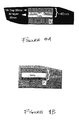
- FIG. 4A shows the predicted result at annealing temperature of 700° C. of a 20 nm layer silicon on a 20 nm layer of 80%Si/20%Ge, using 8 nm of cobalt;
- FIG. 4B shows this same layer of FIG. 4A at 800° C. annealing temperature
- FIG. 5 shows the measured electrical results and structural schematic of three different thickness layers of silicon, using 8 nm of cobalt.
- FIG. 1 A through FIG. 5 a preferred embodiment still now be described.
- the following discussion demonstrates the present invention as involving cobalt, there is no intent to confine the invention to this metal specifically. Nor is there intent to confine the present invention to the MOS structure exemplarily described herein.
- contact resistance can be improved is by lowering the Schottky barrier height between the silicide and source/drain (S/D) regions. Simulations suggest for TiSi 2 or CoSi 2 , that the contact resistance could be reduced by about a factor of 5-10 by lowering the barrier height from about 0.6 eV for conventional CoSi 2 /Si to about 0.3-0.5 eV for CoSi 2 in contact with SiGe, where the composition of the SiGe alloy ranges from 20%Ge to 100%Ge. As an example, this could result in a total parasitic resistance from silicide reducing from about a few hundred Ohm-micron to several tens of Ohm-micron for a device where total intrinsic resistance is less than 1000 Ohm-micron.
- silicide contact resistance could drop from almost 50% to less than 10% for a low barrier height contact.
- SiGe alloys in the S/D in CMOS devices has become increasingly attractive, such as for fabrication of strained silicon channel devices.
- SiGe S/D is now practical and manufacturable.
- silicide materials such as Co and Ti do not typically form single phase silicides when reacted with SiGe substrates, thereby resulting in precipitates and non uniform contacts.
- siliside should be directly on top of the SiGe without reacting with any of the SiGe S/D.
- silicide self-aligned silicide (self-aligned siliside is typically referred to as “salicide”) process which entails reaction of a blanket elemental metal such as Co or Ti with silicon in the S/D to form a metal silicide.
- the current invention forms a laterally and vertically self-aligned silicide contact to SiGe substrate by combining three key elements.
- FIGS. 1A through 1F A non-limiting exemplary technique of the present invention is first demonstrated in FIGS. 1A through 1F, followed by a discussion using the remaining figures to explain the rationale behind the technique and the details for selection of the parameters.
- FIG. 1A the CMOS devices 1 are shown as having been partially fabricated, for example, on an underlying SiGe layer 2 .
- this SiGe might be a layer on top of a silicon carrier wafer.
- the exemplary partial fabrication includes gate structures 3 and doped source/drain regions 4 .
- the gate structure 3 typically includes gate 3 A, which would typically be polysilicon or metal, and sidewall spacer 3 B, which would typically be SiO 2 or Si 3 N 4 .
- a silicon overlayer 5 is formed (e.g., grown) on the SiGe S/D regions, for example, by selective silicon epitaxy accomplished by commercial CVD equipment. This process allows controlled growth of a silicon layer 5 in the S/D regions.
- the gates 3 also receive the silicon layer 5 A.
- the S/D doping can be performed after selective silicon growth.
- the Si overlayer could be formed non-selectively on the SiGe layer before transistor gate formation.
- the silicon layer becomes substantially thinned, resulting in a much thinner Si overlayer on the SiGe S/D.
- the thickness of the Si is a key parameter of the present invention.
- a non-limiting, exemplary value for the Si layer thickness would be 20 nm, a value used in the result discussed later in FIGS. 4 and 5.
- a cobalt (Co) overlayer 6 is provided by conventional blanket deposition such as sputtering.
- the details of the deposition is not important since all metal will be selectively etched away that is not destined to become silicide in S/D regions 5 and, optionally, the gate regions 5 A. It is, however, preferable that the deposition result in planar coverage for these specific regions in order to provide a uniform thickness.
- the thickness of the cobalt layer is related to the thickness of the silicon layer. As an example, for a silicon layer with thickness 20 nm, a typical value of the cobalt layer thickness would be 8 nm. The derivation of this value will be explained later.
- the height of the sidewall 3 B be sufficient to prevent bridging between the gate 3 A and the S/D regions as raised in height by the additional silicon interlayer.
- a polysilicon gate is shown.
- the material for the gate is optionally metal.
- the composition of the gate may determine some of the details of implementing the present invention. That is, if metal is used and it is desired to preclude a silicide formation, then it would be obvious that the silicon regions 5 A should not be formed on the gate structures, or that prior to forming the silicon interlayer 5 , a passivation layer be applied over any exposed metal for which a silicide formation is not desired.
- the key that provides the vertical self-alignment feature of the present invention is a high temperature (i.e., 650-800° C.) annealing step that causes the cobalt layer 6 to interact selectively with only the silicon interlayer 5 (FIG. 1C) to form the desired structure in which a CoSi 2 layer directly contacts the underlying SiGe.
- the selected temperature is high enough to allow the formation of CoSi 2 using the silicon from the silicon interlayer 5 but not so high as to allow an interaction with the underlying SiGe layer 2 . This technique automatically solves the precipitation problem of the prior art.
- the inventors have discovered that, within a certain ratio of thicknesses for the cobalt and interlayer silicon layer and within a certain temperature range, it is possible to form a silicide using only the cobalt and silicon interlayer and that the underlying SiGe layer does not enter into the silicide formation unless the anneal temperature has exceeded an upper temperature threshold.
- This high temperature annealing could be done immediately following the cobalt layer deposition, but an optional additional lower temperature annealing has been found to possibly be useful to better ensure that the layer 6 of cobalt is removed from all areas except where the silicide formation is desired, i.e., the S/D regions 4 and (possibly) the gate contacts 3 A (see FIG. 1 A).
- the layer 6 of cobalt is removed from all areas except where the silicide formation is desired, i.e., the S/D regions 4 and (possibly) the gate contacts 3 A (see FIG. 1 A).
- cobalt be completely removed from the sidewalls 3 B so that no metal remains to cause shorts between the S/D regions 4 and the gate contacts 3 A.
- a lower temperature (e.g., approximately 500° C.) annealing results in a CoSi layer 7 over the silicon interlayer 5 of the S/D regions. Because of this difference in composition, the pure cobalt is then selectively etched away, leaving cobalt only in the form of the alloy CoSi in the desired regions 7 , as shown in FIG. 1 D. It is noted that an even lower temperature can be used for this low temperature anneal to result in Co 2 Si.
- the cobalt to be removed remains a pure metal, whereas the cobalt in regions to have silicide undergo a reaction so that the reacted cobalt phase (Co 2 Si or CoSi) is not etched away and can be further reacted subsequently to form CoSi 2 .
- etchants are well known in the art and may include, for example, H 2 O 2 :H 2 SO 4 in a ratio of 10:1, or the like.
- the low temperature annealing process may leave a portion of the silicon underlayer 5 . Any of such remaining residual silicon layer 5 will be converted into a CoSi 2 layer 8 , as shown in FIG. 1E by subsequently applying the higher-temperature annealing step mentioned earlier.
- the higher temperature annealing (e.g., approximately 650-800° C.) completes the silicide formation of any remaining silicon interlayer 5 to form the CoSi 2 layer 8 .
- the details of the higher-temperature annealing step would be obvious to one of ordinary skill in the art upon having read the description of the present invention.
- the higher temperature is achieved by simply ramping the temperature up rapidly, holding for several hundred seconds or less, and then rapidly ramping back down.
- FIG. 1F is a flowchart of the steps 1 . 1 - 1 . 6 corresponding to FIG. 1 A through FIG. 1 E.
- step 1 . 1 the CMOS gate structure has been formed on the SiGe layer, followed by the formation in step 1 . 2 of the raised S/D regions.
- step 1 . 3 the cobalt layer is deposited. If there is a low temperature annealing, it is done in step 1 . 4 , followed by the cobalt selective etch step 1 . 5 and concluded by the higher temperature annealing step 1 . 6 . If the low temperature annealing is not performed, the selective etching step 1 . 5 would follow the high temperature annealing step 1 . 6 .
- selective CVD silicide formation e.g., selective TiSi 2 CVD
- CVD selective TiSi 2 CVD
- previous work has shown that TiSi 2 can be deposited selectively directly on the S/D of a silicon CMOS device. Because the CVD process involves using precursor gases that contain silicon, in principle there is no need to consume silicon in the S/D area to form silicide, so that silicide can form with no net consumption of the S/D.
- FIG. 2 is shown an analysis of the CoSi 2 formation temperature as a function of Ge content in SiGe substrates for the case where Co is directly deposited on SiGe.
- the origin 20 represents SiGe at 0% Ge (i.e., pure silicon).
- the second point 21 represents 30% Ge (70% Si).
- the formation temperature increases by up to 150° C. or more for a Ge fraction approaching 30%.
- FIG. 3A shows the CoSi 2 formation temperature determined by x-ray diffraction for the case where Si interlayers are deposited on a Si 0.8 Ge 0.2 relaxed substrate before deposition of Co.
- An interesting feature is that for intermediate Si thickness, two CoSi 2 formation temperatures 31 , 32 are found. These temperatures signify the point at which the CoSi 2 x-ray signal is most rapidly increasing, indicating phase formation. Between the transitions, the CoSi 2 signal does not change significantly. Also, the separation of the transitions can be quite large, as much as 180° C. The inventors interpret this phenomenon in the following manner.
- the low temperature transition 31 represents the formation of CoSi 2 in the Si interlayer
- the high temperature transition 32 represents the formation of CoSi 2 in the underlying SiGe.
- little or no CoSi 2 formation takes place.
- the double transition only occurs when t CoSi2 >t Si >t CoSi , where t represents thickness. That is, the silicon thickness range where the silicon layer is thick enough to form pure CoSi from the fully reacted Co, but not thick enough to contain the CoSi 2 without reaction within the SiGe.
- the low temperature transition 31 is not the optional low-temperature annealing step 1 . 4 shown in FIG. 1F.
- a typical value for the optional low-temperature annealing step is 500° C., which is well below the low temperature transition 31 shown in FIG. 3 A.
- the low temperature transition 31 is the threshold temperature for the high temperature annealing step 1 . 6 , since according to the teaching of the present invention, this is the transition temperature at which the cobalt and the silicon interlayer form CoSi 2 .
- the high temperature transition 32 is an upper limit for the high temperature annealing step 1 . 6 , since according to the present invention, this transition 32 represents a temperature at which the underlying SiGe layer becomes involved in CoSi 2 formation, which condition is to be avoided to preclude precipitates at the SiGe interface.
- the above thickness relation may be represented as 3.66(t Co )>t Si >1.83(t Co ). It was initially proposed that in reaction of Co deposited directly on SiGe, the Ge that is extruded from the CoSi before CoSi 2 formation may reside at the interface between CoSi and the SiGe substrate and act as a diffusion barrier to CoSi 2 formation, which requires Si from the underlying SiGe. This was thought to be responsible for the delay in CoSi 2 formation on SiGe substrates.
- FIG. 1E the ideal structure of FIG. 1E can be realized by adhering to the following criteria:
- T ranges from about 650 C to 850 C or so. This ensures that the CoSi 2 bottom interface fully consumes the pure Si layer, but does extend into the SiGe layer, resulting in a planar interface substantially precipitate-free.
- the upper temperature, at which CoSi 2 begins to form in the SiGe layer will depend on the Ge fraction in the SiGe layer, and could be much higher than the example shown for 20% Ge composition.
- FIG. 3B perhaps better illustrates the significance of the above numbers for the present invention. Similar to FIG. 3A, this figure again plots on the vertical axis the CoSi 2 transition temperature for three thicknesses of cobalt (8 nm, 11 nm, 14 nm) for a layer of SiGe in the ratio of 80% Si to 20% Ge. In constrast to FIG. 3A, the horizontal axis is now based on the ratio of Si to Co thickness.
- FIG. 3B the low temperature CoSi 2 transition 31 and upper temperature CoSi 2 transition 32 are again visible. It should be noted that FIG. 3B shows that the upper transition 32 is a bit more variable than the lower transition 31 , when viewed as a function of the thickness of the cobalt layer. The significance of the thickness ratio of t Si /t Co becomes more visible in FIG. 3 B.
- the dual CoSi 2 formation temperatures 31 , 32 are found only in the intermediate ratios, that is, above the lower ratio threshold 33 (theoretically, where the ratio is 1.83) in which the silicon interlayer is entirely converted into CoSi and the upper threshold 34 (theoretically, a ratio of 3.66) in which the interlayer silicon has been entirely converted into CoSi 2 . Since the desired structure at the SiGe interface involves CoSi 2 rather than CoSi, it should be obvious that one would prefer a ratio above the lower threshold 33 , as was shown in FIG. 1 E.
- FIGS. 4A and 4B are illustrations of the expected results when applying the present invention.
- FIG. 4A shows the expected multilayer structure after annealing of a 20 nm TiN/8 nmCo/20 nm Si/20 nm Si20%Ge structure at 700° C.
- the 20 nm TiN layer is left on top to prevent oxidation and for clarity.
- a SEM micrograph of the actual sample clearly showed underneath the TiN layer a uniform layer of about 16-20 nm thickness.
- This layer represented the cobalt silicides and corresponded within measurement error to the initial 20 nm Si interlayer thickness.
- the silicide layer contained CoSi 2 at the bottom and CoSi at top, but the individual layers were not distinguished.
- the total thickness of the layers including TiN would be about 50 nm, clearly more than is observed. So it is concluded from the micrograph that full consumption of the silicon layer has taken place, but with no penetration of silicide into the SiGe substrate.
- FIG. 4B shows the expected result that, as the annealing temperature is increased to 800° C., the CoSi 2 will penetrate into the underlying SiGe. This situation was confirmed by an SEM micrograph.
- FIG. 5 shows the result of three thicknesses of silicon, 30 nm ( 50 ), 20 nm ( 51 ), and 12 nm( 52 ) using 8 nm cobalt.
- 8 nm Co thickness if the silicidation is indeed restricted to the 20 nm layer, it should produce about 9 nm CoSi 2 and 12 nm CoSi.
- FIG. 5 which shows that after 700 C annealing, the 20 nm Si sample ( 51 ) has a resistance which is intermediate between the case for pure CoSi ( 53 ) and pure CoSi 2 ( 54 ), indicating a mixture of CoSi 2 and CoSi.
- FIG. 5 also shows the resistance behavior for 8 nm Co deposited 12 nm ( 52 ) and 30 nm ( 50 ) Si interlayers layers with SiGe on the bottom.
- the 30 nm Si case has low resistance indicating full CoSi 2 formation (the Si thickness required to completely react 8 nm Co to CoSi 2 is about 29 nm).
- the 12 nm case indicates that a 700 C anneal leaves the resistance high, nearly the same as pure CoSi, indicating little or no CoSi 2 formation.
- the 20 nm measurement for 700° C. ( 55 ) and 800° C. ( 56 ) are the two samples shown in FIGS. 4A and 4B.
- the SEM measurement for the 12 nm Si interlayer ( 52 ) annealing at 700° C. ( 57 ) indicates that a layer is formed (not including the 20 nm TiN layer) whose total thickness is about 15-20 nm. This indicates that some of the SiGe substrate (3-8 nm) has been consumed during CoSi formation. Assuming this layer to include only cobalt monosilicide with dissolved Ge (Co ⁇ Si,Ge ⁇ 1 ), the expected thickness is about 17 nm, within the range observed in the SEM. Thus, in comparison to the FIG.
- the 12 nm Si layer ( 52 ) is not thick enough to form pure CoSi (tSi>15 nm), and silicidation is not prevented in the SiGe layer. This is because CoSi phase will dissolve Ge in its structure.
- FIG. 5 shows that the rough microstructure is reflected in a higher CoSi, resistance compared to the case where CoSi 2 is entirely contained in the Si layer.
- the 20 nm Si interlayer represents the ideal thickness in combination with 8 nm Co and 700 C annealing to obtain a CoSi 2 /SiGe planar interface with low contact resistance.
- the presence of the 12 nm CoSi on top of the CoSi 2 layer should not alter contact resistance to the SiGe substrate.
- the 25 Ohm/Sq sheet resistance seen in FIG. 5, though higher than normal will not impact series resistance significantly, because the series resistance is dominated by contact resistance.
- t Si can be chosen closer to 3.66 t Co .
- a couple of nanometers of silicide can be typically removed, resulting in substantial removal of the CoSi layer.
- the present invention provides a simple way to fabricate a low contact resistance device with CoSi 2 abutting a SiGe S/D formed by tailoring of selective Si interlayer thickness, Co thickness, and CoSi 2 annealing temperature.
- the structure is not limited in absolute thickness of the Si or Co layers, but allows a wide process window where the Si/Co ratio be between 1.83 and 3.66. For values somewhat less than 3.66, the presence of residual CoSi is not considered detrimental because the method ensures that the CoSi 2 layer forms directly on the SiGe providing a low contact resistance.
- the current invention provides a simple process to form a low resistance contact to a low band-gap SiGe device, providing lower resistance than conventional Si S/D CMOS where the band-gap is higher. It preserves the ability to use the conventional commercial laterally self-aligned silicide process (salicide) which is formed by reaction of a blanket metal with exposed S/D regions to form a silicide.
- silicide conventional commercial laterally self-aligned silicide process
- the present invention overcomes the problem of reaction of metal with SiGe, which forms undesirable multiphase microstructure, by using a sacrificial Si overlayer within which to form the silicide. It ensures that a vertically self-aligned silicide process occurs which places the bottom silicide interface at the top of the original SiGe/Si interface, by taking advantage of the difference in silicide reaction temperatures.
- the present invention allows for a large process window in terms of annealing temperature to form CoSi 2 .
- CMOS complementary metal-oxide-semiconductor
- MODFET modulation doped field effect transistors
- strained silicon channel CMOS strained silicon channel CMOS
- silicon-on-insulator devices containing SiGe silicon-on-insulator devices containing SiGe.
Landscapes
- Electrodes Of Semiconductors (AREA)
- Insulated Gate Type Field-Effect Transistor (AREA)
Abstract
Description
Claims (3)
Priority Applications (2)
| Application Number | Priority Date | Filing Date | Title |
|---|---|---|---|
| US10/156,782 US6690072B2 (en) | 2002-05-24 | 2002-05-24 | Method and structure for ultra-low contact resistance CMOS formed by vertically self-aligned COSI2 on raised source drain Si/SiGe device |
| US10/419,888 US6972250B2 (en) | 2002-05-24 | 2003-04-22 | Method and structure for ultra-low contact resistance CMOS formed by vertically self-aligned CoSi2 on raised source drain Si/SiGe device |
Applications Claiming Priority (1)
| Application Number | Priority Date | Filing Date | Title |
|---|---|---|---|
| US10/156,782 US6690072B2 (en) | 2002-05-24 | 2002-05-24 | Method and structure for ultra-low contact resistance CMOS formed by vertically self-aligned COSI2 on raised source drain Si/SiGe device |
Related Child Applications (1)
| Application Number | Title | Priority Date | Filing Date |
|---|---|---|---|
| US10/419,888 Division US6972250B2 (en) | 2002-05-24 | 2003-04-22 | Method and structure for ultra-low contact resistance CMOS formed by vertically self-aligned CoSi2 on raised source drain Si/SiGe device |
Publications (2)
| Publication Number | Publication Date |
|---|---|
| US20030219965A1 US20030219965A1 (en) | 2003-11-27 |
| US6690072B2 true US6690072B2 (en) | 2004-02-10 |
Family
ID=29549229
Family Applications (2)
| Application Number | Title | Priority Date | Filing Date |
|---|---|---|---|
| US10/156,782 Expired - Lifetime US6690072B2 (en) | 2002-05-24 | 2002-05-24 | Method and structure for ultra-low contact resistance CMOS formed by vertically self-aligned COSI2 on raised source drain Si/SiGe device |
| US10/419,888 Expired - Fee Related US6972250B2 (en) | 2002-05-24 | 2003-04-22 | Method and structure for ultra-low contact resistance CMOS formed by vertically self-aligned CoSi2 on raised source drain Si/SiGe device |
Family Applications After (1)
| Application Number | Title | Priority Date | Filing Date |
|---|---|---|---|
| US10/419,888 Expired - Fee Related US6972250B2 (en) | 2002-05-24 | 2003-04-22 | Method and structure for ultra-low contact resistance CMOS formed by vertically self-aligned CoSi2 on raised source drain Si/SiGe device |
Country Status (1)
| Country | Link |
|---|---|
| US (2) | US6690072B2 (en) |
Cited By (9)
| Publication number | Priority date | Publication date | Assignee | Title |
|---|---|---|---|---|
| US20050090082A1 (en) * | 2003-10-28 | 2005-04-28 | Texas Instruments Incorporated | Method and system for improving performance of MOSFETs |
| US20060094249A1 (en) * | 2004-10-29 | 2006-05-04 | Demkov Alexander A | Semiconductor structure having a metallic buffer layer and method for forming |
| US20060207629A1 (en) * | 2004-12-16 | 2006-09-21 | Sematech, Inc. | Method and apparatus for an in-situ ultraviolet cleaning tool |
| US20090008623A1 (en) * | 2007-07-03 | 2009-01-08 | Samsung Electronics Co., Ltd. | Methods of fabricating nonvolatile memory device and a nonvolatile memory device |
| US8445334B1 (en) | 2011-12-20 | 2013-05-21 | International Business Machines Corporation | SOI FinFET with recessed merged Fins and liner for enhanced stress coupling |
| US8455313B1 (en) | 2011-12-27 | 2013-06-04 | International Business Machines Corporation | Method for fabricating finFET with merged fins and vertical silicide |
| US8871626B2 (en) | 2011-12-20 | 2014-10-28 | International Business Machines Corporation | FinFET with vertical silicide structure |
| US8877604B2 (en) | 2012-12-17 | 2014-11-04 | International Business Machines Corporation | Device structure with increased contact area and reduced gate capacitance |
| EP4572558A1 (en) * | 2023-12-12 | 2025-06-18 | SwaySure Technology Co., Ltd. | Pmos transistor and method of preparing pmos transistor, cmos circuit and method of preparing cmos circuit |
Families Citing this family (24)
| Publication number | Priority date | Publication date | Assignee | Title |
|---|---|---|---|---|
| US6833556B2 (en) | 2002-08-12 | 2004-12-21 | Acorn Technologies, Inc. | Insulated gate field effect transistor having passivated schottky barriers to the channel |
| US7084423B2 (en) | 2002-08-12 | 2006-08-01 | Acorn Technologies, Inc. | Method for depinning the Fermi level of a semiconductor at an electrical junction and devices incorporating such junctions |
| US6905976B2 (en) * | 2003-05-06 | 2005-06-14 | International Business Machines Corporation | Structure and method of forming a notched gate field effect transistor |
| US9673280B2 (en) * | 2003-06-12 | 2017-06-06 | Taiwan Semiconductor Manufacturing Company, Ltd. | Cobalt silicidation process for substrates comprised with a silicon-germanium layer |
| DE10358721B3 (en) * | 2003-12-15 | 2005-09-08 | Infineon Technologies Ag | Method of manufacturing cobalt silicide contacts on semiconductor material in contact holes where the cobalt in the silicon form an alloy esp. for a field of memory cells |
| US6881635B1 (en) | 2004-03-23 | 2005-04-19 | International Business Machines Corporation | Strained silicon NMOS devices with embedded source/drain |
| US7098114B1 (en) * | 2004-06-22 | 2006-08-29 | Integrated Device Technology, Inc. | Method for forming cmos device with self-aligned contacts and region formed using salicide process |
| CN100517609C (en) * | 2004-09-09 | 2009-07-22 | 国际商业机器公司 | Method for making silicide on the surface of SiGe-containing substrate |
| US7732289B2 (en) * | 2005-07-05 | 2010-06-08 | Taiwan Semiconductor Manufacturing Company, Ltd. | Method of forming a MOS device with an additional layer |
| TW200725707A (en) * | 2005-12-30 | 2007-07-01 | Ind Tech Res Inst | Method for forming titanium silicide upon a semiconductor device with lower source/drain sheet resistance |
| US7485572B2 (en) * | 2006-09-25 | 2009-02-03 | International Business Machines Corporation | Method for improved formation of cobalt silicide contacts in semiconductor devices |
| US7566651B2 (en) | 2007-03-28 | 2009-07-28 | International Business Machines Corporation | Low contact resistance metal contact |
| US20090050975A1 (en) * | 2007-08-21 | 2009-02-26 | Andres Bryant | Active Silicon Interconnect in Merged Finfet Process |
| US8207064B2 (en) * | 2009-09-17 | 2012-06-26 | Sandisk 3D Llc | 3D polysilicon diode with low contact resistance and method for forming same |
| US8557693B2 (en) | 2010-06-03 | 2013-10-15 | International Business Machines Corporation | Contact resistivity reduction in transistor devices by deep level impurity formation |
| US9006801B2 (en) | 2011-01-25 | 2015-04-14 | International Business Machines Corporation | Method for forming metal semiconductor alloys in contact holes and trenches |
| US20120231591A1 (en) * | 2011-03-11 | 2012-09-13 | Globalfoundries Inc. | Methods for fabricating cmos integrated circuits having metal silicide contacts |
| US9087741B2 (en) | 2011-07-11 | 2015-07-21 | International Business Machines Corporation | CMOS with dual raised source and drain for NMOS and PMOS |
| CN103137475B (en) * | 2011-11-23 | 2015-09-16 | 中国科学院微电子研究所 | A kind of semiconductor structure and its manufacturing method |
| KR20140121617A (en) * | 2013-04-08 | 2014-10-16 | 삼성전자주식회사 | Semiconductor devices and methods of manufacturing the same |
| US9496149B2 (en) * | 2014-04-14 | 2016-11-15 | Taiwan Semiconductor Manufacturing Company, Ltd. | Semiconductor devices and methods for manufacturing the same |
| US9620611B1 (en) | 2016-06-17 | 2017-04-11 | Acorn Technology, Inc. | MIS contact structure with metal oxide conductor |
| DE112017005855T5 (en) | 2016-11-18 | 2019-08-01 | Acorn Technologies, Inc. | Nanowire transistor with source and drain induced by electrical contacts with negative Schottky barrier height |
| US12154854B2 (en) * | 2022-01-07 | 2024-11-26 | Globalfoundries Singapore Pte. Ltd. | Electronic fuses with a silicide layer having multiple thicknesses |
Citations (6)
| Publication number | Priority date | Publication date | Assignee | Title |
|---|---|---|---|---|
| US5818100A (en) * | 1995-01-18 | 1998-10-06 | Lsi Logic Corporation | Product resulting from selective deposition of polysilicon over single crystal silicon substrate |
| US5818092A (en) * | 1996-02-15 | 1998-10-06 | Intel Corporation | Polycide film |
| US5955745A (en) * | 1995-09-29 | 1999-09-21 | Nec Corporation | Semiconductor device having SiGe spacer under an active layer |
| US6214679B1 (en) * | 1999-12-30 | 2001-04-10 | Intel Corporation | Cobalt salicidation method on a silicon germanium film |
| US6235568B1 (en) * | 1999-01-22 | 2001-05-22 | Intel Corporation | Semiconductor device having deposited silicon regions and a method of fabrication |
| US6518155B1 (en) * | 1997-06-30 | 2003-02-11 | Intel Corporation | Device structure and method for reducing silicide encroachment |
Family Cites Families (1)
| Publication number | Priority date | Publication date | Assignee | Title |
|---|---|---|---|---|
| US4818100A (en) * | 1987-09-30 | 1989-04-04 | Eaton Corporation | Laser doppler and time of flight range measurement |
-
2002
- 2002-05-24 US US10/156,782 patent/US6690072B2/en not_active Expired - Lifetime
-
2003
- 2003-04-22 US US10/419,888 patent/US6972250B2/en not_active Expired - Fee Related
Patent Citations (6)
| Publication number | Priority date | Publication date | Assignee | Title |
|---|---|---|---|---|
| US5818100A (en) * | 1995-01-18 | 1998-10-06 | Lsi Logic Corporation | Product resulting from selective deposition of polysilicon over single crystal silicon substrate |
| US5955745A (en) * | 1995-09-29 | 1999-09-21 | Nec Corporation | Semiconductor device having SiGe spacer under an active layer |
| US5818092A (en) * | 1996-02-15 | 1998-10-06 | Intel Corporation | Polycide film |
| US6518155B1 (en) * | 1997-06-30 | 2003-02-11 | Intel Corporation | Device structure and method for reducing silicide encroachment |
| US6235568B1 (en) * | 1999-01-22 | 2001-05-22 | Intel Corporation | Semiconductor device having deposited silicon regions and a method of fabrication |
| US6214679B1 (en) * | 1999-12-30 | 2001-04-10 | Intel Corporation | Cobalt salicidation method on a silicon germanium film |
Cited By (16)
| Publication number | Priority date | Publication date | Assignee | Title |
|---|---|---|---|---|
| US20050090082A1 (en) * | 2003-10-28 | 2005-04-28 | Texas Instruments Incorporated | Method and system for improving performance of MOSFETs |
| US20060094249A1 (en) * | 2004-10-29 | 2006-05-04 | Demkov Alexander A | Semiconductor structure having a metallic buffer layer and method for forming |
| US7365410B2 (en) | 2004-10-29 | 2008-04-29 | Freescale, Semiconductor, Inc. | Semiconductor structure having a metallic buffer layer and method for forming |
| US20060207629A1 (en) * | 2004-12-16 | 2006-09-21 | Sematech, Inc. | Method and apparatus for an in-situ ultraviolet cleaning tool |
| US7921859B2 (en) | 2004-12-16 | 2011-04-12 | Sematech, Inc. | Method and apparatus for an in-situ ultraviolet cleaning tool |
| US20110132394A1 (en) * | 2004-12-16 | 2011-06-09 | Abbas Rastegar | Method and Apparatus for an In-Situ Ultraviolet Cleaning Tool |
| US8206510B2 (en) | 2004-12-16 | 2012-06-26 | Sematech, Inc. | Method and apparatus for an in-situ ultraviolet cleaning tool |
| US20090008623A1 (en) * | 2007-07-03 | 2009-01-08 | Samsung Electronics Co., Ltd. | Methods of fabricating nonvolatile memory device and a nonvolatile memory device |
| US8445334B1 (en) | 2011-12-20 | 2013-05-21 | International Business Machines Corporation | SOI FinFET with recessed merged Fins and liner for enhanced stress coupling |
| US8723262B2 (en) | 2011-12-20 | 2014-05-13 | International Business Machines Corporation | SOI FinFET with recessed merged fins and liner for enhanced stress coupling |
| US8871626B2 (en) | 2011-12-20 | 2014-10-28 | International Business Machines Corporation | FinFET with vertical silicide structure |
| US8455313B1 (en) | 2011-12-27 | 2013-06-04 | International Business Machines Corporation | Method for fabricating finFET with merged fins and vertical silicide |
| US8637931B2 (en) | 2011-12-27 | 2014-01-28 | International Business Machines Corporation | finFET with merged fins and vertical silicide |
| US8877604B2 (en) | 2012-12-17 | 2014-11-04 | International Business Machines Corporation | Device structure with increased contact area and reduced gate capacitance |
| US9385231B2 (en) | 2012-12-17 | 2016-07-05 | Globalfoundries Inc. | Device structure with increased contact area and reduced gate capacitance |
| EP4572558A1 (en) * | 2023-12-12 | 2025-06-18 | SwaySure Technology Co., Ltd. | Pmos transistor and method of preparing pmos transistor, cmos circuit and method of preparing cmos circuit |
Also Published As
| Publication number | Publication date |
|---|---|
| US20030219971A1 (en) | 2003-11-27 |
| US20030219965A1 (en) | 2003-11-27 |
| US6972250B2 (en) | 2005-12-06 |
Similar Documents
| Publication | Publication Date | Title |
|---|---|---|
| US6690072B2 (en) | Method and structure for ultra-low contact resistance CMOS formed by vertically self-aligned COSI2 on raised source drain Si/SiGe device | |
| US6987050B2 (en) | Self-aligned silicide (salicide) process for low resistivity contacts to thin film silicon-on-insulator and bulk MOSFETS and for shallow junctions | |
| JP2586345B2 (en) | Semiconductor device comprising cobalt silicide film and method of manufacturing the device | |
| US7396767B2 (en) | Semiconductor structure including silicide regions and method of making same | |
| EP0501561B1 (en) | Method of manufacturing a semiconductor device whereby a self-aligned cobalt or nickel silicide is formed | |
| US5217923A (en) | Method of fabricating a semiconductor device having silicided source/drain regions | |
| JP3217015B2 (en) | Method for forming field effect transistor | |
| US20070128867A1 (en) | Method for enhanced uni-directional diffusion of metal and subsequent silicide formation | |
| US7015126B2 (en) | Method of forming silicided gate structure | |
| US6905560B2 (en) | Retarding agglomeration of Ni monosilicide using Ni alloys | |
| US20030068883A1 (en) | Self-aligned silicide (salicide) process for strained silicon MOSFET on SiGe and structure formed thereby | |
| US6323130B1 (en) | Method for self-aligned formation of silicide contacts using metal silicon alloys for limited silicon consumption and for reduction of bridging | |
| US5449642A (en) | Method of forming metal-disilicide layers and contacts | |
| US6329277B1 (en) | Method of forming cobalt silicide | |
| Kittl et al. | Silicides and germanides for nano-CMOS applications | |
| US7786578B2 (en) | Eliminating metal-rich silicides using an amorphous Ni alloy silicide structure | |
| JP2000223713A (en) | Semiconductor element and its manufacture | |
| US7105439B2 (en) | Cobalt/nickel bi-layer silicide process for very narrow line polysilicon gate technology | |
| JP2002184717A (en) | Semiconductor device and manufacturing method thereof | |
| US20070020929A1 (en) | Method for reducing dendrite formation in nickel silicon salicide processes | |
| Roy et al. | The future of silicide for CMOS contacts | |
| JPH04260325A (en) | Manufacture of semiconductor device | |
| JPH1012570A (en) | Method for manufacturing semiconductor device | |
| Zaima et al. | Silicide and germanide technology for interconnections in ultra-large-scale integrated (ULSI) applications | |
| US20050227469A1 (en) | Method of manufacturing semiconductor device |
Legal Events
| Date | Code | Title | Description |
|---|---|---|---|
| AS | Assignment |
Owner name: INTERNATIONAL BUSINESS MACHINES CORPORATION, NEW Y Free format text: ASSIGNMENT OF ASSIGNORS INTEREST;ASSIGNORS:CABRAL JR., CYRIL;CARRUTHERS, ROY A.;CHAN, KEVIN K.;AND OTHERS;REEL/FRAME:012961/0043;SIGNING DATES FROM 20020517 TO 20020520 |
|
| STCF | Information on status: patent grant |
Free format text: PATENTED CASE |
|
| FEPP | Fee payment procedure |
Free format text: PAYOR NUMBER ASSIGNED (ORIGINAL EVENT CODE: ASPN); ENTITY STATUS OF PATENT OWNER: LARGE ENTITY |
|
| CC | Certificate of correction | ||
| FPAY | Fee payment |
Year of fee payment: 4 |
|
| FPAY | Fee payment |
Year of fee payment: 8 |
|
| FPAY | Fee payment |
Year of fee payment: 12 |
|
| AS | Assignment |
Owner name: GLOBALFOUNDRIES U.S. 2 LLC, NEW YORK Free format text: ASSIGNMENT OF ASSIGNORS INTEREST;ASSIGNOR:INTERNATIONAL BUSINESS MACHINES CORPORATION;REEL/FRAME:036550/0001 Effective date: 20150629 |
|
| AS | Assignment |
Owner name: GLOBALFOUNDRIES INC., CAYMAN ISLANDS Free format text: ASSIGNMENT OF ASSIGNORS INTEREST;ASSIGNORS:GLOBALFOUNDRIES U.S. 2 LLC;GLOBALFOUNDRIES U.S. INC.;REEL/FRAME:036779/0001 Effective date: 20150910 |
|
| AS | Assignment |
Owner name: AURIGA INNOVATIONS, INC., CANADA Free format text: ASSIGNMENT OF ASSIGNORS INTEREST;ASSIGNOR:GLOBALFOUNDRIES INC.;REEL/FRAME:041741/0358 Effective date: 20161207 |