US6684800B2 - Personal watercraft - Google Patents
Personal watercraft Download PDFInfo
- Publication number
- US6684800B2 US6684800B2 US10/215,283 US21528302A US6684800B2 US 6684800 B2 US6684800 B2 US 6684800B2 US 21528302 A US21528302 A US 21528302A US 6684800 B2 US6684800 B2 US 6684800B2
- Authority
- US
- United States
- Prior art keywords
- fuel
- water separator
- container
- opening
- water
- Prior art date
- Legal status (The legal status is an assumption and is not a legal conclusion. Google has not performed a legal analysis and makes no representation as to the accuracy of the status listed.)
- Expired - Fee Related
Links
Images


Classifications
-
- B—PERFORMING OPERATIONS; TRANSPORTING
- B63—SHIPS OR OTHER WATERBORNE VESSELS; RELATED EQUIPMENT
- B63B—SHIPS OR OTHER WATERBORNE VESSELS; EQUIPMENT FOR SHIPPING
- B63B17/00—Vessels parts, details, or accessories, not otherwise provided for
- B63B17/06—Refuse discharge, e.g. for ash
-
- B—PERFORMING OPERATIONS; TRANSPORTING
- B63—SHIPS OR OTHER WATERBORNE VESSELS; RELATED EQUIPMENT
- B63B—SHIPS OR OTHER WATERBORNE VESSELS; EQUIPMENT FOR SHIPPING
- B63B17/00—Vessels parts, details, or accessories, not otherwise provided for
- B63B17/0027—Tanks for fuel or the like ; Accessories therefor, e.g. tank filler caps
-
- B—PERFORMING OPERATIONS; TRANSPORTING
- B63—SHIPS OR OTHER WATERBORNE VESSELS; RELATED EQUIPMENT
- B63B—SHIPS OR OTHER WATERBORNE VESSELS; EQUIPMENT FOR SHIPPING
- B63B34/00—Vessels specially adapted for water sports or leisure; Body-supporting devices specially adapted for water sports or leisure
- B63B34/10—Power-driven personal watercraft, e.g. water scooters; Accessories therefor
-
- B—PERFORMING OPERATIONS; TRANSPORTING
- B63—SHIPS OR OTHER WATERBORNE VESSELS; RELATED EQUIPMENT
- B63H—MARINE PROPULSION OR STEERING
- B63H21/00—Use of propulsion power plant or units on vessels
- B63H21/38—Apparatus or methods specially adapted for use on marine vessels, for handling power plant or unit liquids, e.g. lubricants, coolants, fuels or the like
Definitions
- the present invention relates to a personal watercraft (PWC) which ejects water rearward and planes on a water surface as the resulting reaction, and more particularly to a personal watercraft having a system of separating and eliminating water contained in fuel from the fuel.
- PWC personal watercraft
- the personal watercraft has a straddle-type body structure, and is configured to have a water jet pump that pressurizes and accelerates water sucked from a water intake generally provided on a hull bottom surface and ejects it rearward from an outlet port. Thereby, the personal watercraft is propelled.
- the personal watercraft is equipped with an engine as a power source for driving the water jet pump, a fuel tank for reserving fuel (gasoline) supplied to the engine, and the like, inside of an outer shell of the body.
- the fuel is commonly fed into the fuel tank at the waterside or on the water. Therefore, water ingress into the fuel tank is sometimes caused by water splashes to the fuel tank during fuel feeding.
- the fuel containing water is supplied to the engine, engine power efficiency is reduced.
- the fuel tank is made of semi-transparent resin so that the inside thereof is visible from outside. Inside the fuel tank, the water tends to move downwardly to the bottom because of its specific gravity higher than the specific gravity of the fuel. The water in the fuel tank is detected by visual inspection from outside. After being detected, the water is discharged, together with the fuel, from the fuel tank.
- the present invention address the above-described condition, and an object of the present invention is to provide a personal watercraft capable of separating and eliminating water contained in fuel without inspecting whether or not the water is present in a fuel tank.
- a personal watercraft comprising: an internal combustion engine; a fuel tank for reserving fuel supplied to the internal combustion engine; an air-fuel mixture generating means for mixing the fuel from the fuel tank with air to generate air-fuel mixture; a fuel supply passage connecting the fuel tank to the air-fuel mixture generating means; and a water separator provided in the fuel supply passage.
- the water contained in the fuel in the fuel tank can be separated and eliminated from the fuel by using the water separator.
- the fuel nearly free from water can be supplied to the internal combustion engine, and consequently, a power efficiency of the internal combustion engine is not reduced.
- the elimination of water is accomplished merely by discharging the separated water from the water separator, without regularly inspecting whether or not the water is present in the fuel tank. In addition, it is not necessary to discharge the fuel from the fuel tank when the fuel contains the water.
- the personal watercraft may further comprise a body member to which the water separator is removably mounted, and the water separator may comprise a container for reserving the fuel and a cap member removably attached to the container, for covering an opening in the container.
- the personal watercraft may further comprise: a cover member, the cover member being adapted to cover a portion where the water separator is mounted and expose the portion where the water separator is mounted. Since the cover member can cover the portion where the water separator is mounted, the body's external appearance is visually favorable.
- the cap member when the cover member covers the portion where the water separator is mounted, the cap member may be in contact with a inner face of the cover member or in close proximity to the inner face of the cover member with a slight gap.
- the personal watercraft may further comprise: a body member provided with an opening capable of being covered and uncovered, and the water separator may be removably mounted inside of the body member in the vicinity of the opening, and the water separator may comprise a container for reserving the fuel and a cap member removably attached to the container, for covering an opening in the container.
- the rider can easily make access to the water separator by uncovering the opening, and then remove the water separator from the body and remove the cap member from the container. In this manner, the water in the water separator can be discharged.
- the personal watercraft may further comprise: a discharge passage; and an opening/closing means for opening/closing the discharge passage, and the water separator may have a container for reserving the fuel, and the discharge passage may be provided at a bottom of the container.
- the personal watercraft may further comprise: a biasing means for biasing the opening/closing means to be at a closed position; and an operating means for opening the opening/closing means against a biasing force of the biasing means.
- FIG. 1 is a side view showing a personal watercraft according to a first embodiment of the present invention
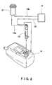
- FIG. 2 is a view of a fuel supply system of the personal watercraft in FIG. 1;
- FIG. 3 is a side view of the personal watercraft in FIG. 1, with a hatch cover being at an open position;
- FIG. 4 is a longitudinal sectional view of a water separator
- FIG. 5 is a plan view of the personal watercraft in FIG. 1, with a seat, a hatch cover, a box cover, and the like omitted;
- FIG. 6 is a longitudinal sectional view of a water separator of a personal watercraft according to a second embodiment of the present invention.
- FIG. 7 is a perspective view showing that a branched member supports the water separator.
- FIG. 8 is a rear view of the personal watercraft in FIG. 6 .
- FIG. 1 is a side view of a personal watercraft 1 according to a first embodiment of the present invention.
- the personal watercraft 1 has a FRP body.
- the body is mainly comprised of a hull 2 and a deck 3 covering the hull 2 from above.
- the hull 2 and the deck 3 are body members.
- An engine (internal combustion engine) 4 as a power source is equipped inside of the body comprised of the hull 2 and the deck 3 .
- the rotation of the engine 4 is transmitted to an impeller 5 through a drive shaft.
- the impeller 5 and a casing 6 enclosing outer periphery of the impeller 5 constitute a water jet pump 7 .
- An opening is provided as a water intake 8 in a bottom surface of the hull 2 .
- the water is sucked from the water intake 8 and fed to the water jet pump 7 .
- the water jet pump 7 pressurizes and accelerates the water.
- the pressurized and accelerated water is discharged through a pump nozzle behind the water jet pump 7 , thereby propelling the personal watercraft 1 .
- the pump nozzle is covered with a steering nozzle 9 provided behind the pump nozzle.
- reference numeral 10 denotes a reverse deflector.
- the deflector 10 is swung downward to a lower position around a horizontally mounted swinging shaft to deflect the ejected water from the steering nozzle 9 forward, and as the resulting reaction, the personal watercraft 1 moves rearward.
- a straddle-type seat 11 is mounted at the center portion of the deck 3 .
- a steering handle 12 is provided in front of the seat 11 .
- the steering nozzle 9 is swung toward the opposite direction so that the watercraft 1 can be correspondingly turned to a desired direction.
- a hatch cover 13 is mounted in front of the handle 12 so as to partially cover the deck 3 .
- a box cover 58 is mounted behind the handle 12 so as to cover an accommodating portion 59 provided in the deck 3 .
- the seat 11 is removable from the deck 3 .
- the seat 11 is mounted on the deck 3 .
- the seat 11 is removed from the deck 3 .
- an opening formed in the deck 3 is exposed, and maintenance works or the like of the internal combustion engine or the like can be carried out through the opening.
- the hatch cover 13 is openable/closable as indicated by an arrow 3 in FIG. 1 .
- the hatch cover 13 is pivotally attached to the deck 3 around its tip end as a pivot axis. By opening the hatch cover 13 , an opening formed in the deck 3 is exposed. The inner space of the opening is utilized for accommodating equipment and the like.
- the box cover 58 is openably attached to the deck 3 . By opening the box cover 58 , the accommodating portion 59 is exposed.
- a fuel tank 14 made of resin is provided inside of the body comprised of the hull 2 and the deck 3 .
- the role of the fuel tank 14 is to reserve the fuel to be supplied to the engine 4 .
- FIG. 2 is a schematic view of a fuel supply system installed in the personal watercraft 1 .
- a fuel pump 15 is mounted to the fuel tank 14 .
- the fuel reserved in the fuel tank 14 is pumped into an air-fuel mixture generating means 17 by a fuel pump 15 through a fuel supply passage.
- the “air-fuel mixture generating means” refers to a means for mixing air with fuel to generate air-fuel mixture.
- a carburetor, a fuel injector, or the like corresponds to the “air-fuel mixture generating means.”
- the excess fuel which has not been supplied into a combustion chamber of the engine 4 is returned into the fuel tank 14 through a return pipe 18 .
- a water separator 21 is provided in the fuel supply passage connecting the fuel pump 15 to the air-fuel mixture generating means 17 , for the purpose of separating water contained in the fuel.
- the fuel from the fuel pump 15 is led to the water separator 21 through a pipe 16 a and then to the air-fuel mixture generating means 17 through a pipe 16 b .
- the water separator 21 serves to separate the water from the fuel by specific gravity difference between the fuel and the water.
- FIG. 3 is a side view of the personal watercraft 1 with the hatch cover 13 being at an open position.
- the water separator 21 is mounted to the deck 3 .
- a portion of the deck 3 where the water separator 21 is mounted is covered with the hatch cover 13 by closing hatch cover 13 , and uncovered by opening the hatch cover 13 .
- the hatch cover 13 functions as a cover member provided over the water separator 21 .
- FIG. 4 is a longitudinal sectional view of the water separator 21 .
- FIG. 4 shows a structure of the water separator 21 and a structure of mounting of the water separator 21 to the deck 3 .
- the water separator 21 is mainly comprised of a substantially cylindrical container 22 and the cap member 25 .
- the container 22 has a required volume and its upper end is opened.
- the container 22 is made of semi-transparent resin.
- the cap member 25 covers the opening in the upper end of the container 25 .
- the water separator 21 is mounted to the deck 3 .
- a tubular support member 27 is secured to the deck 3 by means of a bolt 51 and a nut 52 such that the member 27 penetrates the deck 3 through a circular hole portion formed in the deck 3 .
- the outer diameter of the container 22 is slightly smaller than the inner diameter of the support member 27 .
- the water separator 21 is mounted so as to extend along the inner inside of the support member 27 .
- a flange 22 a outwardly extends in a radial direction at the upper end of the container 22 . Because the outer diameter of the flange 22 a is larger than the inner diameter of the support member 27 , the container 22 is supported by the support member 27 .
- the cap member 25 is screwed to the support member 27 .
- a female screw is formed on an inner peripheral face of the cap member 25 and a male screw is formed on an outer peripheral face of the support member 27 in the vicinity of the upper end.
- the female screw of the cap member 25 and the male screw of the support member 27 are threadedly engaged.
- the flange 22 a is securely retained between the cap member 25 and the support member 27 to allow the container 22 to be secured to the deck 3 .
- a gasket 26 is provided between the support member 27 and the flange 22 a and a gasket 28 is provided between the cap member 25 and the flange 22 a . In this manner, the opening in the upper end of the container 22 is covered with the cap member 25 .
- the hatch cover 13 covers the cap member 25 from above.
- the hatch cover 13 is in contact with or in close proximity to the cap member 25 . In other words, there is no or slight gap between the upper face of the cap member 25 and the rear face of the hatch cover 13 .
- the container 22 is provided with a fuel inflow pipe 23 and a fuel outflow pipe 24 .
- the fuel inflow pipe 23 serves to lead the fuel from the outside of the container 22 to the inside thereof and is connected to the pipe 16 a .
- the fuel inflow pipe 23 has an opening 23 a inside of the container 22 at a position spaced a predetermined distance above the bottom.
- the fuel outflow pipe 24 serves to lead the fuel from the inside of the container 22 to the outside thereof and is connected to the pipe 16 b .
- the fuel outflow pipe 24 has an opening 24 a inside of the container 22 at a position higher than the position of the opening 23 a of the fuel inflow pipe 23 .
- the fuel in the fuel tank 14 is pumped into the container 22 by the fuel pump 15 through the pipe 16 a and the fuel inflow pipe 23 .
- the fuel containing water flows into the container 22 , the water is spontaneously separated from the fuel in the container 22 due to specific gravity difference between the water and the fuel and moves downwardly to the bottom of the container 22 .
- W denotes the water collected in the bottom of the container 22 and F denotes the fuel overlying the water.
- the fuel, from which the water has been separated in the water separator 21 flows from the opening 24 a of the fuel outflow pipe 24 into the fuel outflow pipe 24 . Then, the fuel is led to the outside of the container 22 through the fuel outflow pipe 24 . Further, the fuel is led to the air-fuel mixture generating means 17 through the pipe 16 b.
- the water separator 21 is provided in the fuel supply passage connecting the fuel tank 14 to the air-fuel mixture generating means 17 , for the purpose of separating the water contained in the fuel. Therefore, the fuel nearly free from water can be supplied to the engine 4 . Consequently, a power efficiency of the engine 4 is not reduced.
- the water in the water separator 21 can be detected by regular visual inspection, or otherwise by using a water sensor provided in the water separator 21 . Since the water separator 21 is removably mounted to the deck 3 , the water separator 21 can be removed from the deck 3 and then the water is discharged from the water separator 21 . When removing the water separator 21 from the deck 3 , first of all, the hatch cover 13 is opened, thereby exposing the portion of the deck 3 where the water separator 21 is mounted. Following this, the cap member 25 screwed to the support member 27 is detached from the support member 27 .
- the container 22 supported by the support member 27 is lifted up from the support member 27 , with the pipes 16 a , 16 b being connected to the container 22 . Then, the container 22 is tilted or inverted, thereby discharging the water in the container 22 with the fuel. It should be appreciated that the container 22 is preferably kept away from the body of the watercraft 1 during the discharge of the water and the fuel in order to prevent the body, for example, the deck 3 , from being contaminated.
- the water separator 21 is re-mounted to the deck 3 in the reverse order of that for removing the water separator 21 from the deck 3 .
- the hatch cover 13 When re-mounting the water separator 21 to the deck 3 , the hatch cover 13 can be fully closed in the state in which the cap member 25 is firmly fastened to the support member 27 . Conversely, when the cap member 25 is not firmly fastened to the support member 27 , the hatch cover 13 is incompletely closed. This is because the hatch cover 13 is placed so as to be in contact with or in close proximity to the cap member 25 in the state in which the cap member 25 is firmly fastened to the support member 27 . Therefore, the user finds that the cap member 25 is not firmly fastened to the support member 27 when the hatch cover 13 is incompletely closed.
- the water separator 21 is mounted to the portion of the deck 3 which is exposed by opening the hatch cover 13 .
- the portion of the deck 3 where the water separator 21 should be mounted is not intended to be limited to the portion covered with the hatch cover 13 .
- the water separator 21 may be mounted to the portion of the deck 3 which is exposed by removing the seat 11 .
- the portion of the deck 3 which is beneath the seat 11 is covered with the seat 11 in the state in which the seat 11 is mounted on the deck 3 and is exposed by removing the seat 11 .
- the seat 11 functions as the cover member provided over the water separator 21 .
- FIG. 5 is a plan view of the personal watercraft 1 of FIG. 1, wherein the seat 11 , the hatch cover 13 , the box cover 58 , and the like are removed from the body of the personal watercraft 1 .
- the water separator 21 is mounted to the portion represented by A in FIG. 5, but may be alternatively mounted to the portion represented by B or C.
- the portion represented by B is covered with the box cover 58 provided behind the handle 12 in the state in which the box cover 58 is closed.
- the accommodating portion 59 and the water separator 21 become visible by opening the box cover 58 .
- the water separator provided in the vicinity of the accommodating portion 59 is represented by an imaginary line.
- the portion represented by C is covered with the seat 11 in the state in which the seat 11 is mounted on the deck 3 .
- the water separator 21 is mounted to the portion represented by C, the water separator 21 is exposed by removing the seat 11 .
- 11 a denotes an opening formed in the deck 3 .
- 13 a denotes an opening formed in the deck 3 .
- the water separator 21 is not necessarily mounted to the portion covered with the cover member, such as the hatch cover 13 or the seat 11 , but may be alternatively mounted to the portion being always exposed.
- the position at which the water separator 21 is mounted to the body is preferably selected in light of desirable external appearance of the watercraft 1 .
- the personal watercraft of the second embodiment is constituted similarly to the personal watercraft 1 of the first embodiment and differs in the structure and mounting position of the water separator from the same.
- FIG. 6 is a longitudinal sectional view of the water separator 31 of the personal watercraft according to the second embodiment of the present invention. With reference to FIG. 6, the structure of a water separator 31 and mounting structure of the water separator 31 will be described.
- the water separator 31 is mounted at a position in an inner space of the deck 3 that is near the opening 11 a formed in the deck 3 (see FIG. 5) so as to be accessible from the opening 11 a .
- the opening 11 a is exposed when the seat 11 is removed from the deck 3 (see FIG. 5 ), and invisible in the state in which the seat 11 is mounted on the deck 3 . That is, the opening 11 a is covered/uncovered by mounting/removing the seat 11 .
- the water separator 31 is removably mounted in the vicinity of the opening 11 a.
- the water separator 31 is mainly comprised of a substantially cylindrical container 33 and a cap member 43 .
- the container 33 has a required volume and its upper end is opened.
- the container 33 is made of semi-transparent resin.
- a flange 33 a outwardly extends in a radial direction in the vicinity of the upper end of the container 33 .
- the cap member 43 covers the opening in the upper end of the container 33 .
- a male screw is formed on an outer peripheral face of the container 33 in the vicinity of the upper end and a female screw is formed on an inner peripheral face of the cap member 43 .
- the female screw of the cap member 43 is threadedly engaged with the male screw of the container 33 , thereby attaching the cap member 43 onto the container 33 .
- the water separator 31 is mounted to the deck 3 .
- a branched member 32 is attached to the deck 3 by means of a bolt 51 and a nut 52 .
- the branched member 32 functions as a support member for supporting the water separator 31 by securely retaining a portion of the container 33 immediately under the flange 33 a.
- FIG. 7 is a perspective view showing that the branched member 32 supports the water separator 31 .
- the branched member 32 is made of an elastic material such as steel.
- the branched member 32 is elastically deformed to be widened, thereby allowing the water separator 31 to be removed from the branched member 32 .
- the branched member 32 is also elastically deformed to be widened, thereby attaching the water separator 31 to the branched member 32 .
- the container 33 is engaged with the branched member 32 .
- the water separator 31 has the cap member 43 .
- the container 33 is provided with a fuel inflow pipe 34 and a fuel outflow pipe 35 .
- the fuel inflow pipe 34 serves to lead the fuel from the outside of the container 33 to the inside thereof and is connected to the pipe 16 a .
- the fuel inflow pipe 34 has an opening 34 a inside of the container 33 at a position spaced a predetermined distance above the bottom.
- the fuel outflow pipe 35 serves to lead the fuel from the inside of the container 33 to the outside thereof and is connected to the pipe 16 b .
- the fuel outflow pipe 35 has an opening 35 a inside of the container 33 at a position higher than the position of the opening 34 a of the fuel inflow pipe 34 .
- the container 33 is provided with a discharge pipe 36 at the bottom.
- the discharge pipe 36 serves to lead the water at the bottom of the container 33 to the outside.
- a base end of the discharge pipe 36 is opened in a bottom surface of the container 33 and a tip end of the discharge pipe 36 is connected to a pipe 19 .
- the discharge pipe 36 is provided with an openable valve 37 as an opening/closing means.
- the openable valve 37 serves to open/close the discharge pipe 36 .
- a valve plug 39 of the openable valve 37 is biased to be at a closed position by a spring 38 .
- a wire 40 is attached to the openable valve 37 , for pulling the valve plug 39 against the bias by the spring 38 to thereby cause the discharge pipe 36 to be opened.
- a handle 41 is attached to a tip end of the wire 40 .
- the handle 41 may be located at a position in the vicinity of the steering handle 12 of the watercraft so as to be accessible by the rider (operator).
- the tip end of the pipe 19 extends to a rear end face of the body of the watercraft.
- FIG. 8 is a rear view of the personal watercraft according to the second embodiment.
- the tip end of the pipe 19 is connected to a discharge port 56 formed in a rear end face 55 of the personal watercraft.
- the discharge pipe 36 , the pipe 19 , and the discharge port 56 constitute a discharge passage.
- the fuel in the fuel tank 14 is pumped into the container 33 by the fuel pump 15 through the pipe 16 a and the fuel inflow pipe 34 .
- the water is separated from the fuel and moves downwardly to the bottom.
- W denotes the water collected in the bottom of the container 33
- F denotes the fuel overlying the water.
- the fuel from which the water has been eliminated, is sent from the opening 35 a of the fuel outflow pipe 35 to the air-fuel mixture generating means 17 through the fuel outflow pipe 35 and the pipe 16 b.
- the openable valve 37 the water at the bottom of the water separator 31 can be easily discharged outside the watercraft without removing the water separator 31 from the body of the watercraft.
- the handle 41 By operating the handle 41 , the water can be discharged without the need for the user to touch the openable valve 37 . Besides, since the water is discharged from the rear end face 55 of the personal watercraft, the deck 3 or the like of the body is not contaminated. However, a general cock may be used instead of the openable valve 37 in FIG. 6 .
- the water separator 31 may be removed from the body and the water in the container 33 may be discharged, since the water separator 31 is removably mounted to the body.
- the seat 11 is removed from the deck 3 , thereby exposing the opening 11 a .
- the water separator 31 with the pipes 16 a , 16 b , 19 connected thereto is detached from the branched member 32 .
- the water separator 31 is taken out through the opening 11 a, and the cap member 43 screwed to the container 33 is detached from the container 33 .
- the container 33 is tilted or inverted, thereby discharging the water in the container 33 , with the fuel. Since the water separator 31 is first taken out through the opening 11 a and then the water or the fuel is discharged outside the watercraft 1 .
- the water separator 31 is re-mounted to the body in the reverse order of that for removing the water separator 31 from the body.
- the water separator 31 is removably mounted in the vicinity of the opening 11 a being covered/uncovered by mounting/removing the seat 11 .
- the position of the water separator 31 is not intended to be limited to the vicinity of the opening 11 a covered by the seat 11 .
- the water separator 31 may be mounted in the vicinity of an opening formed inside of the body, which is covered/uncovered by closing/opening the hatch cover 13 , i.e., an opening (see opening 13 a in FIG. 5) which is formed under the hatch cover 13 and exposed by opening the hatch cover 13 .
- the openable valve 37 may be dispensed with, and the water separator 31 may be mounted in the position other than the vicinity of the opening in the body member.
Landscapes
- Chemical & Material Sciences (AREA)
- Engineering & Computer Science (AREA)
- Combustion & Propulsion (AREA)
- Mechanical Engineering (AREA)
- Ocean & Marine Engineering (AREA)
- Cooling, Air Intake And Gas Exhaust, And Fuel Tank Arrangements In Propulsion Units (AREA)
- Details Of Rigid Or Semi-Rigid Containers (AREA)
Abstract
Description
Claims (6)
Applications Claiming Priority (2)
| Application Number | Priority Date | Filing Date | Title |
|---|---|---|---|
| JP2001-245291 | 2001-08-13 | ||
| JP2001245291A JP2003056424A (en) | 2001-08-13 | 2001-08-13 | Small planing boat |
Publications (2)
| Publication Number | Publication Date |
|---|---|
| US20030029366A1 US20030029366A1 (en) | 2003-02-13 |
| US6684800B2 true US6684800B2 (en) | 2004-02-03 |
Family
ID=19075073
Family Applications (1)
| Application Number | Title | Priority Date | Filing Date |
|---|---|---|---|
| US10/215,283 Expired - Fee Related US6684800B2 (en) | 2001-08-13 | 2002-08-08 | Personal watercraft |
Country Status (2)
| Country | Link |
|---|---|
| US (1) | US6684800B2 (en) |
| JP (1) | JP2003056424A (en) |
Citations (2)
| Publication number | Priority date | Publication date | Assignee | Title |
|---|---|---|---|---|
| US6170470B1 (en) * | 1999-07-09 | 2001-01-09 | Brunswick Corporation | Fuel supply system for an internal combustion engine |
| US6527603B1 (en) * | 2001-03-07 | 2003-03-04 | Brunswick Corporation | Fuel delivery system for a marine propulsion device |
-
2001
- 2001-08-13 JP JP2001245291A patent/JP2003056424A/en active Pending
-
2002
- 2002-08-08 US US10/215,283 patent/US6684800B2/en not_active Expired - Fee Related
Patent Citations (2)
| Publication number | Priority date | Publication date | Assignee | Title |
|---|---|---|---|---|
| US6170470B1 (en) * | 1999-07-09 | 2001-01-09 | Brunswick Corporation | Fuel supply system for an internal combustion engine |
| US6527603B1 (en) * | 2001-03-07 | 2003-03-04 | Brunswick Corporation | Fuel delivery system for a marine propulsion device |
Also Published As
| Publication number | Publication date |
|---|---|
| US20030029366A1 (en) | 2003-02-13 |
| JP2003056424A (en) | 2003-02-26 |
Similar Documents
| Publication | Publication Date | Title |
|---|---|---|
| JPH09216598A (en) | Structure of inspection port of water jet propulsion boat | |
| US6764360B2 (en) | Personal watercraft | |
| US6192823B1 (en) | Personal watercraft | |
| US6684800B2 (en) | Personal watercraft | |
| US7073681B2 (en) | Fuel inlet structure for personal watercraft | |
| US7056171B2 (en) | Personal watercraft | |
| JP4293416B2 (en) | Separator and small planing boat engine | |
| US6761601B2 (en) | Personal watercraft | |
| JP3952234B2 (en) | Lubricating oil cooling device for internal combustion engine for ships | |
| US6872109B2 (en) | Fuel tank for personal watercraft | |
| US6244916B1 (en) | Oil feeding structure of personal watercraft | |
| US7326093B2 (en) | Personal watercraft | |
| US6718936B2 (en) | Four-cycle engine for small watercraft | |
| US6739922B2 (en) | Personal watercraft | |
| US6705906B2 (en) | Personal watercraft | |
| US20030005689A1 (en) | Personal watercraft | |
| JP3481404B2 (en) | Propulsion boat storage device | |
| US6726513B2 (en) | Jet-propulsion personal watercraft | |
| US6918348B2 (en) | Personal watercraft | |
| US6659820B2 (en) | Jet-propulsion watercraft | |
| JPS62125985A (en) | Small jet propulsion boat | |
| US20070062429A1 (en) | Personal watercraft | |
| US6843692B2 (en) | Personal watercraft | |
| JP3285947B2 (en) | Seat structure of water jet propulsion boat | |
| JP3363068B2 (en) | Water jet propulsion ship |
Legal Events
| Date | Code | Title | Description |
|---|---|---|---|
| AS | Assignment |
Owner name: KAWASAKI JUKOGYO KABUSHIKI KAISHA, JAPAN Free format text: ASSIGNMENT OF ASSIGNORS INTEREST;ASSIGNORS:MATSUDA, YOSHIMOTO;TANAKA, YOSHINOBU;OKADA, YASUO;REEL/FRAME:013328/0602 Effective date: 20020827 |
|
| FPAY | Fee payment |
Year of fee payment: 4 |
|
| FEPP | Fee payment procedure |
Free format text: PAYOR NUMBER ASSIGNED (ORIGINAL EVENT CODE: ASPN); ENTITY STATUS OF PATENT OWNER: LARGE ENTITY |
|
| FPAY | Fee payment |
Year of fee payment: 8 |
|
| REMI | Maintenance fee reminder mailed | ||
| LAPS | Lapse for failure to pay maintenance fees | ||
| STCH | Information on status: patent discontinuation |
Free format text: PATENT EXPIRED DUE TO NONPAYMENT OF MAINTENANCE FEES UNDER 37 CFR 1.362 |
|
| STCH | Information on status: patent discontinuation |
Free format text: PATENT EXPIRED DUE TO NONPAYMENT OF MAINTENANCE FEES UNDER 37 CFR 1.362 |
|
| FP | Lapsed due to failure to pay maintenance fee |
Effective date: 20160203 |