US6679840B1 - Patient monitor - Google Patents
Patient monitor Download PDFInfo
- Publication number
- US6679840B1 US6679840B1 US09/677,365 US67736500A US6679840B1 US 6679840 B1 US6679840 B1 US 6679840B1 US 67736500 A US67736500 A US 67736500A US 6679840 B1 US6679840 B1 US 6679840B1
- Authority
- US
- United States
- Prior art keywords
- sensor
- processing device
- sockets
- fluid
- air pump
- Prior art date
- Legal status (The legal status is an assumption and is not a legal conclusion. Google has not performed a legal analysis and makes no representation as to the accuracy of the status listed.)
- Expired - Fee Related, expires
Links
Images


Classifications
-
- A—HUMAN NECESSITIES
- A61—MEDICAL OR VETERINARY SCIENCE; HYGIENE
- A61B—DIAGNOSIS; SURGERY; IDENTIFICATION
- A61B5/00—Measuring for diagnostic purposes; Identification of persons
- A61B5/68—Arrangements of detecting, measuring or recording means, e.g. sensors, in relation to patient
- A61B5/6887—Arrangements of detecting, measuring or recording means, e.g. sensors, in relation to patient mounted on external non-worn devices, e.g. non-medical devices
- A61B5/6892—Mats
-
- A—HUMAN NECESSITIES
- A61—MEDICAL OR VETERINARY SCIENCE; HYGIENE
- A61B—DIAGNOSIS; SURGERY; IDENTIFICATION
- A61B2562/00—Details of sensors; Constructional details of sensor housings or probes; Accessories for sensors
- A61B2562/08—Sensors provided with means for identification, e.g. barcodes or memory chips
-
- A—HUMAN NECESSITIES
- A61—MEDICAL OR VETERINARY SCIENCE; HYGIENE
- A61B—DIAGNOSIS; SURGERY; IDENTIFICATION
- A61B5/00—Measuring for diagnostic purposes; Identification of persons
- A61B5/103—Detecting, measuring or recording devices for testing the shape, pattern, colour, size or movement of the body or parts thereof, for diagnostic purposes
- A61B5/11—Measuring movement of the entire body or parts thereof, e.g. head or hand tremor, mobility of a limb
- A61B5/1126—Measuring movement of the entire body or parts thereof, e.g. head or hand tremor, mobility of a limb using a particular sensing technique
Definitions
- the invention relates generally to patient care and more particularly to the monitoring of a patient's condition. and the issue of an alarm when a predetermined criteria is met.
- a variety of personal condition indicators may require monitoring in various patient care settings, including home care, nursing home, and hospital environments. Consistent quality monitoring is frequently compromised, however, in each setting. In a home setting, trained personnel are typically not available or affordable, for example, and care can easily be overlooked. Similarly, trained nursing care personnel are commonly limited in a nursing home setting. This may result from limited funding or cost reduction pressures. This may also result from unusual or unforeseen circumstances in which more patients require attention from trained personnel at a given time than was expected or forecasted. That is to say, merely the inherent unpredictability of nursing care may result in a personnel short fall.
- a patient monitor of the invention has an information processor, an information display, a control or selector, at least two sensor sockets, and at least two patient sensors.
- the sockets are substantially identical with a number of socket connectors and are electrically connected in parallel with one another.
- One of the sensors monitors one aspect of a patient's condition and generates a signal to the information processor accordingly.
- a second sensor monitors a second aspect of a patient's condition and generates a signal to the information processor accordingly.
- Each of the patient sensors plugs into any of the sensor sockets.
- the sensor sockets and the sensors have connectors that connect when the sensors are plugged into the sockets. Not all of the connectors are used by a sensor, however, so the patient monitor identifies and differentiates each sensor not by which socket it is plugged into, but by which plug and socket connectors are used.
- FIG. 1 is a front perspective view of a cabinet of a patient monitor according to the invention
- FIG. 2 is an exploded view thereof
- FIG. 3 is a projection of the front panel thereof, showing a preferred user interface
- FIG. 4 is a block diagram of a power circuit for the patient monitor
- FIG. 5 is a pump control diagram for the patient monitor
- FIG. 6 is a block diagram of a circuit therefor
- FIG. 7 is the view of FIG. 6 showing an alternative circuit
- FIG. 8 is a block diagram of a processor circuit for the patient monitor
- FIG. 9 is a software flow diagram for the patient monitor
- FIG. 10 is a schematic view of a mass level sensor for the patient monitor
- FIG. 11 is a schematic view of a fluid level sensor for the patient monitor
- FIG. 12 is a schematic view of a patient movement pad for the patient monitor.
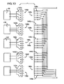
- FIG. 13 is a schematic view of an array of connectors and input devices for the patient monitor.
- the patient monitor may be generally housed in a cabinet 50 as shown in drawing FIGS. 1-3.
- the cabinet may have a front panel 52 with an alpha-numeric display panel 54 , status indicators 56 a - 56 d , and user input switches 58 a - 58 f .
- the cabinet 50 may be of various constructions and configurations, as will be understood by one having ordinary skill in the art. Some exemplary cabinet materials may include, without limitation, stainless steel, powder coated metals, and engineering plastics.
- the alpha-numeric display panel 54 is preferably a liquid crystal display (LCD) although other display devices may be used depending upon a manufacturer's or user's preferences. More particularly, the inventor has found a 16 ⁇ 2 character LCD to perform well in the patient monitor.
- LCD liquid crystal display
- light emitting diodes have been found to perform well for the various status indicators 56 a - 56 d , although other indicators may be substituted.
- indicators for monitor power status (on/off) 56 a for batter power source charging status 56 b , and for an alarm condition 56 c and 56 d relative to a patient monitor have been found to be sufficient and minimally required indicators. Additional indicators may be added and desired by various users, although potential users are cautioned against the inherent confusion that comes with a plethora of indicators.
- a sufficient and minimal array of input switches is also shown in the drawings and includes switches for menu access 58 a , power 58 b , menu scrolling 58 c and 58 d , menu choice entry 58 e , and alarm toggle 58 f .
- Membrane tactile switching or the like is preferred if only because of the ease with which the front panel may be wiped clean. Other switching may also be used with compromises in the ability to clean the front panel around the switches, however. While most of the switches are most preferably accessible on the front panel, the power switch 58 b may alternatively be relocated on the back panel, for example.
- the monitor is preferably provided with an alternative choice between wall plug, also commonly known as line power, and an onboard battery power supply (FIG. 4 ).
- a power cord with an integral transformer and plug may be used as is commonly known to provide an about six volt battery current to the patient monitor.
- the patient monitor may operate a nominal twenty-five hours during a power failure or patient transportation, for example.
- FIG. 4 A circuit for the ability to choose alternative power sources is schematically shown in FIG. 4 .
- the transformer power cord 62 feeds through a circuit breaker 64 to the battery 66 .
- the battery 68 then feeds to an air pump 70 , a power regulator 72 , and a voltage sensor 74 .
- the power regulator may be a switching type regulator of about five volts output, for example.
- the output of the regulator is then used for the electronics 80 of the patient monitor.
- a loop from the battery 68 to the voltage sensor 74 provides monitoring of the power supply and may send a low power signal to the control electronics 80 when battery power drops below a preselected value, as will be understood by one having ordinary skill in the art. This may occur after an extended period of being disconnected from wall power.
- a low power signal alarm may be interpreted as a flashing power indicator 56 a or an audible voice alert.
- the low power alarm will preferably activate at power levels of about twenty-five percent, at fifteen percent, and again at five percent remaining charge. These power levels may be reflected in the power indicator 56 a as increasing flashing frequency.
- the voice alarm may be programmed to state the power level that remains.
- the patient monitor is preferably provide with an air pressure pump 70 and may also have a vacuum pump 80 (FIGS. 5 - 7 ). Alternatively, a manufacturer or user may prefer to omit the vacuum pump 80 or the pressure pump 70 , depending upon their monitoring requirements (FIG. 7 ).
- the pressure pump 70 is useful with infusion bags and may provide a capacity of about 500 mm Hg pressure by connection of an infusion bag air pressure tube with an air pressure connector of the patient monitor.
- Dual redundant air pressure sensors 82 are preferably used to monitor selected and used air pressure within about five percent of a predetermined setting.
- the patient monitor may further be programmed to facilitate a pressure tubing alarm.
- the pressure tubing alarm may sense a blocked or kinked tube when a set pressure is achieved too quickly. Conversely, an open or leaking pressure tube may be sensed when a set pressure takes too long to achieve. Further, a pressure tubing alarm may be set for when either an infusion bag fluid tube or a pressure tube becomes blocked or kinked after a set pressure is properly achieved.
- the vacuum pump 80 is useful with suction canisters by connection of a canister suction tube with a suction connector of the patient monitor.
- a vacuum sensor 84 monitors the selected and used vacuum level within about five percent of a predetermined setting.
- the patient monitor may also be programmed to facilitate vacuum tubing alarms.
- the vacuum tubing alarm may sense a blocked or kinked tube when a set vacuum is achieved too quickly.
- an open or leaking tube may be sensed when a set vacuum takes too long to achieve.
- a vacuum alarm may be set if either a suction canister tube or a vacuum tube becomes block or kinked after a set pressure is properly achieved.
- Infusion bag fluid level monitoring may be provided with a mass differential unit 90 such as is shown in FIG. 10 .
- This type of sensor may also be used for any consumable.
- the fluid bag level sensor 90 preferably has a generally cylindrical housing 92 .
- the housing 92 may be constructed of any suitable structural material, including metals, ceramics, and plastics, for example.
- the housing 92 may further be constructed by any appropriate method that is suitable for the material selected.
- the use of a cylindrical housing 92 may facilitate manufacture by extrusion, for example. Further, the cylindrical shape facilitates cleaning of the sensor.
- the sensor 90 includes a plunger 94 that has a stop 96 , a shaft 98 , and a connector 100 .
- the fluid sensor 90 will commonly be used by hanging the sensor on an I.V. pole or the like as is commonly known.
- the plunger 94 is slideably mounted in the cylinder 92 and slides between extended and retracted positions.
- a helical scale spring 102 or other scalable bias device urges the plunger 94 toward the retracted position.
- a micro switch 104 or the like is preferably mounted to close a sensor circuit when the plunger 94 is in the retracted position.
- the plunger 94 extends when a mass, which may include an infusion fluid bag, is connected with the plunger by connecting the bag with the connector 100 , which may be a hook, for example. Conversely, the bias 102 retracts the plunger 94 when the mass diminishes, indicating consumption of the infusion fluid or other consumable.
- a trip level of the sensor 90 may be made adjustable. As shown, a position of the switch 104 may be adjustable relative to the spring 102 at 200 ml and 500 ml of infusion fluid, for example.
- the trip level of the sensor 90 relative to the content level of the infusion fluid is adjustable by relocating the position of the switch 104 along the cylinder 92 , as will be understood by one having ordinary skill in the art.
- the structure of the sensor 90 may be inverted to sense an accumulation of a used fluid, for example, by either having the switch close when the plunger extends away from the switch 104 or by reprogramming the processor to accept an open switch 104 as a signal criteria. Further yet, the switch 104 may alternatively be placed to contact the plunger stop 96 and close the switch when the plunger is in the extended position.
- FIG. 11 Another fluid accumulation sensor 120 that is useful with suction canisters and the like is shown in FIG. 11 .
- the suction canister level sensor 120 has a plug or stopper 122 that cooperates with an opening in a top or cap of a suction canister.
- a pair of probes 124 and 126 extend in the same general direction from the stopper 122 and extend into a suction canister when the sensor is mounted for use.
- the sensor 120 is connected with the processor by a cord 128 , which may be removable from the stopper 122 .
- the stopper 122 and probes 124 and 126 may be provided as a disposable part, while the cord 128 may be reusable.
- the processor may be programmed to identify a variety of conditions relative to the position of the fluid along the probes 124 and 126 .
- a full condition may be interpreted when the probes 124 and 126 are both first contacted by the fluid.
- the probes 124 and 126 may extend relatively far into the suction canister and a varying resistance between the probes as the fluid level rises may be interpreted by the processor as progressively greater quantities of fluid in the canister.
- Another useful sensor 130 may include a patient motion sensor.
- the patient motion sensor 130 shown in FIG. 12 comprises a piezoelectric coaxial cable 132 , for example.
- the cable 132 is threaded through a pad 134 that is placed under a patient. Electrical signals are generated by the piezoelectric cable 132 because of changes in pressure applied to the piezoelectric cable as the patient moves while laying upon the pad 134 and cable.
- a pad that has a touch sensitive grid may be used. Such a sensor may report specific body position and may be useful in a sleep study, for example.
- the use of a wide variety of sensors is provided in the patient monitor by using keyed input sockets 140 a - 140 e and plugs 142 a - 142 e (FIG. 13 ).
- the cooperating input sockets 140 a - 140 e and plugs 142 a - 142 e are not sensor specific in that a different socket and plug combination are designated for each sensor.
- a socket 140 a - 140 e and plug 142 a - 142 e combination that has a plethora of connectors or contacts 144 a - 144 e and 146 a - 146 e , respectively, is used and a pattern or set of the contacts is identified with a particular sensor, resulting in a smart plug connection of the sensor with the processor.
- An exemplary schematic of five plugs 142 a - 142 e and five sockets 140 a - 140 e is shown in FIG. 13 .
- Each plug 142 a - 142 e and socket 140 a - 140 e arbitrarily has five contacts 144 a - 144 e and 146 a - 146 e , respectively, as shown in FIG. 13 .
- any of the plugs 142 a - 142 e can mate with any of the sockets 140 a - 140 e .
- the sockets 140 a - 140 e are conventionally connected in parallel, so the sockets are electrically identical.
- the processor may be programmed to discern and report as desired virtually any combination of contact input.
- a programming of the processor may dictate a plug wiring of the sensors or vice versa
- a predetermined plug wiring of the sensors may dictate a programming of the processor.
- the processor may be programmed to accommodate a plug 142 a that has contacts 146 a wired for a sensor 90 such as an infusion bag level empty sensor signal, while also accommodating a plug 142 c that has contacts 146 c wired for a sensor 120 such as a suction canister level full signal, for example.
- a plug 142 b that has contacts 146 b wired for a sensor 130 such as a piezoelectric motion sensor input may also be accommodated, for example.
- Other desired sensors may further be accommodated by differentiated wiring of contacts 146 d and 146 e of plugs 142 d and 142 e .
- the wiring of the sensor with the plug 142 a - 142 e and more particularly with the plug contacts 146 a - 146 e and so with the processor through the socket contacts 144 a - 144 e differentiates or identifies the particular sensor.
- a significant feature of this cooperating socket 140 a - 140 e and plug 142 a - 142 e arrangement is that the sensors and the processor may be configured so a preselected sensor can be plugged into any socket 140 a - 140 e without a user wasting time or being distracted or otherwise being confused or making a mistake with regard to identifying the correct socket before plugging in a sensor.
Abstract
Description
Claims (2)
Priority Applications (2)
| Application Number | Priority Date | Filing Date | Title |
|---|---|---|---|
| US09/677,365 US6679840B1 (en) | 1999-09-30 | 2000-10-02 | Patient monitor |
| US10/725,749 US20040111015A1 (en) | 1999-09-30 | 2003-12-02 | Patient monitor |
Applications Claiming Priority (2)
| Application Number | Priority Date | Filing Date | Title |
|---|---|---|---|
| US15685699P | 1999-09-30 | 1999-09-30 | |
| US09/677,365 US6679840B1 (en) | 1999-09-30 | 2000-10-02 | Patient monitor |
Related Child Applications (1)
| Application Number | Title | Priority Date | Filing Date |
|---|---|---|---|
| US10/725,749 Continuation-In-Part US20040111015A1 (en) | 1999-09-30 | 2003-12-02 | Patient monitor |
Publications (1)
| Publication Number | Publication Date |
|---|---|
| US6679840B1 true US6679840B1 (en) | 2004-01-20 |
Family
ID=30002607
Family Applications (1)
| Application Number | Title | Priority Date | Filing Date |
|---|---|---|---|
| US09/677,365 Expired - Fee Related US6679840B1 (en) | 1999-09-30 | 2000-10-02 | Patient monitor |
Country Status (1)
| Country | Link |
|---|---|
| US (1) | US6679840B1 (en) |
Cited By (1)
| Publication number | Priority date | Publication date | Assignee | Title |
|---|---|---|---|---|
| US20130211378A1 (en) * | 2012-02-14 | 2013-08-15 | Paul Joseph Miller | Pump and monitor for iv pressure infusers |
Citations (22)
| Publication number | Priority date | Publication date | Assignee | Title |
|---|---|---|---|---|
| US3949753A (en) | 1972-11-27 | 1976-04-13 | Rolf Dockhorn | Apparatus for supplying aseptic fluids |
| US4633237A (en) | 1984-07-11 | 1986-12-30 | Kenneth A. Tucknott | Patient bed alarm system |
| US4676776A (en) | 1985-01-18 | 1987-06-30 | Intelligent Medicine, Inc. | Device and method for effecting application of a therapeutic agent |
| WO1988007384A1 (en) | 1987-03-30 | 1988-10-06 | Kanthal Medical Heating Ab | Apparatus for heating and mixing transfusion or infusion liquid, particularly blood |
| US4810243A (en) | 1985-01-18 | 1989-03-07 | Intelligent Medicine, Inc. | Device and method for effecting application of a therapeutic agent |
| US5121107A (en) | 1990-07-25 | 1992-06-09 | John Newell | Intravenous supply alarm assembly |
| US5147310A (en) | 1990-11-13 | 1992-09-15 | Giannini Peter T | Pressure infusion system |
| WO1994011054A1 (en) | 1992-11-09 | 1994-05-26 | Sipin Anatole J | Controlled fluid transfer system |
| US5558638A (en) | 1993-04-30 | 1996-09-24 | Healthdyne, Inc. | Patient monitor and support system |
| US5563584A (en) | 1993-11-15 | 1996-10-08 | The Johns Hopkins University | Liquid level sensing and monitoring system for medical fluid infusion systems |
| US5573506A (en) | 1994-11-25 | 1996-11-12 | Block Medical, Inc. | Remotely programmable infusion system |
| US5582601A (en) | 1994-09-12 | 1996-12-10 | Surgin Surgical Instrumentation, Inc. | Cassette for receiving aspirated fluids |
| US5590648A (en) * | 1992-11-30 | 1997-01-07 | Tremont Medical | Personal health care system |
| US5658250A (en) | 1993-07-13 | 1997-08-19 | Sims Deltec, Inc. | Systems and methods for operating ambulatory medical devices such as drug delivery devices |
| US5673691A (en) * | 1991-01-11 | 1997-10-07 | Pics, Inc. | Apparatus to control diet and weight using human behavior modification techniques |
| US5683367A (en) | 1995-03-06 | 1997-11-04 | Sabratek Corporation | Infusion pump with different operating modes |
| US5687734A (en) * | 1994-10-20 | 1997-11-18 | Hewlett-Packard Company | Flexible patient monitoring system featuring a multiport transmitter |
| US5792109A (en) | 1994-09-01 | 1998-08-11 | Leland L. Ladd | Irrigation pump and system |
| US5957838A (en) * | 1996-07-02 | 1999-09-28 | Instrumentarium Oy | Patient monitoring system |
| US5967975A (en) * | 1997-11-13 | 1999-10-19 | Ridgeway; Donald G. | Home health parameter monitoring system |
| US6029078A (en) * | 1996-03-26 | 2000-02-22 | Hologic, Inc. | System for assessing bone characteristics |
| US6050940A (en) * | 1996-06-17 | 2000-04-18 | Cybernet Systems Corporation | General-purpose medical instrumentation |
-
2000
- 2000-10-02 US US09/677,365 patent/US6679840B1/en not_active Expired - Fee Related
Patent Citations (23)
| Publication number | Priority date | Publication date | Assignee | Title |
|---|---|---|---|---|
| US3949753A (en) | 1972-11-27 | 1976-04-13 | Rolf Dockhorn | Apparatus for supplying aseptic fluids |
| US4633237A (en) | 1984-07-11 | 1986-12-30 | Kenneth A. Tucknott | Patient bed alarm system |
| US4676776A (en) | 1985-01-18 | 1987-06-30 | Intelligent Medicine, Inc. | Device and method for effecting application of a therapeutic agent |
| US4810243A (en) | 1985-01-18 | 1989-03-07 | Intelligent Medicine, Inc. | Device and method for effecting application of a therapeutic agent |
| WO1988007384A1 (en) | 1987-03-30 | 1988-10-06 | Kanthal Medical Heating Ab | Apparatus for heating and mixing transfusion or infusion liquid, particularly blood |
| US5121107A (en) | 1990-07-25 | 1992-06-09 | John Newell | Intravenous supply alarm assembly |
| US5147310A (en) | 1990-11-13 | 1992-09-15 | Giannini Peter T | Pressure infusion system |
| US5673691A (en) * | 1991-01-11 | 1997-10-07 | Pics, Inc. | Apparatus to control diet and weight using human behavior modification techniques |
| WO1994011054A1 (en) | 1992-11-09 | 1994-05-26 | Sipin Anatole J | Controlled fluid transfer system |
| US5590648A (en) * | 1992-11-30 | 1997-01-07 | Tremont Medical | Personal health care system |
| US5558638A (en) | 1993-04-30 | 1996-09-24 | Healthdyne, Inc. | Patient monitor and support system |
| US5658250A (en) | 1993-07-13 | 1997-08-19 | Sims Deltec, Inc. | Systems and methods for operating ambulatory medical devices such as drug delivery devices |
| US5563584A (en) | 1993-11-15 | 1996-10-08 | The Johns Hopkins University | Liquid level sensing and monitoring system for medical fluid infusion systems |
| US5792109A (en) | 1994-09-01 | 1998-08-11 | Leland L. Ladd | Irrigation pump and system |
| US5582601A (en) | 1994-09-12 | 1996-12-10 | Surgin Surgical Instrumentation, Inc. | Cassette for receiving aspirated fluids |
| US5687734A (en) * | 1994-10-20 | 1997-11-18 | Hewlett-Packard Company | Flexible patient monitoring system featuring a multiport transmitter |
| US5573506A (en) | 1994-11-25 | 1996-11-12 | Block Medical, Inc. | Remotely programmable infusion system |
| US5683367A (en) | 1995-03-06 | 1997-11-04 | Sabratek Corporation | Infusion pump with different operating modes |
| US6029078A (en) * | 1996-03-26 | 2000-02-22 | Hologic, Inc. | System for assessing bone characteristics |
| US6050940A (en) * | 1996-06-17 | 2000-04-18 | Cybernet Systems Corporation | General-purpose medical instrumentation |
| US6375614B1 (en) * | 1996-06-17 | 2002-04-23 | Cybernet Systems Corporation | General-purpose medical istrumentation |
| US5957838A (en) * | 1996-07-02 | 1999-09-28 | Instrumentarium Oy | Patient monitoring system |
| US5967975A (en) * | 1997-11-13 | 1999-10-19 | Ridgeway; Donald G. | Home health parameter monitoring system |
Cited By (3)
| Publication number | Priority date | Publication date | Assignee | Title |
|---|---|---|---|---|
| US20130211378A1 (en) * | 2012-02-14 | 2013-08-15 | Paul Joseph Miller | Pump and monitor for iv pressure infusers |
| US9345830B2 (en) * | 2012-02-14 | 2016-05-24 | Sprout Medical, Inc. | Pump and monitor for IV pressure bag infusers |
| US10130764B2 (en) | 2012-02-14 | 2018-11-20 | Sprout Medical, Inc | Pump and monitor for IV pressure bag infusers |
Similar Documents
| Publication | Publication Date | Title |
|---|---|---|
| US6270478B1 (en) | Infusion pump system and an infusion pump unit | |
| US4394862A (en) | Metering apparatus with downline pressure monitoring system | |
| KR100643086B1 (en) | Apparatus for infusion management | |
| US6348777B1 (en) | Power management system | |
| EP1362606A1 (en) | Syringe pump and liquid infusing method | |
| JP2003220137A (en) | Battery gauge | |
| US11168840B1 (en) | Electronic pressure gauge for pressurized system with variable outlet flows | |
| CN1330527A (en) | Hazard monitor for surgical tourniquet systems | |
| JPH031876A (en) | Pump apparatus for medical treatment | |
| AU2001241792A1 (en) | Power management system | |
| US9872958B2 (en) | Administration device having a patient state monitor | |
| KR20170118585A (en) | Urine Emission Measurement Device | |
| IE70750B1 (en) | Liquid delivery device | |
| US7127943B1 (en) | Method and apparatus for detection of fluid level in a container | |
| EP3781324B1 (en) | Controller for an aerosol generator | |
| US6679840B1 (en) | Patient monitor | |
| JP2001245978A (en) | Syringe pump and drive controlling method in obstruction detection time | |
| JP2004000498A (en) | Transfusion device | |
| JP2001245974A (en) | Syringe pump and obstruction pressure detecting method | |
| KR100792805B1 (en) | A liquid level sensor of liquid medication injection set | |
| US20040111015A1 (en) | Patient monitor | |
| KR20040107765A (en) | Ringer hangning uuit | |
| KR20230016565A (en) | Capacitive level sensing apparatus and method | |
| CN117205400A (en) | Injection key, injection device with skin contact detection function and control method thereof | |
| WO2000042395A1 (en) | Method and apparatus for detection of a fluid level in a container |
Legal Events
| Date | Code | Title | Description |
|---|---|---|---|
| AS | Assignment |
Owner name: LADD, LELAND L., FLORIDA Free format text: ASSIGNMENT OF ASSIGNORS INTEREST;ASSIGNOR:LADD, LELAND L.;REEL/FRAME:012623/0238 Effective date: 20010928 Owner name: LADD, BARBARA J., FLORIDA Free format text: ASSIGNMENT OF ASSIGNORS INTEREST;ASSIGNOR:LADD, LELAND L.;REEL/FRAME:012623/0238 Effective date: 20010928 |
|
| REMI | Maintenance fee reminder mailed | ||
| REIN | Reinstatement after maintenance fee payment confirmed | ||
| FP | Lapsed due to failure to pay maintenance fee |
Effective date: 20080120 |
|
| FEPP | Fee payment procedure |
Free format text: PETITION RELATED TO MAINTENANCE FEES GRANTED (ORIGINAL EVENT CODE: PMFG); ENTITY STATUS OF PATENT OWNER: SMALL ENTITY Free format text: PETITION RELATED TO MAINTENANCE FEES FILED (ORIGINAL EVENT CODE: PMFP); ENTITY STATUS OF PATENT OWNER: SMALL ENTITY |
|
| PRDP | Patent reinstated due to the acceptance of a late maintenance fee |
Effective date: 20091118 |
|
| FPAY | Fee payment |
Year of fee payment: 4 |
|
| SULP | Surcharge for late payment | ||
| REMI | Maintenance fee reminder mailed | ||
| LAPS | Lapse for failure to pay maintenance fees | ||
| STCH | Information on status: patent discontinuation |
Free format text: PATENT EXPIRED DUE TO NONPAYMENT OF MAINTENANCE FEES UNDER 37 CFR 1.362 |
|
| FP | Lapsed due to failure to pay maintenance fee |
Effective date: 20120120 |