US6676641B2 - Retractable hypodermic syringe - Google Patents
Retractable hypodermic syringe Download PDFInfo
- Publication number
- US6676641B2 US6676641B2 US09/948,061 US94806101A US6676641B2 US 6676641 B2 US6676641 B2 US 6676641B2 US 94806101 A US94806101 A US 94806101A US 6676641 B2 US6676641 B2 US 6676641B2
- Authority
- US
- United States
- Prior art keywords
- plunger
- assembly
- barrel
- seal
- plunger assembly
- Prior art date
- Legal status (The legal status is an assumption and is not a legal conclusion. Google has not performed a legal analysis and makes no representation as to the accuracy of the status listed.)
- Expired - Fee Related, expires
Links
Images


Classifications
-
- A—HUMAN NECESSITIES
- A61—MEDICAL OR VETERINARY SCIENCE; HYGIENE
- A61M—DEVICES FOR INTRODUCING MEDIA INTO, OR ONTO, THE BODY; DEVICES FOR TRANSDUCING BODY MEDIA OR FOR TAKING MEDIA FROM THE BODY; DEVICES FOR PRODUCING OR ENDING SLEEP OR STUPOR
- A61M5/00—Devices for bringing media into the body in a subcutaneous, intra-vascular or intramuscular way; Accessories therefor, e.g. filling or cleaning devices, arm-rests
- A61M5/178—Syringes
- A61M5/31—Details
- A61M5/32—Needles; Details of needles pertaining to their connection with syringe or hub; Accessories for bringing the needle into, or holding the needle on, the body; Devices for protection of needles
- A61M5/3205—Apparatus for removing or disposing of used needles or syringes, e.g. containers; Means for protection against accidental injuries from used needles
- A61M5/321—Means for protection against accidental injuries by used needles
- A61M5/322—Retractable needles, i.e. disconnected from and withdrawn into the syringe barrel by the piston
- A61M5/3232—Semi-automatic needle retraction, i.e. in which triggering of the needle retraction requires a deliberate action by the user, e.g. manual release of spring-biased retraction means
-
- A—HUMAN NECESSITIES
- A61—MEDICAL OR VETERINARY SCIENCE; HYGIENE
- A61M—DEVICES FOR INTRODUCING MEDIA INTO, OR ONTO, THE BODY; DEVICES FOR TRANSDUCING BODY MEDIA OR FOR TAKING MEDIA FROM THE BODY; DEVICES FOR PRODUCING OR ENDING SLEEP OR STUPOR
- A61M5/00—Devices for bringing media into the body in a subcutaneous, intra-vascular or intramuscular way; Accessories therefor, e.g. filling or cleaning devices, arm-rests
- A61M5/178—Syringes
- A61M5/31—Details
- A61M5/315—Pistons; Piston-rods; Guiding, blocking or restricting the movement of the rod or piston; Appliances on the rod for facilitating dosing ; Dosing mechanisms
- A61M5/31511—Piston or piston-rod constructions, e.g. connection of piston with piston-rod
-
- A—HUMAN NECESSITIES
- A61—MEDICAL OR VETERINARY SCIENCE; HYGIENE
- A61M—DEVICES FOR INTRODUCING MEDIA INTO, OR ONTO, THE BODY; DEVICES FOR TRANSDUCING BODY MEDIA OR FOR TAKING MEDIA FROM THE BODY; DEVICES FOR PRODUCING OR ENDING SLEEP OR STUPOR
- A61M5/00—Devices for bringing media into the body in a subcutaneous, intra-vascular or intramuscular way; Accessories therefor, e.g. filling or cleaning devices, arm-rests
- A61M5/178—Syringes
- A61M5/31—Details
- A61M5/32—Needles; Details of needles pertaining to their connection with syringe or hub; Accessories for bringing the needle into, or holding the needle on, the body; Devices for protection of needles
- A61M5/34—Constructions for connecting the needle, e.g. to syringe nozzle or needle hub
- A61M5/347—Constructions for connecting the needle, e.g. to syringe nozzle or needle hub rotatable, e.g. bayonet or screw
Definitions
- the field of the present invention is hypodermic syringes with safety systems for the avoidance of sharps injuries.
- the art has recognized the desirability of protecting personnel from accidental sharps injuries, or needle sticks, and against contact with fluid that leaks, drips or is sprayed from a syringe after the syringe is used to deliver an injection.
- some fluid remains in the syringe, particularly at the tip of the needle.
- This fluid may include the fluid injected into the patient from the syringe and/or body fluids from the patient such as blood. Any fluid remaining in the syringe after use of the syringe may leave the syringe, such as by leaking, spraying or dripping from the syringe and may contact persons or objects in the area.
- Syringes with retractable needles may be especially prone to this loss of fluid when the needle quickly retracts into the barrel of the syringe after injection.
- the present invention is directed to apparatus and methods of operation for hypodermic syringe systems with retractable needles.
- the syringe includes a barrel and a plunger assembly slidably extending into the barrel with features and steps permitting further manipulation of the plunger following injection to retract a luer hub assembly and needle into the barrel.
- the plunger assembly includes a hollow outer plunger assembly, a hollow inner plunger assembly and a resilient tension element extending between the two assemblies which is just substantially relaxed with the outer and inner plunger assemblies telescoped together. A releasable engagement between the outer and inner plunger assemblies is able to retain the assemblies telescoped to an extended position.
- a collapsible plunger is provided.
- the first separate aspect may be further contemplated to include a socket on the outer plunger assembly and a resiliently mounted pin on the inner plunger assembly which engage with the plunger assemblies telescoped to an extended position.
- the barrel of the syringe may include a release element to engage the releasable engagement through manipulation of the plunger. Such manipulation may include extra force or torque on the plunger thumb button. Avoidance of required manipulation with the other hand or adjacent the needle can be avoided.
- the first separate aspect is further contemplated to include indexing between the inner and outer plunger assemblies, a stop between the barrel at the plunger opening and the inner plunger assembly at its locking end and selective indexing between the overall plunger assembly and the barrel.
- the plunger assembly includes a plunger and a cap at one end of the plunger.
- the cap has a cylindrical wall with a helical cam surface and a track extending longitudinally of the plunder assembly.
- the plunger includes a resiliently mounted lock that retains the cap and the plunger from rotating relative to one another.
- the resiliently mounted lock includes a disengagement ramp.
- the barrel includes an internal rail which is able to interfere with the resiliently mounted lock at the disengagement ramp to displace the lock from the track upon near full insertion of the plunger in the barrel. This displacement is able to fix the cap from rotating relative to the barrel and release the plunger to rotate relative to the cap.
- the helical cam surface is able to interact with a follower pin on the plunger to rotate the plunger relative to the barrel while the cap remains from rotating relative to the barrel. In this way, rotation may be selectively employed to actuate the syringe retraction mechanism and otherwise the plunger remains indexed relative to the barrel during charging and injecting operations.
- the plunger includes a probe extending from the seal end of the plunger.
- a seal stop is positioned about the probe and is held thereto by an axially releasable engagement between the probe and the stop.
- An annular seal is positioned between the plunger at the seal end and the seal stop. The seal is found to be in sealed engagement with the internal sidewall of the barrel with the seal stop in mated engagement with the plunger and in disengagement with the internal sidewall when the seal stop is disengaged from the plunger. The ability to reduce seal friction between the plunger and the barrel for needle retraction can thus be achieved.
- the plunger assembly includes a probe at the seal end with a retainer lug on the probe.
- a luer hub assembly is positioned in the barrel with a body having a needle end, an engagement end, a means to retain a needle and a retainer surface which faces the body near the engagement end and is engagable with the retainer lug through rotation of the plunger.
- the plunger may thus be coupled with the entire luer hub assembly for further manipulation.
- the retainer surface and the retainer lug may be axially displaced from one another with the plunger assembly fully extended into the barrel even though the retainer lug is aligned in engagement with the retainer surface.
- the spacing is able to allow for a short retraction of the plunger prior to drawing on the luer hub assembly. This retraction is capable of being employed to void an associated needle of fluid.
- the plunger assembly includes a probe extending axially from the seal end of the plunger.
- a seal stop is positioned about the probe. An axially releasable engagement enables the seal stop to be retained in mated relationship with the seal end of the plunger as well as axially released therefrom.
- the seal stop provides a vehicle for accomplishing functions advantageous for luer hub and needle retraction.
- the seventh separate aspect is contemplated to further include a portion inwardly tapered on the internal sidewall of the barrel to cooperate with a seal about the luer hub assembly. Extraction of the luer hub assembly through the barrel can operate through the taper to gradually release the seal about the body of the luer hub assembly, reducing initial acceleration imposed on a retracting needle. Reduced acceleration can limit the amount of liquid separated from the needle during retraction.
- a seal stop is associated with the seal end of the plunger assembly.
- the seal stop includes an inwardly facing cam surface facing a luer hub assembly which includes a latch pin engagable with an internal stop and having a cam follower engagable with the inwardly facing cam surface. The releasable seal stop is thus able to actuate the latch pin to release the luer hub assembly within the barrel from the internal stop.
- the ninth separate aspect is contemplated to further include mutually engaging surfaces between the seal stop and the luer hub assembly able to draw the seal stop and the luer hub assembly toward one another to actuate the resiliently mounted latch pin.
- the seal stop releasably engaged with the seal end of the plunger can be released to become engaged with the luer hub assembly for release of the luer hub assembly from the barrel.
- a hypodermic syringe retraction method includes extending the plunger assembly and a resilient tension element within the barrel of the syringe where the plunger assembly includes an outer plunger and an inner plunger telescoped together.
- the outer plunger is drawn outwardly from the barrel to engage an engagement between the outer and inner plungers. The engagement between the outer and inner plungers is later released.
- the eleventh separate aspect of the present invention is further contemplated to include engaging the luer hub assembly with the plunger assembly by rotating a retainer log of the plunger assembly into spaced engagement with a retainer surface on the luer hub assembly.
- the eleventh and twelfth separate aspects of the present invention are further contemplated to include axial pushing of a plunger cap and translating the actual push to rotation of the plunger assembly.
- a seal stop releasably engaged on the seal end of the plunger is released to radially retract an annular seal held between the seal end of the plunger and the seal stop.
- the seal stop is also engaged with a luer hub assembly and the luer hub assembly is released from the barrel. With the annular seal retracted and the luer hub released, extraction of the luer hub from the end of the barrel is possible.
- a seal stop is released from the seal end of the plunger which allows for radial retraction of a seal associated therewith.
- the seal stop is engaged with a luer hub assembly and drawn thereto through rotation of the seal stop.
- the drawing of the seal stop toward the luer hub assembly releases a latch pin engaged with the interior of the barrel.
- any of the foregoing separate aspects are contemplated to be employed in combination to greater advantage.
- FIG. 1 is a perspective view of an assembled syringe.
- FIG. 2 is a side view of the assembled syringe.
- FIG. 3 is a cross-sectional view of the assembled syringe.
- FIG. 4 is a perspective view of a syringe barrel.
- FIG. 5 is a side view of the syringe barrel.
- FIG. 6 is a cross section of the syringe barrel taken along line 6 — 6 of FIG. 5 .
- FIG. 7 is a top view of the syringe barrel.
- FIG. 8 is a bottom view of the syringe barrel.
- FIG. 9 is a perspective view of an outer plunger.
- FIG. 10 is a side view of the outer plunger.
- FIG. 11 is a side view of the outer plunger.
- FIG. 12 is a bottom view of the outer plunger.
- FIG. 13 is a perspective view of a plunger cap.
- FIG. 14 is a side view of the plunger cap.
- FIG. 15 is a side view of the plunger cap.
- FIG. 16 is a bottom view of the plunger cap.
- FIG. 17 is a perspective view of an inner plunger.
- FIG. 18 is a side view of the inner plunger.
- FIG. 19 is a side view of the inner plunger.
- FIG. 20 is a top view of the inner plunger.
- FIG. 21 is a bottom view of the inner plunger.
- FIG. 22 is a perspective view of a resilient tension element.
- FIG. 23 is a perspective view of a seal stop.
- FIG. 24 is a top view of the seal stop.
- FIG. 25 is a side view of the seal stop.
- FIG. 26 is a perspective view of a luer hub assembly.
- FIG. 27 is a top view of the luer hub assembly.
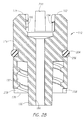
- FIG. 28 is a cross-sectional view taken along line 28 — 28 of FIG. 27 .
- FIG. 29 is a cross-sectional view taken along line 29 — 29 of FIG. 27 .
- FIG. 30 is a partial side view of a seal stop and luer hub assembly in a first position.
- FIG. 31 is a perspective view of the seal stop and luer hub assembly in a second position.
- FIG. 32 is a perspective view of the seal stop and a probe.
- FIG. 33 is a side view of the seal stop and luer hub assembly in another position.
- a hypodermic syringe generally designated 20 in FIG. 1, includes a barrel 22 having a plunger opening 24 at a first, larger end and a needle opening 26 at a second, smaller end.
- the barrel 22 includes an internal sidewall which may be defined in terms of hollow portions based on variations in internal diameter as separately illustrated in FIGS. 4 through 8.
- a first hollow portion 28 extends from the plunger opening 24 to a first inward transition portion 30 .
- This first portion 28 has two longitudinally extending internal rails 32 . These rails extend the length of the first portion 28 with a ramp 34 at the plunger opening 24 . The rails each extend inwardly only to the inner diameter of the transition portion 30 and terminate at that point.
- An inwardly extending plunger stop 36 is located spaced from the inward transition portion 30 in the first hollow portion 28 and extends inwardly beyond the minimum diameter of the inward transition portion 30 .
- a flange extending outwardly from the barrel 22 at the transition portion 30 defines a finger grip 38 .
- the finger grip 38 may be configured and located to satisfy various ergonomic requirements.
- a second hollow portion 40 extends from the inward transition portion 30 of the first hollow portion 28 to a second inward transition portion 42 .
- This second hollow portion 40 is shown to have a diameter which is less than the first hollow portion 28 .
- a plunger guide 44 extends inwardly from the second hollow portion 40 immediately adjacent the first inward transition portion 30 .
- Two release elements 46 are arranged diametrically on the interior of the hollow portion 40 near the inward transition portion 42 . These release elements 46 are inwardly extending ramps as can be seen in FIG. 7 .
- a third hollow portion 48 of the barrel 22 extends from the inward transition portion 42 .
- This third hollow portion 48 has an inner diameter less than that of the second hollow portion 40 .
- This portion terminates in an inward transition portion 50 . Otherwise, the interior of the hollow portion 48 is without inwardly extending elements.
- a fourth hollow portion 52 extends from the inward transition portion 50 of the third hollow portion 48 to the needle opening 26 .
- the fourth hollow portion 52 includes two diametrically placed internal stops 54 .
- These stops 54 define cavities with the edge most distant from the needle opening 26 providing a shoulder against which a luer hub assembly can be retained.
- the internal stops 54 are of sufficient depth that a profile 56 is shown on the outside surface of the barrel 22 for each stop to accommodate the inset.
- Two luer hub stops 58 diametrically positioned are located at the needle opening 26 and extend inwardly for indexing and restricting axial extraction of a luer hub assembly positioned in the fourth hollow portion 52 .
- a portion 60 of the internal wall of the barrel 22 within the fourth hollow portion 52 is inwardly tapered toward the needle opening 26 .
- the taper expands toward the internal stops 54 to release the seal of an O-ring positioned about a luer hub assembly located in the hollow portion 52 as it is extracted through the barrel and into the third hollow portion 38 .
- a plunger assembly slidably extends into the barrel 22 .
- This plunger assembly includes a hollow outer plunger assembly which telescopes together with a hollow inner plunger assembly.
- the hollow outer plunger assembly includes a plunger cap and a hollow outer plunger.
- the hollow outer plunger 62 illustrated in FIGS. 9 through 12, includes a cap end 64 and a locking end 66 .
- the outer plunger 62 is generally cylindrical in body with a number of engaging elements and grooves located thereabout and therethrough. The diameter of the outer plunger 62 slides easily within the second hollow portion 40 .
- Two diametrically arranged longitudinal guide grooves 68 extend substantially but not fully the length of the hollow outer plunger 62 .
- a stop groove 70 also extends through the side of the outer plunger 62 at 90° to the guide grooves 68 . This groove 70 extends a bit further toward the cap end 64 than the guide groves 68 .
- a ramp 71 is located at the lower end of the stop groove 70 .
- a longitudinal indexing groove 72 is positioned in the quadrant of the outer plunger 62 which does not have a guide groove 68 or the stop groove 70 .
- the indexing groove 72 does not extend fully through the wall of the outer plunger 62 , unlike the guide grooves 68 and the stop groove 70 .
- a lateral release 74 extends circumferentially from the end of the indexing groove 72 most adjacent the cap end 64 of the outer plunger 62 .
- the indexing groove 72 receives the plunger guide 44 extending inwardly from the second hollow portion 40 .
- the plunger guide 44 and the longitudinal indexing groove 72 cooperate to index the outer plunger 62 to prevent relative rotation between the outer plunger 62 and the barrel 22 .
- This indexing constraint does not include the circumstance where the outer plunger 62 extends fully into the barrel 22 such that the plunger guide 44 meets the lateral release 74 .
- the longitudinal indexing groove 72 at the locking end 66 of the outer plunger 62 includes a guide stop 76 .
- the guide stop 76 extends laterally across the indexing groove 72 such that it has some flexibility allowing axial insertion of the outer plunger 62 into the barrel 22 with the plunger guide 44 being forced past the guide stop 76 .
- the plunger guide 44 constrains the outer plunger 62 from rotation relative to the barrel 22 except at the lateral release 74 and prevents extraction through interference of the guide stop 76 .
- sockets 78 Adjacent the locking end 66 of the outer plunger 62 , opposed sockets 78 extend through the wall of the plunger. These sockets 78 are each displaced from the corresponding longitudinal guide grooves 68 by a catch 80 . The catch 80 continues a portion of the groove to a certain depth on the inner side of the sidewall of the outer plunger 62 for indexing purposes.
- One end of each of the sockets 78 is open angularly about the hollow outer plunger 62 to form an entrance 82 for the release elements 46 forming an inwardly extending ramp which cooperates with the entrance 82 .
- follower pins 84 extend outwardly diametrically across the plunger 62 .
- resiliently mounted locks 86 extend radially outwardly from the outer plunger 62 . These locks 86 are mounted with axial cuts through the sidewall of the outer plunger 62 so that they may more easily be forced inwardly.
- the locks have disengagement ramps 88 on the ends displaced from the cap end 64 of the outer plunger 62 .
- the outer plunger assembly further includes a plunger cap 90 illustrated in FIGS. 13 through 16.
- the plunger cap 90 includes a thumb button 92 on one end and a cylindrical wall 94 depending therefrom.
- Centrally mounted within the cylindrical wall 94 is a first attachment 96 defining a socket with an undercut opening to retain the resilient cylindrical end of a bungee therein.
- the cylindrical wall 94 includes opposed tracks 98 cut axially therein. The tracks are sized and positioned to receive the resiliently mounted locks 86 with the cylindrical wall 94 of the cap 90 positioned on the outer plunger 62 at the cap end 64 .
- the cylindrical wall further includes two diametrically opposed helical cam grooves 100 forming helical cam surfaces to receive the follower pins 84 which engage and are slidable against the helical cam surfaces.
- the tracks 98 will also be found to be arranged and sized to receive the longitudinally extending internal rails 32 of the hollow portion 28 of the barrel 22 .
- the plunger assembly further includes a hollow inner plunger assembly 102 illustrated in FIGS. 17 through 21.
- the body of this plunger assembly 102 is defined by three longitudinally extending arms 104 , 106 , 108 .
- the three arms 104 , 106 , 108 extend at 90° to one another leaving one quadrant empty.
- the lengths of the arms 104 , 106 , 108 provide resilience allowing, among other things, inward movement for assembly of the inner plunger 102 with the outer plunger 62 .
- a circular hub 110 is located at the seal end 112 of the plunger 102 while the engagement end 114 is open.
- the arms 104 , 106 , 108 extend from the circular hub 110 .
- a second attachment 116 receives a second resilient cylindrical end of a bungee.
- This attachment 116 provides a socket which can be entered from the side with the bungee extending through an open channel 118 .
- the first end of the bungee may be forced or molded into the first attachment 96 .
- a bungee 120 operating as a resilient tension element, is shown in FIG. 22 to include two resilient cylindrical ends 122 , 124 providing first and second anchor shoulders with a central resilient shaft 126 . Molded elastomeric material is contemplated for the bungee 120 . Such materials typically yield over time when in tension. Consequently, it is appropriate to avoid tension in the resilient tension element 120 until use. With the outer plunger 62 and the inner plunger 102 assembled and telescoped together, the resilient tension element 120 is preferably just substantially relaxed such that it will not experience significant yield between the times of assembly and use. Therefore, the state of being just substantially relaxed may include minimal tension or may include a small amount of slack.
- Two resiliently mounted pins 128 and 130 extend radially outwardly from the distal ends of the longitudinally extending arms 104 and 106 . These two arms are identical.
- the pins 128 , 130 engage the two longitudinal guide grooves 68 through the wall of the outer plunger 62 .
- the cooperation of the pins 128 and 130 with the guide grooves 68 stabilize the telescoping movement of the inner plunger 102 with the outer plunger 62 and index the two plungers from rotating relative to one another.
- the pins 128 and 130 may each also engage and overcome a catch 80 to then spring outwardly into the opposed sockets 78 .
- the sockets 78 along with the resiliently mounted pins 128 and 130 define a releasable engagement between the outer plunger 62 and the inner plunger 102 . Once the releasable engagement is engaged, it is only released through the extension of the plunger assembly fully into the barrel 22 to align the release elements 46 with the sockets 78 . Rotation of the plunger assembly causes the entrances 82 to pass over the release elements 46 . The resiliently mounted pins 128 and 130 then engage the release elements 46 and are forced inwardly to such an extent that the resiliently mounted pins 128 and 130 are each free of the adjacent catch 80 .
- the release of the resiliently mounted pins 128 and 130 allows the outer plunger 62 and the inner plunger 102 to telescope together if not otherwise constrained.
- a radially extending stop 132 is resiliently mounted to the inner plunger assembly 110 by the longitudinally extending arm 108 adjacent the engagement end 114 of the inner plunger 102 .
- This stop 132 is able to move longitudinally within the stop groove 70 and also can provide indexing to prevent rotation between the outer plunger 62 and the inner plunger 102 .
- the radially extending stop 132 extends through this stop groove 70 and is aligned with and can engage the plunger stop 36 in the space between the plunger stop 36 and the transition portion 30 . This limits the travel of the inner plunger assembly 102 so as not to exit the barrel 22 . Further, the transition portion 30 prevents travel of the inner plunger 102 through the engagement of the underside of the stop 132 .
- the stop 132 includes a release ramp 133 .
- This ramp 133 is positioned to be engaged by the ramp 71 at the end of the stop groove 70 to release the stop pin 132 from the plunger stop 36 with the outer plunger 62 and the inner plunger 102 telescoped to an extended position.
- a probe 134 extends axially from the seal end 112 of the inner plunger 102 and is attached to the circular hub 110 .
- a cavity 136 having a truncated conical surface extends into the seal end 112 about the probe 134 .
- an external truncated conical surface 138 extends to the rim of the circular hub 110 .
- the probe 134 includes three specific engagement mechanisms.
- Two retainer lugs 140 extend outwardly near the distal end of the plunger 134 .
- Bayonet slots 142 diametrically opposed are defined by a first circumferentially extending groove 144 and an axially extending groove 146 .
- a ridge 148 reduces the depth of the bayonet slot 142 between the groove 144 and the groove 146 . Consequently, some resistance to circumferential movement of a pin within the groove is intended before reaching axial release.
- outwardly and axially extending shoulders are defined by two diametrically opposed lugs 150 each extending about a portion of the shaft of the probe 134 .
- a conical seal stop 152 illustrated in FIGS. 23 through 25, includes a central bore 154 to receive the probe 134 and is surrounded by a truncated conical surface 156 .
- the truncated conical surface 156 is able to extend into and mate with the truncated conical surface of the cavity 136 on the seal end 112 of the inner plunger 102 .
- a number of engagement means are provided on the seal stop 152 .
- Slots 158 extend outwardly from the central bore 154 to define inwardly and axially extending shoulders 160 .
- the slots 158 loosely receive the lugs 150 such that axial rotation of the probe 134 relative to the seal stop 152 can occur.
- At least a portion of the surface at diametrically opposed locations on the side of the seal stop 152 facing away from the seal end 112 of the inner plunger 102 forms two inwardly facing cam surfaces 162 . These surfaces are inclined inwardly from the outer rim of the seal stop 152 .
- Resiliently mounted bayonet pins 164 extend inwardly from diametrically opposed positions. These bayonet pins 164 , in cooperation with the bayonet slots 142 located on the probe 134 , define an axially releasable engagement. The resilience of the mounts 165 for the pins 164 allows the pins 164 to move outwardly to surmount the ridges 148 in the bayonet slots 142 . Thus, under a torque load, the probe 134 is able to rotate relative to the seal stop 152 to move the bayonet pins 164 from the axially engaged position in the circumferential grooves 144 to an axially disengaged position in the axial grooves 146 .
- the relative motion between the probe 134 and the slots 158 is allowed by the slots 158 being wider than the lugs 150 and angularly arranged such that the inwardly and axially extending shoulders 160 do not engage the outwardly and axially extending shoulders of the lugs 150 until the bayonet pins 164 have moved over the ridges 148 to the axial extending grooves 146 of the bayonet slots 142 .
- two support elements 166 extend axially from the conical seal stop 152 away from the seal end 112 of the inner plunger 102 .
- These supports 166 include first engagement surfaces 168 which are inclined relative to the axis of the seal stop 152 and face the seal stop 152 .
- An annular seal 170 is positioned between the seal end 112 of the inner plunger 102 and the seal stop 152 .
- the seal stop 152 With the seal stop 152 in mating engagement with the seal end 112 , the external truncated conical surface 138 and the truncated conical surface 156 together provide a groove to hold the annular seal 170 .
- the seal is in tension and forced radially outwardly into engagement with the interior sidewall of the barrel 22 .
- the annular seal 170 retracts away from the external sidewall of the barrel 22 . This release allows the plunger assembly to be retracted axially from the barrel 22 without significant sliding friction.
- a luer hub assembly illustrated in FIGS. 26 through 29, generally designated 172 is located at the needle opening 26 of the barrel 22 and has a substantially cylindrical body 174 with a needle end 176 and an engagement end 178 .
- a conical luer hub 180 centrally extends from the body 174 .
- An internally threaded socket 182 surrounds the conical luer hub 180 and a passage 184 extends therethrough.
- the internally threaded socket 182 cooperates with the conical luer hub 180 to receive and retain a needle 186 having a standard conical sleeve 188 to fit over the conical luer hub 180 .
- Lugs 190 on the periphery of the sleeve 188 engage the threads of the internally threaded socket 182 to positively retain the needle 186 in position.
- the engagement end 178 of the luer hub assembly 172 includes a plurality of operative components.
- a retainer 192 extends from the engagement end 178 to define a retainer surface 194 which faces the body 174 of the luer hub assembly 172 .
- the retainer surface 194 engages the retainer lugs 140 of the probe 134 .
- a pair of second engagement surfaces 196 are also located on the engagement end 178 of the luer hub assembly 172 .
- the surfaces 196 engage the first engagement surfaces 168 of the seal stop 152 .
- These surfaces 168 and 196 are steeply inclined and require greater force to engage than the retainer lugs 140 and retainer surfaces 194 which do not come into contact during the rotational engagement.
- This engagement of the surfaces 168 and 196 also requires more torque than the disengagement of the axially releasable engagement between the probe 134 and the seal stop 152 defined by the bayonet slots 142 and bayonet pins 164 .
- the probe 134 and luer hub assembly 172 are insured to be engaged and the seal stop 152 and the probe 134 are assured to be disengaged prior to full engagement between the first engagement surfaces 168 and the second engagement surfaces 196 .
- the second engagement surfaces 196 face toward the body 174 such that continued engagement between the surfaces 168 and 196 draws the seal stop 152 toward and into a locked position with the luer hub assembly 172 .
- the luer hub assembly 172 further includes resiliently mounted latch pins 198 radially extending from resilient supports 200 .
- the latch pins 198 include cam followers 202 which extend axially toward the seal stop 152 .
- the cam followers 202 are engaged by the inwardly facing cam surfaces 162 .
- the inwardly facing cam surfaces force the cam followers 202 inwardly.
- This motion in turn moves the latch pins 198 inwardly.
- the latch pins are arranged to be positioned in the internal stops 54 . Consequently, the luer hub assembly 172 is released by this motion of the latch pins 198 .
- a second annular seal 204 is arranged in a seal groove 206 about the body 174 of the luer hub assembly 172 .
- the seal 204 is preferably an O-ring seal.
- the internal sidewall portion 60 is tapered.
- the luer hub assembly 172 includes notches 208 which receive the luer hub stops 58 located at the needle opening 26 of the barrel 22 .
- the luer hub assembly 172 is retained from any rotation until it is drawn into the barrel 22 and also is prevented from moving from the interior of the barrel 22 through the needle opening 26 .
- the syringe comes packaged with a sterile needle 186 engaged with the luer hub assembly 172 and extending from the barrel 22 .
- the plunger cap 90 is positioned on the cap end 64 of the hollow outer plunger 62 with the resiliently mounted locks 86 extending into the tracks 98 .
- the outer plunger 62 is substantially fully inserted into the barrel 22 such that the locking end 66 is adjacent to the second inward transition portion 42 .
- the inner plunger assembly 102 is contracted into the interior of the hollow outer plunger 62 .
- the radially extending stop 132 is fixed between the plunger stop 36 and the transition portion 30 of the barrel 22 .
- the luer hub assembly 172 is located at the needle opening 26 of the barrel 22 with the notches 208 located in the luer hub stops 58 and the latch pins 198 locked in the internal stops 54 .
- the seal stop 152 is engaged by the axially releasable engagement into mating relationship with the seal end 112 of the inner plunger assembly 102 . With the seal stop 152 in this mating position, the annular seal 170 is radially expanded into sealed engagement with the internal surface of the barrel 22 .
- the pins 128 , 130 and the radially extending stop 132 are engaged with the grooves 68 and 70 .
- the lugs 150 of the probe 134 are displaced from the inwardly and axially extending shoulders 160 of the slots 158 .
- the plunger assembly is indexed with the barrel by the plunger guide 44 within the longitudinal indexing groove 72 such that the retainer lugs 140 are angularly disengaged from the retainer surfaces 194 of the luer hub assembly 172 .
- the plunger assembly is extended.
- the outer plunger 62 is drawn from the barrel 22 . This is accomplished by gripping the plunger cap 90 and pulling axially outwardly of the barrel 22 .
- the outer plunger can be pulled outwardly until the sockets 78 move over the radially extending resiliently mounted guide pins 128 , 130 with each become locked behind a catch 80 .
- the inner plunger assembly 102 was restrained from moving outwardly with the outer plunger 62 by interference of the plunger stop 36 on the barrel 22 with the radially extending stop 132 on the inner plunger assembly 102 .
- the ramp 71 on the stop groove 70 engages the release ramp 133 on the stop 132 , releasing the stop 132 from the plunger stop 36 .
- the inner plunger assembly cannot be advanced into the barrel 22 before the plunger assembly is fully extended and locked.
- the stop 132 remains in the released position until the plunger assembly is again contracted.
- the force exerted against the plunger cap 90 to withdraw the outer plunger assembly is transmitted to the outer plunger 62 through the helical cam grooves 100 engaging the follower pins 84 . This motion also stretches the resilient tension element.
- the thumb button 92 is depressed to advance the plunger assembly into the barrel, voiding the interior working volume.
- the plunger cap 90 may again be gripped and drawn outwardly to charge the working volume with a liquid to be injected or with a liquid to be withdrawn from a patient.
- the plunger assembly is able to move outwardly until the guide stop 76 meets the plunger guide 44 .
- the liquid drawn into the working volume of the syringe may then be expelled by again advancing the retracted plunger assembly by pushing on the thumb button 92 of the plunger cap.
- the operator uses the thumb or first finger to depress the thumb button 92 while holding the syringe with two fingers about the finger grip 38 or a thumb and middle finger gripping the barrel.
- the plunger cap 90 As the plunger cap 90 further advances, the axial push is translated into rotational motion of the plunger assembly.
- the helical cam surfaces of the helical cam grooves 100 engage the follower pins 84 on the outer plunger 62 to develop torque within the outer plunger 62 .
- the plunger guide 44 As the outer plunger 62 is fully advanced within the barrel 22 , the plunger guide 44 is aligned with the lateral release 74 of the longitudinal indexing groove.
- the plunger assembly is able to rotate without obstruction.
- the retainer lugs 140 on the probe 134 rotate into displaced engagement with the retainer surface 194 on the luer hub assembly 172 as illustrated in FIG. 31 .
- This first action insures that the luer hub assembly 172 is not left behind regardless of how the plunger assembly may retract under the influence of the stressed resilient tension element 120 . As the retainer lugs 140 do not actually contact the retainer surfaces 194 , no resistive force is encountered in this displaced engagement.
- the probe 134 continues to rotate.
- the annular seal 170 is in friction engagement with the inner wall of the barrel 22 . This frictional engagement may retain the seal stop 152 from rotating with the probe 134 .
- the axially releasable engagement defined by the bayonet slots 142 and bayonet pins 164 will axially disengage prior to the engagement surfaces 168 of the seal stop 152 contacting the engagement surfaces 196 on the luer hub assembly 172 . If instead, the seal stop 152 rotates with the plunger 134 , the engagement surfaces 168 of the seal stop 152 initially engage the engagement surfaces 196 on the luer hub assembly 172 .
- the axially releasable engagement is designed to resist disengagement with a first resistive torque that is substantially less than the resistive torque required to engage the first and second engagement surfaces 168 and 196 . Consequently, the axially releasable engagement will disengage at that point.
- the conical seal stop 152 is released and the annular seal 170 retracts from the wall of the barrel 22 . This is accomplished through a second angle of rotation between the probe 134 and the seal stop 152 .
- Retraction of the needle 186 is initiated with the resilient tension element 120 tensioned to the maximum extent.
- the pins 128 and 130 are released from the slots 78 .
- the latch pins 198 are released from the internal stops 54 and the annual seal 170 is retracted from the sidewall of the barrel 22 .
- the second annular seal 204 remains in sealed engagement with the sidewall of the barrel 22 as retraction begins. Thus, some resistance is initially enountered.
- First the plunger assembly retracts until the retainer lugs 140 contact the retainer surfaces 194 . As noted above, a vacuum is drawn on the needle to withdraw liquid therefrom. With the resilient tension elements 120 extended to substantially its maximum extent, the greatest force is available to draw the luer hub assembly 172 with the engaged seal 204 into the barrel 22 .
- the seal 204 is against the portion of the wall 60 which is inwardly tapered toward the needle opening 26 . Consequently, the resistive force of the frictional engagement of the seal 204 is reduced as the luer hub assembly 172 is drawn into the barrel 22 . Thus, initial acceleration is less, due to the resistive frictional force of the seal 204 . This further aids in preventing the release of liquids from the needle.
- the proportions of the various components are such that with full contraction of the resilient tension element 120 , the tip of the needle has been drawn into the barrel 22 and is no longer a threat as a potential sharps injury.
Landscapes
- Health & Medical Sciences (AREA)
- Engineering & Computer Science (AREA)
- Heart & Thoracic Surgery (AREA)
- Vascular Medicine (AREA)
- Anesthesiology (AREA)
- Biomedical Technology (AREA)
- Environmental & Geological Engineering (AREA)
- Hematology (AREA)
- Life Sciences & Earth Sciences (AREA)
- Animal Behavior & Ethology (AREA)
- General Health & Medical Sciences (AREA)
- Public Health (AREA)
- Veterinary Medicine (AREA)
- Infusion, Injection, And Reservoir Apparatuses (AREA)
Abstract
Description
Claims (73)
Priority Applications (5)
| Application Number | Priority Date | Filing Date | Title |
|---|---|---|---|
| US09/948,061 US6676641B2 (en) | 2001-09-05 | 2001-09-05 | Retractable hypodermic syringe |
| PCT/US2002/028452 WO2003020341A2 (en) | 2001-09-05 | 2002-09-05 | Retractable hyposermic syringe |
| EP02797861A EP1455859A4 (en) | 2001-09-05 | 2002-09-05 | Retractable hyposermic syringe |
| AU2002332902A AU2002332902A1 (en) | 2001-09-05 | 2002-09-05 | Retractable hyposermic syringe |
| JP2003524646A JP2005501610A (en) | 2001-09-05 | 2002-09-05 | Retractable hypodermic syringe |
Applications Claiming Priority (1)
| Application Number | Priority Date | Filing Date | Title |
|---|---|---|---|
| US09/948,061 US6676641B2 (en) | 2001-09-05 | 2001-09-05 | Retractable hypodermic syringe |
Publications (2)
| Publication Number | Publication Date |
|---|---|
| US20030045838A1 US20030045838A1 (en) | 2003-03-06 |
| US6676641B2 true US6676641B2 (en) | 2004-01-13 |
Family
ID=25487198
Family Applications (1)
| Application Number | Title | Priority Date | Filing Date |
|---|---|---|---|
| US09/948,061 Expired - Fee Related US6676641B2 (en) | 2001-09-05 | 2001-09-05 | Retractable hypodermic syringe |
Country Status (5)
| Country | Link |
|---|---|
| US (1) | US6676641B2 (en) |
| EP (1) | EP1455859A4 (en) |
| JP (1) | JP2005501610A (en) |
| AU (1) | AU2002332902A1 (en) |
| WO (1) | WO2003020341A2 (en) |
Cited By (21)
| Publication number | Priority date | Publication date | Assignee | Title |
|---|---|---|---|---|
| US20040006314A1 (en) * | 2000-12-13 | 2004-01-08 | Campbell Vance D. | Syringe with retractable needle assembly |
| US20040054324A1 (en) * | 2002-09-16 | 2004-03-18 | Rudy Montalvo | Syringe with retractable needle assembly |
| US20040122375A1 (en) * | 2002-07-02 | 2004-06-24 | Woodard, James A. | Retractable hypodermic syringe |
| US20040143224A1 (en) * | 2002-01-07 | 2004-07-22 | Jeffrey Field | Method and apparatus for inhibiting fluid loss from a syringe |
| US20050020988A1 (en) * | 2003-02-27 | 2005-01-27 | Kevin Woehr | Safety syringes |
| US20060084915A1 (en) * | 2004-07-14 | 2006-04-20 | Jin Rong Chang | Hub locking structure for safety syringe |
| US20080114295A1 (en) * | 2006-11-15 | 2008-05-15 | Glynntech, Inc. | Drug delivery device with sliding valve and methodology |
| US20080140007A1 (en) * | 2006-12-11 | 2008-06-12 | Glynntech, Inc. | Drug delivery device and methodology |
| US20090005742A1 (en) * | 2006-01-06 | 2009-01-01 | Barry Peter Liversidge | Medical Needle Safety Device |
| US8657793B2 (en) | 2011-09-30 | 2014-02-25 | Becton Dickinson France, S.A.S | Space saving plunger cap and rod assembly |
| US8801675B2 (en) | 2008-02-28 | 2014-08-12 | Becton Dickinson France, S.A.S. | Syringe with adjustable two piece plunger rod |
| US11213631B2 (en) | 2017-06-13 | 2022-01-04 | Difinity Solutions Inc. | Protected needle assembly for a hypodermic needle |
| US11759570B2 (en) | 2019-02-25 | 2023-09-19 | Difinity Solutions Inc. | Medicament injector and interchangeable cartridges therefor |
| US11878149B2 (en) | 2019-09-30 | 2024-01-23 | Amgen Inc. | Drug delivery device |
| US12102808B2 (en) | 2019-09-30 | 2024-10-01 | Amgen Inc. | Drug delivery device |
| US12208245B2 (en) | 2019-09-30 | 2025-01-28 | Amgen Inc. | Drug delivery device |
| US12440625B2 (en) | 2019-09-30 | 2025-10-14 | Amgen Inc. | Drug delivery device |
| US12502481B2 (en) | 2020-02-25 | 2025-12-23 | Difinity Solutions Inc. | Medicament injector and interchangeable cartridges therefor |
| USD1108627S1 (en) * | 2023-10-02 | 2026-01-06 | Regeneron Pharmaceuticals, Inc. | Drug-delivery device |
| USD1109322S1 (en) * | 2023-10-02 | 2026-01-13 | Regeneron Pharmaceuticals, Inc. | Drug-delivery device |
| US12616795B2 (en) | 2020-09-29 | 2026-05-05 | Amgen Inc. | Drug delivery device and methods of delivering a drug |
Families Citing this family (15)
| Publication number | Priority date | Publication date | Assignee | Title |
|---|---|---|---|---|
| AU2004224822B2 (en) * | 2003-03-25 | 2006-01-19 | Robert Baird Watson | Hypodermic syringe |
| AU2003901382A0 (en) * | 2003-03-25 | 2003-04-10 | Robert Baird Watson | Hypodermic syringe |
| US20050113762A1 (en) * | 2003-11-24 | 2005-05-26 | Kay John F. | Minimally invasive high viscosity material delivery system |
| WO2005072801A1 (en) * | 2004-01-28 | 2005-08-11 | Unitract Syringe Pty Ltd | Retractable syringe with plunger disabling system |
| CA2578365C (en) * | 2004-08-13 | 2013-07-16 | Becton, Dickinson And Company | Retractable needle syringe assembly |
| WO2006080968A2 (en) * | 2004-11-15 | 2006-08-03 | Cardinal Cg Company | Methods and equipment for depositing coatings having sequenced structures |
| US7923114B2 (en) | 2004-12-03 | 2011-04-12 | Cardinal Cg Company | Hydrophilic coatings, methods for depositing hydrophilic coatings, and improved deposition technology for thin films |
| TWI294782B (en) * | 2006-01-27 | 2008-03-21 | Bencha Internat Group Inc | Medically safety injector with a collapsable plunger combination thereof |
| US7806858B2 (en) * | 2006-04-19 | 2010-10-05 | Safeshot Technologies, Llc | Vacuum actuated small volume syringe |
| US8088110B2 (en) * | 2006-11-17 | 2012-01-03 | Bencha International Group Inc. | Automatically retractable safety injector for non-liquid material |
| US20130085452A1 (en) * | 2011-09-30 | 2013-04-04 | Becton Dickinson France, S.A.S. | Syringe Assembly Having a Rotatably Advanceable Plunger Rod |
| KR102665710B1 (en) | 2017-08-24 | 2024-05-14 | 노보 노르디스크 에이/에스 | GLP-1 composition and its uses |
| EP4606404A3 (en) | 2019-09-11 | 2025-11-05 | Eli Lilly and Company | Medication delivery device with needle carrier |
| JP7761567B2 (en) | 2020-02-18 | 2025-10-28 | ノヴォ ノルディスク アー/エス | Pharmaceutical preparations |
| US20230173150A1 (en) * | 2021-12-06 | 2023-06-08 | Avent, Inc. | Telescopic Plunger for Minimizing Human Breast Milk Fat Loss in a Combination Collection Container and Syringe |
Citations (2)
| Publication number | Priority date | Publication date | Assignee | Title |
|---|---|---|---|---|
| US5891105A (en) * | 1993-08-23 | 1999-04-06 | Mahurkar; Sakharam D. | Hypodermic needle assembly |
| US6464183B1 (en) * | 1998-05-07 | 2002-10-15 | Demcon Product Development Engineering | Force compensator |
Family Cites Families (5)
| Publication number | Priority date | Publication date | Assignee | Title |
|---|---|---|---|---|
| GB8630016D0 (en) * | 1986-12-16 | 1987-01-28 | Id Tech Ltd | Dental injection device |
| US5921961A (en) * | 1996-09-13 | 1999-07-13 | Mcgary; R. Kern | Non-reusable retractable safety syringe |
| US5693023A (en) * | 1996-11-15 | 1997-12-02 | Adventec, Inc. | Syringe with retractable needle assembly |
| WO2001041843A1 (en) * | 1999-12-13 | 2001-06-14 | Futura Medical Technologies, Inc. | Syringe with retractable needle assembly |
| US6413237B1 (en) * | 2000-08-31 | 2002-07-02 | Becton, Dickinson And Company | Hypodermic syringe with selectively retractable needle |
-
2001
- 2001-09-05 US US09/948,061 patent/US6676641B2/en not_active Expired - Fee Related
-
2002
- 2002-09-05 AU AU2002332902A patent/AU2002332902A1/en not_active Abandoned
- 2002-09-05 WO PCT/US2002/028452 patent/WO2003020341A2/en not_active Ceased
- 2002-09-05 JP JP2003524646A patent/JP2005501610A/en active Pending
- 2002-09-05 EP EP02797861A patent/EP1455859A4/en not_active Withdrawn
Patent Citations (2)
| Publication number | Priority date | Publication date | Assignee | Title |
|---|---|---|---|---|
| US5891105A (en) * | 1993-08-23 | 1999-04-06 | Mahurkar; Sakharam D. | Hypodermic needle assembly |
| US6464183B1 (en) * | 1998-05-07 | 2002-10-15 | Demcon Product Development Engineering | Force compensator |
Cited By (37)
| Publication number | Priority date | Publication date | Assignee | Title |
|---|---|---|---|---|
| US20040006314A1 (en) * | 2000-12-13 | 2004-01-08 | Campbell Vance D. | Syringe with retractable needle assembly |
| US7044931B2 (en) | 2000-12-13 | 2006-05-16 | Hypoguard Usa Inc. | Syringe with retractable needle assembly |
| US20040143224A1 (en) * | 2002-01-07 | 2004-07-22 | Jeffrey Field | Method and apparatus for inhibiting fluid loss from a syringe |
| US20040122375A1 (en) * | 2002-07-02 | 2004-06-24 | Woodard, James A. | Retractable hypodermic syringe |
| US20090043263A1 (en) * | 2002-07-02 | 2009-02-12 | Woodard Jr James A | Retractable hypodermic syringe |
| US7393343B2 (en) * | 2002-07-02 | 2008-07-01 | Hypoguard Usa Inc. | Retractable hypodermic syringe |
| US20040054324A1 (en) * | 2002-09-16 | 2004-03-18 | Rudy Montalvo | Syringe with retractable needle assembly |
| US7494479B2 (en) | 2002-09-16 | 2009-02-24 | Medsolve Technologies, Inc. | Syringe with retractable needle assembly |
| US20090216188A1 (en) * | 2003-02-27 | 2009-08-27 | Kevin Woehr | Safety syringes |
| US8758296B2 (en) | 2003-02-27 | 2014-06-24 | B. Braun Melsungen Ag | Safety syringes |
| US20070156098A1 (en) * | 2003-02-27 | 2007-07-05 | B. Braun Melsungen Ag | Safety syringes |
| US8419682B2 (en) | 2003-02-27 | 2013-04-16 | B. Braun Melsungen Ag | Safety syringes |
| US20050020988A1 (en) * | 2003-02-27 | 2005-01-27 | Kevin Woehr | Safety syringes |
| US7530966B2 (en) | 2003-02-27 | 2009-05-12 | B. Braun Melsungen Ag | Safety syringes |
| US20060084915A1 (en) * | 2004-07-14 | 2006-04-20 | Jin Rong Chang | Hub locking structure for safety syringe |
| US8617119B2 (en) | 2006-01-06 | 2013-12-31 | Tip-Top.Com Ltd. | Medical needle safety device |
| US20100286623A1 (en) * | 2006-01-06 | 2010-11-11 | Tip-Top.Com Ltd | Medical Needle Safety Device |
| US20090005742A1 (en) * | 2006-01-06 | 2009-01-01 | Barry Peter Liversidge | Medical Needle Safety Device |
| US7637889B2 (en) | 2006-11-15 | 2009-12-29 | Glynntech, Inc. | Drug delivery device with sliding valve and methodology |
| US20100137833A1 (en) * | 2006-11-15 | 2010-06-03 | Glynn Kenneth P | Methodology for drug delivery device with sliding valve |
| US8100853B2 (en) | 2006-11-15 | 2012-01-24 | Glynn Tech, Inc. | Methodology for drug delivery device with sliding valve |
| US20080114295A1 (en) * | 2006-11-15 | 2008-05-15 | Glynntech, Inc. | Drug delivery device with sliding valve and methodology |
| US20080140007A1 (en) * | 2006-12-11 | 2008-06-12 | Glynntech, Inc. | Drug delivery device and methodology |
| US8382713B2 (en) | 2006-12-11 | 2013-02-26 | Kenergy Scientific, Inc. | Drug delivery device and methodology |
| US8801675B2 (en) | 2008-02-28 | 2014-08-12 | Becton Dickinson France, S.A.S. | Syringe with adjustable two piece plunger rod |
| US8657793B2 (en) | 2011-09-30 | 2014-02-25 | Becton Dickinson France, S.A.S | Space saving plunger cap and rod assembly |
| US11213631B2 (en) | 2017-06-13 | 2022-01-04 | Difinity Solutions Inc. | Protected needle assembly for a hypodermic needle |
| US11759570B2 (en) | 2019-02-25 | 2023-09-19 | Difinity Solutions Inc. | Medicament injector and interchangeable cartridges therefor |
| US12102808B2 (en) | 2019-09-30 | 2024-10-01 | Amgen Inc. | Drug delivery device |
| US11878149B2 (en) | 2019-09-30 | 2024-01-23 | Amgen Inc. | Drug delivery device |
| US12208245B2 (en) | 2019-09-30 | 2025-01-28 | Amgen Inc. | Drug delivery device |
| US12311151B2 (en) | 2019-09-30 | 2025-05-27 | Amgen Inc. | Drug delivery device |
| US12440625B2 (en) | 2019-09-30 | 2025-10-14 | Amgen Inc. | Drug delivery device |
| US12502481B2 (en) | 2020-02-25 | 2025-12-23 | Difinity Solutions Inc. | Medicament injector and interchangeable cartridges therefor |
| US12616795B2 (en) | 2020-09-29 | 2026-05-05 | Amgen Inc. | Drug delivery device and methods of delivering a drug |
| USD1108627S1 (en) * | 2023-10-02 | 2026-01-06 | Regeneron Pharmaceuticals, Inc. | Drug-delivery device |
| USD1109322S1 (en) * | 2023-10-02 | 2026-01-13 | Regeneron Pharmaceuticals, Inc. | Drug-delivery device |
Also Published As
| Publication number | Publication date |
|---|---|
| US20030045838A1 (en) | 2003-03-06 |
| AU2002332902A1 (en) | 2003-03-18 |
| EP1455859A2 (en) | 2004-09-15 |
| JP2005501610A (en) | 2005-01-20 |
| WO2003020341A3 (en) | 2004-07-08 |
| EP1455859A4 (en) | 2005-11-16 |
| WO2003020341A2 (en) | 2003-03-13 |
Similar Documents
| Publication | Publication Date | Title |
|---|---|---|
| US6676641B2 (en) | Retractable hypodermic syringe | |
| EP1755707B1 (en) | Injection device | |
| CA1289028C (en) | Injection devices | |
| US7875006B2 (en) | Needle protection device for a syringe and an injection device comprising a syringe and said protection device | |
| US4813936A (en) | Retracting hypodermic needle | |
| CA2093227C (en) | Safety syringe with retractable needle | |
| US5112307A (en) | Dental syringe having a medication filled carpule and an automatically-detaching piston stem | |
| US9138545B2 (en) | Needle retraction apparatus | |
| US4900311A (en) | Hypodermic syringe | |
| EP1379300B1 (en) | Safety shield system for prefilled syringes | |
| WO2007129324A2 (en) | A disposable injecting device with auto-retraction mechanism | |
| EP1397172B1 (en) | Safety shield system for prefilled syringes | |
| US11103651B2 (en) | Safety needle devices | |
| US20020156426A1 (en) | Safety shield system for syringes | |
| US20090043263A1 (en) | Retractable hypodermic syringe | |
| JP2018520805A (en) | Liquid product automatic injection device including injection spring | |
| RS56835B1 (en) | Autorotating retraction structure of needle seat components of safe syringe | |
| US20070123830A1 (en) | Safety syringe | |
| CN111065427B (en) | Syringe with locking mechanism | |
| US20050267410A1 (en) | Needlestick prevention device | |
| CN109475692B (en) | Automatic injection device with reduced residual volume | |
| GB2497305A (en) | Sharps Retraction Device | |
| CN108348683A (en) | Automatic injection device with improved cam path | |
| US20240165332A1 (en) | Injector apparatus facilitating automatic cannula withdrawal | |
| WO2008128274A1 (en) | Single use syringe |
Legal Events
| Date | Code | Title | Description |
|---|---|---|---|
| AS | Assignment |
Owner name: BATTELLE MEMORIAL INSTITUTE, OHIO Free format text: ASSIGNMENT OF ASSIGNORS INTEREST;ASSIGNORS:WOODARD, JAMES A. JR.;DICKSON, J. DOUGLAS;FORTNER, BRIAN R.;REEL/FRAME:012611/0275 Effective date: 20020206 Owner name: FUTURA MEDICAL TECHNOLOGIES, INC., CALIFORNIA Free format text: ASSIGNMENT OF ASSIGNORS INTEREST;ASSIGNOR:BATTELLE MEMORIAL INSTITUTE;REEL/FRAME:012611/0272 Effective date: 20020207 |
|
| AS | Assignment |
Owner name: GOVERNOR AND COMPANY OF THE BANK OF SCOTLAND, THE, Free format text: SECURITY AGREEMENT;ASSIGNOR:HYPOGUARD USA INC.;REEL/FRAME:014934/0762 Effective date: 20040116 |
|
| AS | Assignment |
Owner name: HYPOGUARD USA INC., MINNESOTA Free format text: MERGER;ASSIGNOR:FUTURA MEDICAL TECHNOLOGIES, INC.;REEL/FRAME:015074/0734 Effective date: 20030826 |
|
| AS | Assignment |
Owner name: HYPOGUARD USA, INC., MINNESOTA Free format text: RELEASE BY SECURED PARTY;ASSIGNOR:THE GOVERNOR AND COMPANY OF THE BANK OF SCOTLAND;REEL/FRAME:017619/0038 Effective date: 20060511 |
|
| FPAY | Fee payment |
Year of fee payment: 4 |
|
| REMI | Maintenance fee reminder mailed | ||
| LAPS | Lapse for failure to pay maintenance fees | ||
| STCH | Information on status: patent discontinuation |
Free format text: PATENT EXPIRED DUE TO NONPAYMENT OF MAINTENANCE FEES UNDER 37 CFR 1.362 |
|
| FP | Lapsed due to failure to pay maintenance fee |
Effective date: 20120113 |