US6672831B2 - Device for setting the gap dimension for a turbomachine - Google Patents
Device for setting the gap dimension for a turbomachine Download PDFInfo
- Publication number
- US6672831B2 US6672831B2 US09/995,583 US99558301A US6672831B2 US 6672831 B2 US6672831 B2 US 6672831B2 US 99558301 A US99558301 A US 99558301A US 6672831 B2 US6672831 B2 US 6672831B2
- Authority
- US
- United States
- Prior art keywords
- heat accumulation
- accumulation segment
- guide
- drive means
- segment
- Prior art date
- Legal status (The legal status is an assumption and is not a legal conclusion. Google has not performed a legal analysis and makes no representation as to the accuracy of the status listed.)
- Expired - Fee Related, expires
Links
Images


Classifications
-
- F—MECHANICAL ENGINEERING; LIGHTING; HEATING; WEAPONS; BLASTING
- F01—MACHINES OR ENGINES IN GENERAL; ENGINE PLANTS IN GENERAL; STEAM ENGINES
- F01D—NON-POSITIVE DISPLACEMENT MACHINES OR ENGINES, e.g. STEAM TURBINES
- F01D11/00—Preventing or minimising internal leakage of working-fluid, e.g. between stages
- F01D11/08—Preventing or minimising internal leakage of working-fluid, e.g. between stages for sealing space between rotor blade tips and stator
- F01D11/14—Adjusting or regulating tip-clearance, i.e. distance between rotor-blade tips and stator casing
- F01D11/20—Actively adjusting tip-clearance
- F01D11/22—Actively adjusting tip-clearance by mechanically actuating the stator or rotor components, e.g. moving shroud sections relative to the rotor
Definitions
- the invention relates to a device for setting the gap dimension for a turbomachine, in particular for a gas turbine, with a multiplicity of moving blades arranged in at least one moving-blade row of a rotor arrangement, with a guide-vane carrier surrounding the rotor arrangement and also a turbine casing surrounding the guide-vane carrier, with a multiplicity of heat accumulation segments which are arranged on the guide-vane carrier of the rotor arrangement and at least opposite the moving-blade tips and, together with the moving-blade tips, enclose a gap, and also with at least one drive means which projects radially through the turbine casing and the guide-vane carrier and is operatively connected kinematically to at least one heat accumulation segment and which, when actuated, brings about a radial spacing of the heat accumulation segment.
- Turbomachines of the abovementioned type serve primarily either for the controlled compression of gases, as is the case in compressor stages, known as compressors in turbo plants, or for the controlled expansion of highly compressed and fast-flowing media for the drive of gas turbines which are used in a way known per se for energy recuperation.
- a declared aim of efforts toward optimization is to increase the efficiency of turbomachines of this type. Attempts are made, by a series of technical measures, to counteract loss mechanisms which occur both when compressing the working media to be compressed and when driving of turbines.
- gap control passively is the specific optimization of material combinations having specifically selected coefficients of thermal expansion, which brings about thermal expansion in all the plant components determining the gap, with the result that, on the one hand, the gap assumes a minimum size and, on the other hand, this minimum gap width is maintained over the entire operating range, that is to say temperature range, of the turbomachines.
- Another possibility for keeping the gap dimension small is to take into account abrasive surface actions on stator and rotor components.
- the surfaces located opposite one another and almost in contact are provided at least partially with abrasive surface coatings which, when the turbomachine is in operation, are stripped away in a controlled manner by being intentionally ground off or down and which thus result in an optimized gap.
- the gap forming as a result of abrasive action has an optimized maximum gap width, but one which cannot be reduced again.
- a device for setting the gap between turbine blades and a heat accumulation segment may be gathered from U.S. Pat. No. 5,228,828.
- the following statements refer to the exemplary embodiment illustrated in FIG. 1 of the US publication.
- a heat accumulation segment 18, 82 is arranged opposite the individual turbine blade tips 14, 16.
- the two components enclose a gap.
- Through the turbine casing wall 36 projects a rotary shaft 12 which is connected to a control cam 44 within the turbine casing.
- the control cam 44 spaces the flanks 48 and 54 from one another, especially since the components 46 and 52 are clamped together by means of the spring 76.
- the components 46 and 52 then engage, on the other hand, into corresponding extensions 84 and 86 of the heat accumulation segment 18, in such a way that, in the event of a relative movement of the two components 46 and 52, the heat accumulation segment 18 moves radially away from the turbine blade tips 14 and 16 or toward these.
- a relative movement of the two components 46 and 52 may be carried out by means of a rotation of the rotary shaft 12 and of the control cam 44 connected to the latter.
- the object on which the invention is based is to develop a device for setting the gap dimension for a turbomachine, in particular a gas turbine with a multiplicity of moving blades arranged in at least one moving-blade row of a rotor arrangement, with a guide-vane carrier surrounding the rotor arrangement and also a turbine casing surrounding the guide-vane carrier, with a multiplicity of heat accumulation segments which are arranged on the guide-vane carrier of the rotor arrangement and at least opposite the moving-blade tips and which, together with the moving-blade tips, enclose a gap, and with at least one drive means which projects radially through the turbine casing and the guide-vane carrier and is operatively connected kinematically to at least one heat accumulation segment and which, when actuated, causes a radial spacing of the heat accumulation segment, in such a way that, irrespective of the operating state of the turbomachine, the gap has as small a gap width as possible, which can be actively regulated, but at the same time does not require
- the device according to the invention is designed in that the heat accumulation segment has, in the flow direction of the turbomachine, a conical contour facing the rotor arrangement and is arranged so as to be displaceable parallel to the flow direction, and in that the drive means is connected to the heat accumulation segment directly or via an eccentric unit, in such a way that, when the drive means is actuated, the heat accumulation segment is displaced, with the result that a radial spacing between the heat accumulation segment and the moving-blade tips can be set.
- the conical contour of the heat accumulation segment is formed preferably either by a cone envelope or by any by any desired generating curves widening in the flow direction.
- the principle on which is based the adjusting mechanism according to the invention for a specific setting of the gap dimension is based on the fact that the gap space enclosed between the moving-blade tips and the heat accumulation segment designed conically in the flow direction is oriented obliquely to the flow direction or to the axial extent of the turbine casing, especially since the moving-blade end edges located at the moving-blade tips are oriented at an inclination to the axis of the rotor arrangement.
- the drive means projecting from the turbine casing is connected to a corresponding drive system which, in turn, is provided with an overload or slipping clutch which ensures that, in the event of contact between the heat accumulation segment and a moving-blade tip, no further axial advance and therefore radial approach between the heat accumulation segment and a moving-blade tip can take place.
- the overload unit designed as an overload clutch, ensures that, in the event of force-induced contact between the heat accumulation segment and at least one moving-blade tip, that position of the heat accumulation segment is maintained in which the heat accumulation segment is just not in contact with the moving-blade tip and a minimum intermediate gap is therefore enclosed between the moving-blade tip and the heat accumulation segment.
- each individual heat accumulation segment is provided with a device according to the invention for setting the gap dimension, so that a multiplicity of drive means projecting through the turbine casing are provided.
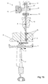
- FIG. 1 a shows a side view of a cross-sectional illustration of a device for setting the gap dimension, with an eccentric mechanism
- FIG. 1 b shows a front view of a vertical sectional illustration of the device shown in FIG. 1 a ,
- FIG. 1 c shows a composite illustration of a top view along a sectional line B—B in FIG. 1 b ,
- FIG. 2 a shows an exemplary embodiment of a device for setting the gap dimension, with direct kinematic coupling between the drive means and the heat accumulation segment,
- FIG. 2 b shows an illustration of a top view relating to the device shown in FIG. 2 a ,
- FIG. 2 c shows an illustration of a detail of the articulation of the drive means on the heat accumulation segment.
- FIG. 1 a shows a sectional view longitudinally to the run of a moving blade 1 which rotates about an axis of rotation R and which is provided inside a turbomachine surrounded by a guide-vane carrier 2 .
- the moving blade 1 illustrated in FIG. 1 a represents one moving blade of a multiplicity of moving blades which are arranged within a moving-blade row of a rotor arrangement, not illustrated in any more detail, having the axis of rotation R.
- a heat accumulation segment 4 which, together with the moving-blade end edge 3 , encloses an intermediate gap 5 .
- the heat accumulation segment 4 which is likewise illustrated as representing a multiplicity of heat accumulation segments arranged opposite the moving-blade tips of a moving-blade row along its entire inner region of rotation, is designed in the form of a cylinder segment, as may be gathered particularly from a comparison of the cross-sectional illustration according to FIG. 1 a and the top view according to FIG. 1 c , which will also be discussed in more detail, and has, in particular, two opposite edges 41 , 42 which issue in two corresponding countercontoured groove runs 61 , 62 .
- the groove runs 61 , 62 are located within the guide-vane carrier 2 or in components of the rotary machine which are connected firmly to the guide-vane carrier 2 .
- the heat accumulation segment 4 has a surface 43 which faces the flow duct 7 conically and which, in axial section, is oriented preferably parallel to the moving-blade end edge 3 inclined obliquely to the axis of rotation R.
- the groove runs 61 and 62 each have a groove depth t which is dimensioned such that the heat accumulation segment 4 is displaceable (see the double-arrow illustration) axially or parallel to the axis of rotation.
- the gap width of the gap 5 can be set, preferably minimized.
- a drive system which is composed of a drive means 8 and of an eccentric unit 9 , serves for the axial displacement of the heat accumulation segment 4 .
- the drive means 8 is designed as a rod-like rotary spindle and projects through the guide-vane carrier 2 into an inner space within the turbomachine, said inner space being delimited by the heat accumulation segment 4 and the guide-vane carrier 2 .
- Attached firmly to the end of the drive means 8 designed as a rod-like rotary spindle is the eccentric unit 9 which projects with a guide pin 91 into a guide slot 10 which is part of the heat accumulation segment 4 .
- the guide slot 10 is of linear design and is arranged perpendicularly to the flow direction (see the bold arrow) through the turbomachine, as may be gathered particularly from the top view according to FIG. 1 c , which will be discussed in more detail.
- the drive means 8 designed as a rod-like rotary spindle is rotated about its axis of rotation D
- the rotational movement is converted via the eccentric unit 9 and the guide pin 91 , owing to the guide slot 10 , into a linear movement by means of which the heat accumulation segment 4 is displaced axially within the groove runs 61 , 62 .
- the heat accumulation segment 4 can be radially spaced from the moving-blade end edge 3 or brought nearer to the latter.
- a spin-tensioned bolt 11 is provided, which prevents the heat accumulation segment 4 from moving in the circumferential direction.
- FIG. 1 b shows a further sectional illustration through the exemplary embodiment already illustrated in FIG. 1 a .
- the sectional illustration in FIG. 1 b corresponds to the section along the sectional line A—A which is plotted in FIG. 1 a.
- the moving blade 1 according to FIG. 1 b is illustrated in the flow direction (directed into the drawing plane).
- the heat accumulation segment 4 which is connected via the eccentric unit 9 to the drive means 8 designed as a rod-like rotary spindle.
- the drive means 8 in this case projects through the guide-vane carrier 2 , in which the drive means 8 is guided in two separate sleeve-type ball-bearings 12 .
- the drive means 8 projects through the turbine casing 13 which surrounds the entire turbomachine, including the guide-vane carrier 2 .
- a drive unit 14 and an overload unit 15 are kinematically coupled to the drive means 8 .
- the drive unit 14 consists of an adjusting ring 16 , of a rack segment 17 and of a gearwheel 18 which projects into the rack segment 17 and which is firmly connected to the drive means 8 .
- a fixed counterstop 19 against which is prestressed a spring 20 which, in turn, presses in a force-induced manner against the gearwheel 18 , ensures, in conjunction with the overload unit 15 designed as an overload clutch, that the drive means 8 is driven with a limited torque.
- the heat accumulation segment 4 is displaced axially due to the rotation of the drive means 8 , with the result that the gap 5 can be reduced specifically. If force-induced contact occurs between the heat accumulation segment 4 and the moving-blade end edge 3 , the rubbing causes a force to be transmitted to the heat accumulation segment 4 , the eccentric unit 9 and the overload unit 15 . In this case, the overload clutch 15 slips, thus ensuring that no serious damage can occur as a result of the rubbing of the moving-blade tip against the heat accumulation segment.
- every single drive means 8 may be actuated individually.
- the individual drive means 8 may also be coupled mechanically to one another in such a way that an overriding regulating mechanism jointly positions the multiplicity of individual heat accumulation segments.
- FIG. 1 a the sectional line C—C is shown along which the sectional diagram according to FIG. 1 c is obtained.
- This is, in particular, a top view of the heat accumulation segment 4 which projects on both sides, along its two edges 41 , 42 , into the groove runs 61 , 62 of a guide-vane carrier 2 .
- the double-arrow illustration above and below the heat accumulation segment indicates the axial displaceability within the groove run 61 .
- a moving blade 1 which stands on a platform in the root region, is illustrated with a corresponding direction of movement.
- the rotary spindle of the drive means 8 is illustrated in a top view and is connected via the eccentric unit 9 to the guide pin 91 which projects into the guide groove 10 of the heat accumulation segment 4 .
- the spring-loaded bolt 11 secures the heat accumulation segment 4 against slipping out of place in the circumferential direction.
- FIG. 2 a shows an illustration corresponding to the sectional illustration according to FIG. 1 a , but with an alternative solution for the kinematic articulation of the heat accumulation segment 4 .
- the heat accumulation segment 4 again, has a conically designed inner contour 43 which is designed coparallel with the likewise obliquely formed moving-blade crown 3 .
- corresponding edge portions 41 , 42 of the heat accumulation segment 4 issue into groove runs 61 , 62 within the guide-vane carrier.
- the groove runs 61 , 62 have a pitch running perpendicularly to the drawing plane according to FIG.
- the drive means 8 is designed as a rod which projects through the guide-vane carrier 2 obliquely to the direction of rotation. This may be gathered, in particular, from the illustration of the top view according to FIG. 2 b and FIG. 2 c .
- the drive means 8 is connected fixedly in terms of rotation about an axis via a bolt connection 21 .
- the connection has sufficient play, so that the drive means 8 can be displaced axially in relation to the heat accumulation segment.
- the bolt of the bolt connection 21 issues in a sliding or ball-bearing which ensures relative moveability in relation to the heat accumulation segment.
- the heat accumulation segment 4 is moved by the drive means 8 designed as a drive rod, it executes a combined movement in the circumferential direction and in the axial direction.
- the gap between the moving blade 1 and the heat accumulation segment 4 is thus set.
- an overload clutch and a mechanical drive system may be provided on the drive rod 8 outside the turbine casing, not illustrated in any more detail, as is illustrated especially in conjunction with the exemplary embodiment according to FIG. 1 .
Landscapes
- Engineering & Computer Science (AREA)
- Mechanical Engineering (AREA)
- General Engineering & Computer Science (AREA)
- Turbine Rotor Nozzle Sealing (AREA)
- Structures Of Non-Positive Displacement Pumps (AREA)
Abstract
Description
Claims (16)
Applications Claiming Priority (3)
| Application Number | Priority Date | Filing Date | Title |
|---|---|---|---|
| DE10060740A DE10060740A1 (en) | 2000-12-07 | 2000-12-07 | Device for setting gap dimensions for a turbomachine |
| DE10060740.3 | 2000-12-07 | ||
| DE10060740 | 2000-12-07 |
Publications (2)
| Publication Number | Publication Date |
|---|---|
| US20020071763A1 US20020071763A1 (en) | 2002-06-13 |
| US6672831B2 true US6672831B2 (en) | 2004-01-06 |
Family
ID=7666080
Family Applications (1)
| Application Number | Title | Priority Date | Filing Date |
|---|---|---|---|
| US09/995,583 Expired - Fee Related US6672831B2 (en) | 2000-12-07 | 2001-11-29 | Device for setting the gap dimension for a turbomachine |
Country Status (3)
| Country | Link |
|---|---|
| US (1) | US6672831B2 (en) |
| DE (1) | DE10060740A1 (en) |
| GB (1) | GB2371093B (en) |
Cited By (17)
| Publication number | Priority date | Publication date | Assignee | Title |
|---|---|---|---|---|
| US20040151582A1 (en) * | 2002-08-03 | 2004-08-05 | Faulkner Andrew Rowell | Sealing of turbomachinery casing segments |
| US20060133927A1 (en) * | 2004-12-16 | 2006-06-22 | Siemens Westinghouse Power Corporation | Gap control system for turbine engines |
| US20080008574A1 (en) * | 2006-07-07 | 2008-01-10 | Siemens Power Generation, Inc. | Leakage flow control and seal wear minimization system for a turbine engine |
| US20080063513A1 (en) * | 2006-09-08 | 2008-03-13 | Siemens Power Generation, Inc. | Turbine blade tip gap reduction system for a turbine engine |
| US20080131270A1 (en) * | 2006-12-04 | 2008-06-05 | Siemens Power Generation, Inc. | Blade clearance system for a turbine engine |
| US20100162722A1 (en) * | 2006-12-15 | 2010-07-01 | Siemens Power Generation, Inc. | Tip clearance control |
| US20100183426A1 (en) * | 2009-01-19 | 2010-07-22 | George Liang | Fluidic rim seal system for turbine engines |
| US20100196139A1 (en) * | 2009-02-02 | 2010-08-05 | Beeck Alexander R | Leakage flow minimization system for a turbine engine |
| US20110280712A1 (en) * | 2010-05-12 | 2011-11-17 | Graefe Richard | Passage wall section for an annular flow passage of an axial turbomachine with radial gap adjustment |
| US20140096370A1 (en) * | 2012-10-04 | 2014-04-10 | Giuseppe Lauritano | Device and method for setting vehicle ignition system |
| US9028205B2 (en) | 2012-06-13 | 2015-05-12 | United Technologies Corporation | Variable blade outer air seal |
| US20150167488A1 (en) * | 2013-12-18 | 2015-06-18 | John A. Orosa | Adjustable clearance control system for airfoil tip in gas turbine engine |
| US20160177773A1 (en) * | 2014-12-19 | 2016-06-23 | Schlumberger Technology Corporation | Apparatus for Extending the Flow Range of Turbines |
| US9435218B2 (en) | 2013-07-31 | 2016-09-06 | General Electric Company | Systems relating to axial positioning turbine casings and blade tip clearance in gas turbine engines |
| US9441499B2 (en) | 2013-07-31 | 2016-09-13 | General Electric Company | System and method relating to axial positioning turbine casings and blade tip clearance in gas turbine engines |
| US20160312645A1 (en) * | 2013-12-17 | 2016-10-27 | United Technologies Corporation | Turbomachine blade clearance control system |
| US9587507B2 (en) | 2013-02-23 | 2017-03-07 | Rolls-Royce North American Technologies, Inc. | Blade clearance control for gas turbine engine |
Families Citing this family (12)
| Publication number | Priority date | Publication date | Assignee | Title |
|---|---|---|---|---|
| GB0411850D0 (en) * | 2004-05-27 | 2004-06-30 | Rolls Royce Plc | Spacing arrangement |
| EP1746256A1 (en) * | 2005-07-20 | 2007-01-24 | Siemens Aktiengesellschaft | Reduction of gap loss in turbomachines |
| EP1965036A1 (en) * | 2007-03-02 | 2008-09-03 | Siemens Aktiengesellschaft | Turbomachine with adjustable shroud contour |
| WO2010044139A1 (en) * | 2008-10-14 | 2010-04-22 | 株式会社日立製作所 | Device for detecting defect of turbine rotor blade and method for detecting defect of turbine rotor blade |
| GB0916892D0 (en) * | 2009-09-28 | 2009-11-11 | Rolls Royce Plc | A casing component |
| US9488062B2 (en) * | 2012-05-10 | 2016-11-08 | General Electric Company | Inner turbine shell axial movement |
| US20130315716A1 (en) * | 2012-05-22 | 2013-11-28 | General Electric Company | Turbomachine having clearance control capability and system therefor |
| CN103511003B (en) * | 2012-06-28 | 2015-12-16 | 中航商用航空发动机有限责任公司 | Control system |
| PL232314B1 (en) | 2016-05-06 | 2019-06-28 | Gen Electric | Fluid-flow machine equipped with the clearance adjustment system |
| KR102316629B1 (en) * | 2020-06-23 | 2021-10-25 | 두산중공업 주식회사 | Turbine blade tip clearance control apparatus and gas turbine comprising the same |
| US11746670B2 (en) * | 2021-12-27 | 2023-09-05 | Pratt & Whitney Canada Corp. | Impeller shroud assembly and method for operating same |
| US12421863B2 (en) * | 2023-07-21 | 2025-09-23 | Rtx Corporation | Turbine engine tip clearance control system with thrust bearing |
Citations (6)
| Publication number | Priority date | Publication date | Assignee | Title |
|---|---|---|---|---|
| DE1178253B (en) | 1962-03-03 | 1964-09-17 | Maschf Augsburg Nuernberg Ag | Axial flow impeller machine with adjustable shroud |
| US3520635A (en) * | 1968-11-04 | 1970-07-14 | Avco Corp | Turbomachine shroud assembly |
| US4330234A (en) | 1979-02-20 | 1982-05-18 | Rolls-Royce Limited | Rotor tip clearance control apparatus for a gas turbine engine |
| US4332523A (en) * | 1979-05-25 | 1982-06-01 | Teledyne Industries, Inc. | Turbine shroud assembly |
| US4863345A (en) | 1987-07-01 | 1989-09-05 | Rolls-Royce Plc | Turbine blade shroud structure |
| US5228828A (en) | 1991-02-15 | 1993-07-20 | General Electric Company | Gas turbine engine clearance control apparatus |
-
2000
- 2000-12-07 DE DE10060740A patent/DE10060740A1/en not_active Withdrawn
-
2001
- 2001-11-29 US US09/995,583 patent/US6672831B2/en not_active Expired - Fee Related
- 2001-11-30 GB GB0128795A patent/GB2371093B/en not_active Expired - Fee Related
Patent Citations (6)
| Publication number | Priority date | Publication date | Assignee | Title |
|---|---|---|---|---|
| DE1178253B (en) | 1962-03-03 | 1964-09-17 | Maschf Augsburg Nuernberg Ag | Axial flow impeller machine with adjustable shroud |
| US3520635A (en) * | 1968-11-04 | 1970-07-14 | Avco Corp | Turbomachine shroud assembly |
| US4330234A (en) | 1979-02-20 | 1982-05-18 | Rolls-Royce Limited | Rotor tip clearance control apparatus for a gas turbine engine |
| US4332523A (en) * | 1979-05-25 | 1982-06-01 | Teledyne Industries, Inc. | Turbine shroud assembly |
| US4863345A (en) | 1987-07-01 | 1989-09-05 | Rolls-Royce Plc | Turbine blade shroud structure |
| US5228828A (en) | 1991-02-15 | 1993-07-20 | General Electric Company | Gas turbine engine clearance control apparatus |
Cited By (26)
| Publication number | Priority date | Publication date | Assignee | Title |
|---|---|---|---|---|
| US20040151582A1 (en) * | 2002-08-03 | 2004-08-05 | Faulkner Andrew Rowell | Sealing of turbomachinery casing segments |
| US6884027B2 (en) * | 2002-08-03 | 2005-04-26 | Alstom Technology Ltd. | Sealing of turbomachinery casing segments |
| US20060133927A1 (en) * | 2004-12-16 | 2006-06-22 | Siemens Westinghouse Power Corporation | Gap control system for turbine engines |
| US7234918B2 (en) | 2004-12-16 | 2007-06-26 | Siemens Power Generation, Inc. | Gap control system for turbine engines |
| US20080008574A1 (en) * | 2006-07-07 | 2008-01-10 | Siemens Power Generation, Inc. | Leakage flow control and seal wear minimization system for a turbine engine |
| US7549835B2 (en) | 2006-07-07 | 2009-06-23 | Siemens Energy, Inc. | Leakage flow control and seal wear minimization system for a turbine engine |
| US20080063513A1 (en) * | 2006-09-08 | 2008-03-13 | Siemens Power Generation, Inc. | Turbine blade tip gap reduction system for a turbine engine |
| US20080131270A1 (en) * | 2006-12-04 | 2008-06-05 | Siemens Power Generation, Inc. | Blade clearance system for a turbine engine |
| US7686569B2 (en) * | 2006-12-04 | 2010-03-30 | Siemens Energy, Inc. | Blade clearance system for a turbine engine |
| US7785063B2 (en) | 2006-12-15 | 2010-08-31 | Siemens Energy, Inc. | Tip clearance control |
| US20100162722A1 (en) * | 2006-12-15 | 2010-07-01 | Siemens Power Generation, Inc. | Tip clearance control |
| US8277177B2 (en) | 2009-01-19 | 2012-10-02 | Siemens Energy, Inc. | Fluidic rim seal system for turbine engines |
| US20100183426A1 (en) * | 2009-01-19 | 2010-07-22 | George Liang | Fluidic rim seal system for turbine engines |
| US20100196139A1 (en) * | 2009-02-02 | 2010-08-05 | Beeck Alexander R | Leakage flow minimization system for a turbine engine |
| US20110280712A1 (en) * | 2010-05-12 | 2011-11-17 | Graefe Richard | Passage wall section for an annular flow passage of an axial turbomachine with radial gap adjustment |
| US8721270B2 (en) * | 2010-05-12 | 2014-05-13 | Siemens Aktiengesellschaft | Passage wall section for an annular flow passage of an axial turbomachine with radial gap adjustment |
| US9028205B2 (en) | 2012-06-13 | 2015-05-12 | United Technologies Corporation | Variable blade outer air seal |
| US20140096370A1 (en) * | 2012-10-04 | 2014-04-10 | Giuseppe Lauritano | Device and method for setting vehicle ignition system |
| US9587507B2 (en) | 2013-02-23 | 2017-03-07 | Rolls-Royce North American Technologies, Inc. | Blade clearance control for gas turbine engine |
| US9441499B2 (en) | 2013-07-31 | 2016-09-13 | General Electric Company | System and method relating to axial positioning turbine casings and blade tip clearance in gas turbine engines |
| US9435218B2 (en) | 2013-07-31 | 2016-09-06 | General Electric Company | Systems relating to axial positioning turbine casings and blade tip clearance in gas turbine engines |
| US20160312645A1 (en) * | 2013-12-17 | 2016-10-27 | United Technologies Corporation | Turbomachine blade clearance control system |
| US10364694B2 (en) * | 2013-12-17 | 2019-07-30 | United Technologies Corporation | Turbomachine blade clearance control system |
| US20150167488A1 (en) * | 2013-12-18 | 2015-06-18 | John A. Orosa | Adjustable clearance control system for airfoil tip in gas turbine engine |
| US20160177773A1 (en) * | 2014-12-19 | 2016-06-23 | Schlumberger Technology Corporation | Apparatus for Extending the Flow Range of Turbines |
| US9840933B2 (en) * | 2014-12-19 | 2017-12-12 | Schlumberger Technology Corporation | Apparatus for extending the flow range of turbines |
Also Published As
| Publication number | Publication date |
|---|---|
| GB2371093A (en) | 2002-07-17 |
| DE10060740A1 (en) | 2002-06-13 |
| US20020071763A1 (en) | 2002-06-13 |
| GB0128795D0 (en) | 2002-01-23 |
| GB2371093B (en) | 2004-12-01 |
Similar Documents
| Publication | Publication Date | Title |
|---|---|---|
| US6672831B2 (en) | Device for setting the gap dimension for a turbomachine | |
| US6406256B1 (en) | Device and method for the controlled setting of the gap between the stator arrangement and rotor arrangement of a turbomachine | |
| US7909566B1 (en) | Rotor thrust balance activated tip clearance control system | |
| US20020009361A1 (en) | Shaft bearing for a turbomachine, turbomachine, and method of operating a turbomachine | |
| EP2395200B1 (en) | Gas turbine engine blade mounting arrangement | |
| US5993152A (en) | Nonlinear vane actuation | |
| EP1676978B1 (en) | Gas turbine engine blade tip clearance apparatus and method | |
| US5035573A (en) | Blade tip clearance control apparatus with shroud segment position adjustment by unison ring movement | |
| CA1139231A (en) | Clearance control | |
| EP2886801B1 (en) | Seal system for a gas turbine and corresponding gas turbine | |
| EP2644836B1 (en) | Gas turbine assembly having an effusion cooled shroud segment with an abradable coating | |
| US5215442A (en) | Turbine blade platform damper | |
| US20020150469A1 (en) | Turbine | |
| US6575704B1 (en) | Turbomachine and sealing element for a rotor thereof | |
| US4279572A (en) | Sideplates for rotor disk and rotor blades | |
| WO2015056656A1 (en) | Gas turbine | |
| US20190277149A1 (en) | Turbine apparatus | |
| CN113107615B (en) | Active clearance control labyrinth seal structure based on eccentric damping action | |
| EP2971570A1 (en) | Fan blade dovetail and spacer | |
| US4688992A (en) | Blade platform | |
| EP4223988B1 (en) | Compressor with reduced vane tip clearance | |
| US7140832B2 (en) | Method and system for rotating a turbine stator ring | |
| US20100014960A1 (en) | Gas-turbine engine with variable stator vanes | |
| EP3929404B1 (en) | Apparatus for controlling turbine blade tip clearance and gas turbine including the same | |
| CN112983564B (en) | A steam turbine steam pressure following opening and closing type axial pressure reducing steam seal structure |
Legal Events
| Date | Code | Title | Description |
|---|---|---|---|
| AS | Assignment |
Owner name: ALSTOM POWER N.V., NETHERLANDS Free format text: ASSIGNMENT OF ASSIGNORS INTEREST;ASSIGNORS:BRANDL, HERBERT;BUSEKROS, ARMIN;MARX, PETER;AND OTHERS;REEL/FRAME:012497/0794 Effective date: 20020111 |
|
| AS | Assignment |
Owner name: ALSTOM (SWITZERLAND) LTD, SWITZERLAND Free format text: ASSIGNMENT OF ASSIGNORS INTEREST;ASSIGNOR:ALSTOM POWER N.V.;REEL/FRAME:013931/0878 Effective date: 20030401 |
|
| AS | Assignment |
Owner name: ALSTOM TECHNOLGY LTD, SWITZERLAND Free format text: ASSIGNMENT OF ASSIGNORS INTEREST;ASSIGNOR:ALSTOM (SWITZERLAND) LTD.;REEL/FRAME:015613/0640 Effective date: 20031105 |
|
| FPAY | Fee payment |
Year of fee payment: 4 |
|
| FPAY | Fee payment |
Year of fee payment: 8 |
|
| REMI | Maintenance fee reminder mailed | ||
| LAPS | Lapse for failure to pay maintenance fees | ||
| STCH | Information on status: patent discontinuation |
Free format text: PATENT EXPIRED DUE TO NONPAYMENT OF MAINTENANCE FEES UNDER 37 CFR 1.362 |
|
| STCH | Information on status: patent discontinuation |
Free format text: PATENT EXPIRED DUE TO NONPAYMENT OF MAINTENANCE FEES UNDER 37 CFR 1.362 |
|
| FP | Lapsed due to failure to pay maintenance fee |
Effective date: 20160106 |