US6667442B1 - Electric utility cross arm - Google Patents
Electric utility cross arm Download PDFInfo
- Publication number
- US6667442B1 US6667442B1 US10/205,434 US20543402A US6667442B1 US 6667442 B1 US6667442 B1 US 6667442B1 US 20543402 A US20543402 A US 20543402A US 6667442 B1 US6667442 B1 US 6667442B1
- Authority
- US
- United States
- Prior art keywords
- cross
- arm
- opening
- insulating member
- insulating
- Prior art date
- Legal status (The legal status is an assumption and is not a legal conclusion. Google has not performed a legal analysis and makes no representation as to the accuracy of the status listed.)
- Expired - Fee Related
Links
Images


Classifications
-
- H—ELECTRICITY
- H02—GENERATION; CONVERSION OR DISTRIBUTION OF ELECTRIC POWER
- H02G—INSTALLATION OF ELECTRIC CABLES OR LINES, OR OF COMBINED OPTICAL AND ELECTRIC CABLES OR LINES
- H02G7/00—Overhead installations of electric lines or cables
- H02G7/05—Suspension arrangements or devices for electric cables or lines
- H02G7/053—Suspension clamps and clips for electric overhead lines not suspended to a supporting wire
Definitions
- the present invention concerns electric utility cross-arms made of lightweight insular materials and having the added qualities of high-strength, ease of construction and repair and durability. More particularly the present invention concerns improvements to cross-arms that permit the quick repair and/or upgrading of electrical service components, while providing high-strength and lightweight characteristics, as well as durability that exceeds that of traditional wood cross-arm systems by two to three times.
- Electrical transmission wires require the use of transmission or utility poles that carry the means, typically cross-arms, to permit the electrical transmission wires to be strung from pole to pole so that the electricity can be taken from its point of creation to its point of use.
- power companies, and others have used cross-arms of wood, steel, composite materials and concrete to carry power lines.
- the cross-arms carry electrical insulators often made of glass or other non-conductive material which provide a degree of insulation between the cross-arm and the electrical transmission cables.
- construction methods required that certain insulator be used on certain cross arms for certain situations and conditions. When conditions or situations changed, the cross arms and/or the insulators are required to be changed to accommodate the changes. Often times such changes required that a utility worker climb a utility pole and remove cross arms, insulators and other equipment, using construction techniques that are not easy to do and are particularly not easy to do at the heights that such wires are found.
- U.S. Pat. No. 6,027,082 discloses a convertible electric utility cross-arm insulator.
- the '082 patent discloses a device and method for converting such cross arms so that they can accommodate a number of different types of utility situations.
- the '082 patent further teaches the use of plastic and/or resin cross-arms which provide a lightweight, electrically insulated and durable means of holding electrical transmission wires onto poles and permitting the stringing of transmission wires over great distances.
- the '082 patent discloses means to be able to convert a cross-arm from a single line carrier to a double or triple line carrier.
- the device uses insulating members with threadings, used in association with wire support devices having internal threadings, that permit the support members to be added or removed by screwing or unscrewing the support member from the insulator.
- the cross-arm can be changed, to accommodate different configurations of wires, more quickly than prior art cross-arm members, where the insulator and wire support are more permanently attached to each other.
- U.S. Pat. No. 6,027,082 is incorporated herein, in its entirety, by reference.
- fillers such as lead filled nuts
- the insulator In some cross-arms of the prior art, it has been necessary to use fillers, such as lead filled nuts, as an interference to allow the insulator to be turned and maintained such that the path of the wire on the insulator is perpendicular to the cross-arm.
- the use of such a system to permit the wires to run perpendicular to the cross-arm causes difficulties in alignment during the setup of cable systems and allows for variability in the settings. Further, there is an added element of increased weight and cost in the use of fillers.
- a lightweight electrical utility cross-arm for quick and easy assembly of an electrical transmission member for carrying electrical wires.
- the cross-arm member comprises at least one generally vertical opening for receiving at least one insulating member.
- the cross-arm system further comprises a clip element for holding the insulating member inside of the generally vertical opening in the cross-arm.
- a wire holding member for insertion onto said insulating member is provided to hold an electrical transmission line in place and in a desirable position, generally perpendicular to the plane of the cross-arm. The insulating member being held in place on the insulating member by the weight of an electrical wire.
- the cross-arm member is constructed of a plastic or resin material and is typically created in a molding process.
- a single mold is used and is designed so that tongues and grooves are intermittently created in the moldings.
- the cross-arm is created from two molding pieces (which can be made from the same mold or an identical mold) placed open ends together, such that the tongues and grooves end up opposite each other such that the tongues and grooves fit together to help hold the cross-arm members together.
- the cross-arm tongues are created on one half of each mold and the grooves are created on the other half, such that when the two cross-arm pieces (preferably made from the same mold) are placed facing each other, tongues of one molded piece correspond with grooves of the other molded piece, permitting the pieces to fit together and interlock.
- the cross-arm has a generally diamond shape, adding to the overall strength of the member, and is constructed with generally vertical openings at the top most section of the generally diamond shape and at the two side arms, such that a configuration of one, two or three transmission wires may be made with the cross-arm member.
- insulating rods having a tongue or tab at one end, such that it can fit into a groove or slot in the cross-arm, are provided.
- the tab is specifically designed to assure correct wire-groove rotation and orientation.
- the insulating rods further comprise notches near their bottom ends, such that a cotter-type spring pin, “C” or “U” style clip, may be placed onto the notches to keep the insulating rod in place.
- the notches are generally horizontal and the clip are typically “C” or “U” shaped clip.
- the cross-arm of the present invention defines a slot; located adjacent to the generally vertical cylindrical opening, such that when insulating rod is placed into the generally vertical opening, and the tongue or tab of the insulating member is fitted into the groove or slot in the cross-arm at the base of the generally vertical opening, the cotter-type spring pin may be inserted into the slot in the cross-arm, through the notches in the insulating member, such that the insulating rod is locked into the cross-arm until it is desired that it be removed by pulling the “C” or “U” clip out.
- the “C” or “U” clip of the preferred embodiment of the present invention is typically constructed so that it comprises a generally flat portion having two elongated tines emerging therefrom.
- the tines are designed such that the spring-clip, when engaged, is always under tension so as to prevent its becoming disengaged.
- the clip comprises a series of undulations that permit it to be better locked into place until removal is desired.
- the slot or groove within the generally vertical opening in a preferred embodiment, is constructed such that it ramps downwardly from the center of the slot to the edge, near the outside wall of the cross-arm body proper (forming a generally inverted V-shaped).
- the outside wall of the cross-arm is, further, provided with a weep-hole opening intersecting the slot or groove. In this manner, any water entering the cross-arm through the generally vertical opening, or any other adjacent openings, (by means of precipitation or the like) can be naturally eliminated.
- the slot or groove thereby performs the dual function of permitting the mating of the insulating rods with the cross-arm and as a means to drain any fluids from within the cross-arm body.
- insulating wire holders having a simple cylindrical opening created through the center bottom are used.
- the insulating wire holders are simply slid onto the insulating members to make a simple friction fit, generally held together by the weight of the electrical transmission cable placed thereon.
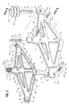
- FIG. 1 is a perspective view of the cross arm of the present invention with insulator pins and a schematic representation of the quick installation method for the insulator pins and members.
- FIG. 2 is a perspective view of the parts of the cross-arm and component parts of FIG. 1, schematically representing the manner of assembly of the device of FIG. 1 .
- FIG. 3 is a perspective view of the front and back sections of the upper support neck of the device of FIG. 2, broken away to show the details of the parts and the manner of their assembly.
- FIG. 4 is a perspective view of the front and back sections of one of the two lateral arm supports of the device of FIG. 2, broken away to show the details of the parts and the manner of assembly.
- FIG. 5 is a cross-sectional view, taken along the plane of line 5 — 5 of FIG. 2, of the wire support member, insulator member and spring clip shown in FIG. 2 .
- FIG. 6 is a top plan view of the wire support member and insulator of FIG. 5 .
- FIG. 7 is a cross-sectional view, taken along the plane of line 7 — 7 of FIG. 5, showing the spring clip of the present invention.
- FIG. 1 shows a perspective view of a cross-arm 10 of the present invention.
- cross-arm 10 comprises a vertical member 12 and a horizontal member 14 , crossing vertical member 12 .
- Cross-arm 10 further comprises an upper support arms 16 and 18 and lower support arms 20 and 22 .
- Cross-arm 10 also comprises a neck support 24 and two arm supports 26 , which will be described in greater detail below.
- Cross-arm 10 further comprises openings 23 , of a type and manner well known in the art, to permit the attachment of cross-arm 10 to a utility pole (not shown).
- cross-arm 10 can be constructed of a number of different materials having characteristics that will provide strength, durability and desirable weight, without departing from the novel scope of the present invention.
- cross-arm 10 is constructed using a molding process, of a type well known in the art, using high strength plastic resins such as thermoset or thermoplastic resins.
- cross-arm 10 is constructed using either blow-molding methods or injection molding methods.
- cross-arm 10 is created in two sections (front section 10 a and rear section 10 b ) that are joined, using means and methods well known in the art, along a seam 10 c .
- cross-arm 10 may be joined together using such means and methods as adhesives or fasteners and welding and other methods, without departing from the novel scope of the present invention.
- neck support 24 and arm supports 26 each define a generally cylindrical opening 30 , into which an insulating member 32 may be placed.
- insulating member 32 comprises an elongated cylinder portion 32 a , a rounded top portion 32 b and an end portion 32 c .
- Member 32 further comprises a longitudinal axis 34 , and a pair of notches 36 defined, diametrically opposed to each other, near end 32 c of member 32 .
- Notches 36 are made such that a thin portion 38 of the diameter of member 32 remains.
- notches 36 are defined diametrically apart from each other at the same position along axis 34 of member 32 .
- Notches 36 are defined such that a “C” or “U” style clip pin 40 of a given thickness 42 can be snuggly held within notches 36 when member 32 is in place, as will be described in greater-detail below.
- Member 32 further defines a reduced cross-section area tab or tongue 37 which rests in slot or groove 31 (FIG. 3, FIG. 4) within openings 30 in cross-arm 10 .
- tab or tongue 37 permits the easy placement of member 32 within opening 30 such that notches 36 lineup with slots 44 . While a generally tongue 37 and groove 31 connection is shown, it will be understood by persons having skill in the art that any type of connection, or shape of tongue and slot, permitting member 32 to be aligned in opening 30 in the manner described, can be used without departing from the novel scope of the present invention.
- member 32 is made using an over-molding process. In such a process the formation of member 32 with a rounded end 32 b aids in the production of member 32 . Further, as will be understood by persons having skill in the art, the creation of rounded head 32 b provides for a reduction of hoop stresses on member 32 in its use on cross-arm 10 , in association with a wire holder 50 (the use of wire holder 50 is discussed in greater detail below). It will be understood that a member 32 may be made with a flat head or a head having any desired shape, using materials other than the thermoset and/or thermoplastic materials used in one of the preferred embodiments. Such materials as steel, or other metals, wood or other materials, natural or synthetic, may be used with out departing from the novel scope of the present invention. Such materials will, typically, add weight and increased cost to a cross-arm so constructed.
- an insulating wire holder 50 is provided with a wire rest section 52 , on which a transmission cable 53 may be laid, and sections 54 , which can be conically shaped or disk shaped depending on the application and desires of the user.
- sections 54 are referred to as “watershed rings”. It will be understood by persons having skill in the art that wire holder 60 may be of any variety of types and shapes presently available or of a type and shape having similar characteristics without departing from the novel scope of the present invention.
- Wire holder 50 provides a means to hold a cable 53 in position on cross-arm 10 while insulating the wire from any metal or other conducting elements. While prior art wire holders typically required that the wire holder include a manner of attachment to a holding member (such as member 30 ) such as interior threadings to cooperate with exterior threadings of insulating member, wire holder 50 of the present invention is constructed solely with a cylindrical shaped opening 51 formed within. In the operation of the device of the present invention, member 32 is inserted into one opening 30 of cross-arm 10 and wire holder 50 is simply placed thereon. It will be seen that wire holder 50 is held in place, on member 32 , by the weight and positioning of cable 52 . Construction and repair is thereby facilitated by the friction-only fit of the various components of the device of the present invention, rather than requiring that the various components be fastened together by various means, including threadings.
- clip 40 can include interference detents 40 a and 40 b so as to provide extra, or redundant, retention means.
- elements 10 a and 10 b of cross-arm 10 are identical in form. In this manner the number of parts is reduced and the difficulty of identify parts for assembly is removed.
- both elements 10 a and 10 b are constructed using identical molds.
- the interior space 10 e of cross-arm 10 is formed such that a substantial interior area 10 f is hollowed-out and the edges 10 g , which are substantially perpendicular to the walls 10 h of cross-arm 10 , form structural elements in the form of a lattice structure.
- the use of structural elements 10 g along with hollowed-out sections 10 e provides a lightweight yet substantially strengthened cross-arm 10 .
- tongues 60 and connector grooves 62 are molded into elements 10 a and 10 b of cross-arm 10 .
- the inclusion of tongue and groove parts on elements 10 a and 10 b permits the joinder of these identically molded elements. When the elements are removed from their molds and made to face one another, the tongues of one element will be aligned with the grooves of the other element allowing the units to be joined together.
- the creation of tongues 60 and grooves 62 permits the parts of cross-arm 10 to be placed such that the seal between the two parts is generally in a compression mode, providing greater strength and durability of the system.
- cross-arm 10 It will be understood by persons having skill in the art that use of adhesives or fasteners, or other means, manner or methods, to maintain the joinder of element is a desired next step in the construction of cross-arm 10 . It will be further understood by persons having skill in the art that elements 10 a and 10 b of cross-arm 10 can, instead be created as a single molded element, in for example a blow-mold form, eliminating the need to assemble the cross-arm after molding, without departing from the novel scope of the present invention.
- groove 31 is constructed such that the interior end 31 i of groove 31 is slightly elevated in comparison with the exterior end 31 e of groove 31 (that is, the groove ramps down from the center of cross-arm 10 to the outside walls of cross-arm 10 ). Further a weep hole or opening 31 a is defined in cross-arm elements 10 a and 10 b , adjacent to groove exterior end 31 e , such that groove 31 is in connection with opening 31 a . In this manner, during the use of the device of the present invention, any water (such as rain or other precipitation) entering cross-arm 31 through openings 30 or 44 can be eliminated from the interior of cross-arm 10 through opening 31 a . In another preferred embodiment, further openings 31 f are included to provide additional drainage at lower levels of cross-arm 10 . The additional openings 31 f function as a redundant fail-safe permitting water to be shed through the bond flange 70 .
- neck support 24 and arm supports 26 are shown in greater detail. It will be seen that, as in the other sections of cross-arm 10 , tongue 60 and groove 62 moldings have been created in the moldings of the various sections, providing for the quick and easy assembly of cross-arm 10 . Further, as a result of the use of identical molds to create both elements 10 a and 10 b , slots 44 are seen to be formed in both sections 10 a and 10 b of cross-arm 10 . While this configuration causes an extra slot 44 to be created in cross-arm 10 sections, it permits the fitting of spring clip 40 into either side of cross-arm 10 , aiding in the quick construction and/or repair of cross-arm 10 . As a result of slots 44 being on both sides, the repair/construction personnel can climb the utility pole on either side of cross-arm 10 to work on the device of the present invention.
Landscapes
- Clamps And Clips (AREA)
Abstract
Description
Claims (22)
Priority Applications (1)
| Application Number | Priority Date | Filing Date | Title |
|---|---|---|---|
| US10/205,434 US6667442B1 (en) | 2002-07-25 | 2002-07-25 | Electric utility cross arm |
Applications Claiming Priority (1)
| Application Number | Priority Date | Filing Date | Title |
|---|---|---|---|
| US10/205,434 US6667442B1 (en) | 2002-07-25 | 2002-07-25 | Electric utility cross arm |
Publications (1)
| Publication Number | Publication Date |
|---|---|
| US6667442B1 true US6667442B1 (en) | 2003-12-23 |
Family
ID=29735412
Family Applications (1)
| Application Number | Title | Priority Date | Filing Date |
|---|---|---|---|
| US10/205,434 Expired - Fee Related US6667442B1 (en) | 2002-07-25 | 2002-07-25 | Electric utility cross arm |
Country Status (1)
| Country | Link |
|---|---|
| US (1) | US6667442B1 (en) |
Cited By (14)
| Publication number | Priority date | Publication date | Assignee | Title |
|---|---|---|---|---|
| WO2006014099A1 (en) * | 2004-08-03 | 2006-02-09 | Lau Lay Jesus Francisco | Die for electrically conductive line insulator pin |
| WO2007070966A3 (en) * | 2005-12-23 | 2007-09-07 | Preformed Line Products Austra | Improved utility cross-arm |
| US20120255920A1 (en) * | 2011-04-11 | 2012-10-11 | Abb Technology Ag | Electrical equipment mounting frame |
| USD706203S1 (en) | 2012-03-20 | 2014-06-03 | Wald Llc | Bracket |
| USD722003S1 (en) | 2012-03-20 | 2015-02-03 | Wald Llc | Swivel bracket |
| US20170063068A1 (en) * | 2015-08-27 | 2017-03-02 | Austin Cary Bennett | Resilient cross arm assembly |
| USD822604S1 (en) * | 2015-07-30 | 2018-07-10 | Gallagher Group Limited | Insulator |
| US10186850B1 (en) | 2017-10-02 | 2019-01-22 | Electrical Materials Company | Non-metallic electrical cable support arrangement |
| USD839827S1 (en) | 2015-10-22 | 2019-02-05 | Gallagher Group Limited | Insulator |
| US10355467B1 (en) * | 2017-12-28 | 2019-07-16 | Ppl Corporation | Systems and methods for attachment of multiple utility conductors using a megavang |
| USD894125S1 (en) | 2019-05-20 | 2020-08-25 | Electrical Materials Company | Insulator pin for overhead electrical lines |
| USD905641S1 (en) * | 2019-05-15 | 2020-12-22 | Dare Products, Incorporated | Insulator for an electric fence |
| US11004579B2 (en) | 2019-05-20 | 2021-05-11 | Electrical Materials Company | Breakaway pin for overhead electrical lines |
| US11075024B2 (en) | 2015-09-14 | 2021-07-27 | Gallagher Group Limited | Electric fence insulator |
Citations (13)
| Publication number | Priority date | Publication date | Assignee | Title |
|---|---|---|---|---|
| US1149282A (en) * | 1914-05-04 | 1915-08-10 | Charles L Peirce Jr | Insulator-supporting fixture. |
| US1239142A (en) * | 1915-12-15 | 1917-09-04 | Associated Engineers Company | Cross-arm. |
| US3217086A (en) * | 1963-10-07 | 1965-11-09 | Ohio Brass Co | Suspension apparatus with lateral conductor movement for transmission line conductors |
| US3803345A (en) * | 1973-03-12 | 1974-04-09 | E Spaeth | Crossarm |
| US4682747A (en) * | 1986-04-24 | 1987-07-28 | King Jr Halm C | Utility insulated cross-arm |
| US4940857A (en) * | 1989-08-15 | 1990-07-10 | Giroux Pierre R | Insulator for overhead electric wires |
| US5772158A (en) * | 1996-12-02 | 1998-06-30 | Blanding; Douglas | Apparatus for laterally offsetting power lines from utility poles |
| US5945636A (en) * | 1996-04-22 | 1999-08-31 | Hubbell Incorporated | Electrical insulators with mechanical core and dielectric sheath |
| US5981879A (en) * | 1997-10-17 | 1999-11-09 | New Line Products, Llc | Insulating support device for electrical conductor |
| US6027082A (en) | 1998-11-03 | 2000-02-22 | Cai Unit, Inc. | Convertible electric utility cross arm insulator unit |
| US6229086B1 (en) * | 1999-03-12 | 2001-05-08 | Douglas Blanding | Adapter for mounting multiple circuits to utility poles with a pair of cross-arms using candlestick holders |
| US6347488B1 (en) * | 1999-06-29 | 2002-02-19 | Jeffrey T. Koye | Utility pole cross-arm |
| US6555999B1 (en) * | 1999-04-02 | 2003-04-29 | Lindsey Manufacturing Company | Insulator support current sensor |
-
2002
- 2002-07-25 US US10/205,434 patent/US6667442B1/en not_active Expired - Fee Related
Patent Citations (13)
| Publication number | Priority date | Publication date | Assignee | Title |
|---|---|---|---|---|
| US1149282A (en) * | 1914-05-04 | 1915-08-10 | Charles L Peirce Jr | Insulator-supporting fixture. |
| US1239142A (en) * | 1915-12-15 | 1917-09-04 | Associated Engineers Company | Cross-arm. |
| US3217086A (en) * | 1963-10-07 | 1965-11-09 | Ohio Brass Co | Suspension apparatus with lateral conductor movement for transmission line conductors |
| US3803345A (en) * | 1973-03-12 | 1974-04-09 | E Spaeth | Crossarm |
| US4682747A (en) * | 1986-04-24 | 1987-07-28 | King Jr Halm C | Utility insulated cross-arm |
| US4940857A (en) * | 1989-08-15 | 1990-07-10 | Giroux Pierre R | Insulator for overhead electric wires |
| US5945636A (en) * | 1996-04-22 | 1999-08-31 | Hubbell Incorporated | Electrical insulators with mechanical core and dielectric sheath |
| US5772158A (en) * | 1996-12-02 | 1998-06-30 | Blanding; Douglas | Apparatus for laterally offsetting power lines from utility poles |
| US5981879A (en) * | 1997-10-17 | 1999-11-09 | New Line Products, Llc | Insulating support device for electrical conductor |
| US6027082A (en) | 1998-11-03 | 2000-02-22 | Cai Unit, Inc. | Convertible electric utility cross arm insulator unit |
| US6229086B1 (en) * | 1999-03-12 | 2001-05-08 | Douglas Blanding | Adapter for mounting multiple circuits to utility poles with a pair of cross-arms using candlestick holders |
| US6555999B1 (en) * | 1999-04-02 | 2003-04-29 | Lindsey Manufacturing Company | Insulator support current sensor |
| US6347488B1 (en) * | 1999-06-29 | 2002-02-19 | Jeffrey T. Koye | Utility pole cross-arm |
Cited By (18)
| Publication number | Priority date | Publication date | Assignee | Title |
|---|---|---|---|---|
| WO2006014099A1 (en) * | 2004-08-03 | 2006-02-09 | Lau Lay Jesus Francisco | Die for electrically conductive line insulator pin |
| WO2007070966A3 (en) * | 2005-12-23 | 2007-09-07 | Preformed Line Products Austra | Improved utility cross-arm |
| US20120255920A1 (en) * | 2011-04-11 | 2012-10-11 | Abb Technology Ag | Electrical equipment mounting frame |
| US8919584B2 (en) * | 2011-04-11 | 2014-12-30 | Abb Technology Ag | Electrical equipment mounting frame |
| USD706203S1 (en) | 2012-03-20 | 2014-06-03 | Wald Llc | Bracket |
| USD722003S1 (en) | 2012-03-20 | 2015-02-03 | Wald Llc | Swivel bracket |
| USD822604S1 (en) * | 2015-07-30 | 2018-07-10 | Gallagher Group Limited | Insulator |
| US9850677B2 (en) * | 2015-08-27 | 2017-12-26 | Austin Cary Bennett | Resilient cross arm assembly |
| US9784408B2 (en) * | 2015-08-27 | 2017-10-10 | Austin Cary Bennett | Resilient cross arm assembly |
| US9859700B2 (en) * | 2015-08-27 | 2018-01-02 | Austin Cary Bennett | Resilient cross arm assembly |
| US20170063068A1 (en) * | 2015-08-27 | 2017-03-02 | Austin Cary Bennett | Resilient cross arm assembly |
| US11075024B2 (en) | 2015-09-14 | 2021-07-27 | Gallagher Group Limited | Electric fence insulator |
| USD839827S1 (en) | 2015-10-22 | 2019-02-05 | Gallagher Group Limited | Insulator |
| US10186850B1 (en) | 2017-10-02 | 2019-01-22 | Electrical Materials Company | Non-metallic electrical cable support arrangement |
| US10355467B1 (en) * | 2017-12-28 | 2019-07-16 | Ppl Corporation | Systems and methods for attachment of multiple utility conductors using a megavang |
| USD905641S1 (en) * | 2019-05-15 | 2020-12-22 | Dare Products, Incorporated | Insulator for an electric fence |
| USD894125S1 (en) | 2019-05-20 | 2020-08-25 | Electrical Materials Company | Insulator pin for overhead electrical lines |
| US11004579B2 (en) | 2019-05-20 | 2021-05-11 | Electrical Materials Company | Breakaway pin for overhead electrical lines |
Similar Documents
| Publication | Publication Date | Title |
|---|---|---|
| US6667442B1 (en) | Electric utility cross arm | |
| EP2467915B1 (en) | Support towers, insulating cross-arms and insulating members for high voltage power networks | |
| US4818822A (en) | Junction box | |
| KR101564300B1 (en) | Suspension insulator for power transmission and distribution pylon | |
| US6834469B2 (en) | Utility line support member | |
| KR101131082B1 (en) | A fixing body of a power line tower | |
| KR102073865B1 (en) | Crossarm device for stable support of overhead distribution lines | |
| KR20170065022A (en) | Volt Binding Type Linepost Insulator | |
| US3803345A (en) | Crossarm | |
| KR101255117B1 (en) | Racks with insulator for low voltage distribution | |
| KR20170042199A (en) | Line post insulator | |
| KR101793024B1 (en) | Connection insulator for overhead special voltage electric power distribution line | |
| KR101193025B1 (en) | Power transmission and distribution cable for insulator preventing break away | |
| US3908964A (en) | Electric fence | |
| KR101154493B1 (en) | Supporter for low voltage air branch | |
| KR101234259B1 (en) | Suspension insulator for power transmission and distribution pylon | |
| US9362028B2 (en) | Combination insulator cover | |
| WO2009049376A1 (en) | Power line supporting apparatus | |
| AU610537B2 (en) | Improvements relating to wire supports | |
| KR102520150B1 (en) | Tree sculpture for having elastic branch | |
| US20070107929A1 (en) | Insulator integrated with clamp | |
| CN210575298U (en) | Column type porcelain insulator with bird damage prevention structure safety cover | |
| CN105952242A (en) | Cross arm and power transmission pole | |
| CN205822907U (en) | Cross arm and transmission pole | |
| US3115543A (en) | Louvered multi-skirt train high voltage suspension insulator |
Legal Events
| Date | Code | Title | Description |
|---|---|---|---|
| AS | Assignment |
Owner name: VENTURE INDUSTRIES, MICHIGAN Free format text: ASSIGNMENT OF ASSIGNORS INTEREST;ASSIGNOR:HILLIGOSS, LLOYD;REEL/FRAME:013154/0470 Effective date: 20020717 |
|
| AS | Assignment |
Owner name: BANK ONE, NA, MICHIGAN Free format text: SECURITY INTEREST;ASSIGNOR:PATENT HOLDING COMPANY;REEL/FRAME:013552/0493 Effective date: 20021021 |
|
| AS | Assignment |
Owner name: BLACK DIAMOND COMMERICAL FINANCE, LLC, C/O BLACK D Free format text: SECURITY INTEREST;ASSIGNOR:PATENT HOLDING COMPANY;REEL/FRAME:014327/0001 Effective date: 20040107 |
|
| CC | Certificate of correction | ||
| AS | Assignment |
Owner name: NEW VENTURE HOLDINGS, LLC, MICHIGAN Free format text: ASSIGNMENT OF ASSIGNORS INTEREST;ASSIGNORS:DELUXE PATTERN CORPORATION;FARM & COUNTRY REAL ESTATE COMPANY;PATENT HOLDING COMPANY;AND OTHERS;REEL/FRAME:016610/0200 Effective date: 20050502 |
|
| AS | Assignment |
Owner name: CADENCE INNOVATION LLC, MICHIGAN Free format text: CHANGE OF NAME;ASSIGNOR:NEW VENTURE HOLDINGS, LLC;REEL/FRAME:017575/0145 Effective date: 20051014 |
|
| AS | Assignment |
Owner name: BANK OF AMERICA, N.A., CALIFORNIA Free format text: SECURITY AGREEMENT;ASSIGNOR:NEW VENTURE HOLDINGS, LLC;REEL/FRAME:017946/0365 Effective date: 20050502 |
|
| FPAY | Fee payment |
Year of fee payment: 4 |
|
| REMI | Maintenance fee reminder mailed | ||
| LAPS | Lapse for failure to pay maintenance fees | ||
| STCH | Information on status: patent discontinuation |
Free format text: PATENT EXPIRED DUE TO NONPAYMENT OF MAINTENANCE FEES UNDER 37 CFR 1.362 |
|
| FP | Expired due to failure to pay maintenance fee |
Effective date: 20111223 |
|
| AS | Assignment |
Owner name: GLOBAL IP HOLDINGS LLC, MICHIGAN Free format text: ASSIGNMENT OF ASSIGNORS INTEREST;ASSIGNOR:CADENCE INNOVATION LLC;REEL/FRAME:033300/0707 Effective date: 20131206 |