US6666794B2 - Apparatus and method for controlling automatic transmission - Google Patents
Apparatus and method for controlling automatic transmission Download PDFInfo
- Publication number
- US6666794B2 US6666794B2 US09/945,705 US94570501A US6666794B2 US 6666794 B2 US6666794 B2 US 6666794B2 US 94570501 A US94570501 A US 94570501A US 6666794 B2 US6666794 B2 US 6666794B2
- Authority
- US
- United States
- Prior art keywords
- back pressure
- controlling
- friction engagement
- pressure
- automatic transmission
- Prior art date
- Legal status (The legal status is an assumption and is not a legal conclusion. Google has not performed a legal analysis and makes no representation as to the accuracy of the status listed.)
- Expired - Fee Related
Links
Images


Classifications
-
- F—MECHANICAL ENGINEERING; LIGHTING; HEATING; WEAPONS; BLASTING
- F16—ENGINEERING ELEMENTS AND UNITS; GENERAL MEASURES FOR PRODUCING AND MAINTAINING EFFECTIVE FUNCTIONING OF MACHINES OR INSTALLATIONS; THERMAL INSULATION IN GENERAL
- F16H—GEARING
- F16H61/00—Control functions within control units of change-speed- or reversing-gearings for conveying rotary motion ; Control of exclusively fluid gearing, friction gearing, gearings with endless flexible members or other particular types of gearing
- F16H61/04—Smoothing ratio shift
- F16H61/06—Smoothing ratio shift by controlling rate of change of fluid pressure
- F16H61/061—Smoothing ratio shift by controlling rate of change of fluid pressure using electric control means
-
- F—MECHANICAL ENGINEERING; LIGHTING; HEATING; WEAPONS; BLASTING
- F16—ENGINEERING ELEMENTS AND UNITS; GENERAL MEASURES FOR PRODUCING AND MAINTAINING EFFECTIVE FUNCTIONING OF MACHINES OR INSTALLATIONS; THERMAL INSULATION IN GENERAL
- F16H—GEARING
- F16H61/00—Control functions within control units of change-speed- or reversing-gearings for conveying rotary motion ; Control of exclusively fluid gearing, friction gearing, gearings with endless flexible members or other particular types of gearing
- F16H61/04—Smoothing ratio shift
- F16H2061/0477—Smoothing ratio shift by suppression of excessive engine flare or turbine racing during shift transition
-
- F—MECHANICAL ENGINEERING; LIGHTING; HEATING; WEAPONS; BLASTING
- F16—ENGINEERING ELEMENTS AND UNITS; GENERAL MEASURES FOR PRODUCING AND MAINTAINING EFFECTIVE FUNCTIONING OF MACHINES OR INSTALLATIONS; THERMAL INSULATION IN GENERAL
- F16H—GEARING
- F16H61/00—Control functions within control units of change-speed- or reversing-gearings for conveying rotary motion ; Control of exclusively fluid gearing, friction gearing, gearings with endless flexible members or other particular types of gearing
- F16H61/04—Smoothing ratio shift
- F16H61/06—Smoothing ratio shift by controlling rate of change of fluid pressure
- F16H61/065—Smoothing ratio shift by controlling rate of change of fluid pressure using fluid control means
- F16H61/067—Smoothing ratio shift by controlling rate of change of fluid pressure using fluid control means using an accumulator
Definitions
- the present invention relates to an apparatus for and a method of controlling an automatic transmission, particularly to the technology of restraining a racing during a speed change.
- a rise in oil pressure in an engagement side friction engagement element is detected by a pressure switch and drain timing of oil pressure in a release side friction engagement element is determined based on the detection result.
- an oil pressure of a release side friction engagement element is increased when a slip amount of the release side friction engagement element is a threshold value or above, while the oil pressure is decreased when a variation ratio of the slip amount is 0 or less.
- the speed change performance is likely to deteriorate due to prolongation of speed change period since the racing is conversed by controlling the oil pressure so as to maintain an extremely small slip amount.
- the present invention has an object of stably restraining an occurrence of racing without cost-up and prolongation of a speed change period in an automatic transmission for carrying out a speed change by controlling a back pressure of an accumulator.
- the construction is such that, in an automatic transmission provided with an accumulator disposed in an oil pressure supply pipe in each of friction engagement elements, at least one of the accumulators in the friction engagement element to be engaged and in the friction engagement element to be released, is increased in stepwise in response to a speed change request, when a racing is detected during a speed change.
- FIG. 1 is a system diagram showing a vehicle drive train.
- FIG. 2 is a skeleton diagram showing a transmission mechanism.
- FIG. 3 is a diagram showing a combination of friction engagement elements in each speed change step.
- FIG. 4 is an oil pressure circuit diagram showing a control valve portion.
- FIG. 5 is a diagram showing an ON/OFF combination of solenoids A, B in each speed change step.
- FIG. 6 is a time chart showing control characteristics at up-shift timing of 2-speed ⁇ 3-speed.
- FIG. 7 is a flowchart showing a first embodiment of a control for restraining a racing during a speed change.
- FIG. 8 is a graph showing characteristics of a correction amount of a back pressure.
- FIG. 9 is a flowchart showing a pre-charge control to an engagement side friction engagement element.
- FIG. 10 is a graph showing characteristics of a pre-charging period in the pre-charge control.
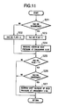
- FIG. 11 is a flowchart showing a second embodiment of the control for restraining a racing during the speed change.
- FIG. 1 shows a vehicle drive train in an embodiment, wherein an output shaft of an engine 101 is connected with an automatic transmission 103 through a torque converter 102 and driving wheels (not shown) of the vehicle are driven for rotation by an output shaft of the automatic transmission 103 .
- Automatic transmission 103 comprises a transmission mechanism portion 103 A and a control valve portion 103 B.
- Control valve portion 103 B is controlled by an A/T controller 104 .
- A/T controller 104 incorporates therein a microcomputer and outputs a control signal to control valve portion 103 B by a calculation process of detection signals from an A/T oil temperature sensor 105 , an accelerator opening sensor 106 , a vehicle speed sensor 107 , a turbine rotation sensor 108 , an engine rotation sensor 109 , an air flow meter 110 and the like.
- FIG. 2 is a skeleton showing transmission mechanism portion 103 A.
- Transmission mechanism portion 103 A includes two sets of planetary gears G 1 , G 2 , three sets of multiple disc clutches (High Clutch H/C, Reverse Clutch R/C, Low Clutch L/C), a set of brake bands 2 & 4 /B, a set of multi plate brakes (low and reverse brakes L & R/B), and a set of one-way clutches L/OWC.
- the two sets of planetary gears G 1 , G 2 are simple planetary gears comprising sun gears S 1 , S 2 , ring gears r 1 , r 2 , and carriers c 1 , c 2 , respectively.
- Sun gear S 1 of planetary gear set G 1 is constructed to be connectable to an input shaft IN by reverse clutch R/C and at the same time, to be fixable by brake bands 2 & 4 /B.
- Sun gear S 2 of planetary gear set G 2 is connected to input shaft IN directly.
- Carrier c 1 of planetary gear set G 1 is constructed to be connectable to input shaft IN by high clutch H/C, while ring gear r 2 of planetary gear set G 2 is constructed to be connectable to carrier c 1 of planetary gear set G 1 by low clutch L/C. Further, carrier c 1 of planetary gear set G 1 constructed to be fixable by low and reverse brake L & R/B.
- Ring gear r 1 of planetary gear set G 1 and carrier c 2 of planetary gear set G 2 are integrally connected to an output shaft OUT.
- forward 1-speed to 4-speed and reverse are realized by a combination of engagement states of each clutch and brake as shown in FIG. 3 .
- a circle mark shows an engagement state and a portion with no mark shows a release state.
- the engagement state of low & reverse brake L & R/B at 1-speed shown in a black circle shows the engagement state only in one range.
- a speed change to replace friction engagement elements by simultaneously controlling engagement and release of clutches and brakes (friction engagement elements) is called as a replacement speed change.
- FIG. 4 shows a detail of control valve portion 103 B.
- control valve portion 103 B shown in FIG. 4 are disposed a shift valve (A) 1 , a shift valve (B), an accumulator control valve 3 for L/C & H/C, an accumulator control valve 4 for 2 & 4 /B, an L/C timing valve (A) 5 , an L/C timing valve (B) 6 , a 2 & 4/B timing valve (A) 7 , a 2 & 4 /B timing valve (B) 8 , an L/C accumulator 9 , a 2 & 4 /B accumulator unit 10 , and an H/C accumulator 11 .
- Shift valve (A) 1 and shift valve (B) 2 perform the switching of oil passage in accordance with a combination of engagement and release corresponding to each speed change step of 1-speed to 4-speed (OD) in response to ON/OFF of a shift solenoid (A) 21 and a shift solenoid (B) 22 .
- shift solenoid (A) 21 and shift solenoid (B) 22 are in advance determined for each speed change step. For example, at the time of shifting up from 2-speed to 3-speed, shift solenoid (B) 22 is switched from ON to OFF, while continuously retaining shift solenoid (A) 21 at OFF.
- shift solenoid (A) 21 and shift solenoid (B) 22 In OFF state of shift solenoid (A) 21 and shift solenoid (B) 22 , a lower side oil passage out of a pair of passages provided by branching one oil passage is selected in shift solenoid (A) 21 and shift solenoid (B) 22 and on the contrary, in ON state of shift solenoid (A) 21 and shift solenoid (B) 22 , an upper side oil passage out of the pair of passages is selected.
- an oil pressure supply passage to brake bands 2 & 4 /B is connected to a drain side (shown in “ ⁇ ” mark in FIG. 4) and at the same time, an oil pressure supply passage to each of low clutch L/C and high clutch H/C is connected with a supply side of D range pressure PD.
- Accumulator control valve 3 for L/C & H/C reduces a line pressure PL corresponding to a solenoid pressure PSOLA produced by a duty solenoid 23 , and outputs an accumulator control pressure PACCMA for adjusting back pressures of L/C accumulator 9 and H/C accumulator unit 11 .
- the solenoid pressure PSOLA produced by duty solenoid 23 is also led to a pressure modifier valve (P.MF.V) for adjusting a modifier pressure, being a signal pressure of the line pressure PL produced by a pressure regulator valve not shown.
- P.MF.V pressure modifier valve
- Accumulator control valve 4 for 2 & 4 /B reduces the line pressure PL corresponding to a solenoid pressure PSOLB produced by a 2 & 4 /B duty solenoid 24 and outputs an accumulator control pressure PACCMB for adjusting a back pressure of 2 & 4 /B accumulator unit 10 .
- L/C timing valve (A) 5 is a switching valve which switches a signal pressure oil passage in LIC timing valve (A) 6 to a drain side when an L/C timing solenoid 25 is OFF and the signal pressure oil passage to a communication side when ON.
- L/C timing valve (A) 6 performs a back pressure control of L/C accumulator 9 at the time of shifting up to 4-speed or at the time of shifting down from 4-speed, that is, at a speed change time to effect the engagement or release of low clutch L/C.
- 2 & 4 /B timing valve (A) 7 is a switching valve which switches a signal pressure oil passage in 2 & 4 /B timing valve (B) 8 to a drain side when a 2 & 4 /B timing solenoid 26 is OFF and to a communication side when ON.
- 2 & 4 /B timing valve (B) 8 performs a back pressure control of 2 & 4 /B accumulator 10 at the time of shifting up to 3-speed or at the time of shifting down from 3-speed, that is, at a speed change time to effect the engagement or release of brake bands 2 & 4 /B.
- the accumulator control pressure PACCMA is led through L/C timing valve (A) 6 so as to make the engagement and release of the low clutch L/C smooth.
- the accumulator control pressure PACCMB is led through 2 & 4 /B timing valve (B) 8 so as to make the engagement and release of brake bands 2 & 4 /B smooth.
- 2 & 4 /B accumulator unit 10 comprises two accumulators 10 A, 11 B, in each of which a piston and a spring are incorporated into a cylinder. Directions of the springs are set to be opposite to each other with respect to a back pressure, to obtain two-step accumulator characteristics with different shelf pressure levels.
- This H/C accumulator unit 11 also comprises two accumulators 11 A, 11 B, in each of which a piston and a spring are incorporated into a cylinder. Directions of the springs are set to be opposite to each other with respect to a back pressure, to obtain two-step accumulator characteristics with different shelf pressure levels.
- A/T controller 104 outputs an ON or OFF command to shift solenoid (A) 21 and shift solenoid (B) 22 according to the ON or OFF command of the shift solenoid for each speed change step shown in FIG. 5 so as to change to the speed change step corresponding to a shift schedule previously set based on a throttle opening degree and a vehicle speed.
- the D range pressure PD is continuously supplied to the low clutch L/C by switching shift solenoid (B) 22 from ON to OFF while continuously keeping shift solenoid (A) 21 OFF.
- timing to drain the back pressure of 2 & 4 /B accumulator unit 10 is controlled by 2 & 4 /B timing valves 7 , 8 .
- 2 & 4 /B timing valve (A) 7 switches the signal pressure oil passage from the drain side to the communication side so that the engagement side high clutch pressure PHC is supplied as a signal pressure for acting on the 2 & 4 /B accumulator back pressure to be drained, thereby making the drain process a pressure balance be possible.
- the engagement side accumulator control pressure PACCMA is supplied to 2 & 4 /B timing valve (B) 8 as a signal pressure for acting on the 2 & 4 /B accumulator back pressure to be supplied.
- a spool of 2 & 4 /B timing valve (B) 8 is switched to a side to drain the 2 & 4 /B accumulator back pressure.
- the D range pressure PD is started to be supplied as a signal pressure for acting on the 2 & 4 /B accumulator back pressure to be drained, thereby holding the drain state of the 2 & 4 /B accumulator back pressure.
- the operation pressure of engagement side high clutch H/C rises up after completion of a clutch piston stroke, and with the operation pressure rise, shows a first shelf pressure characteristic by a piston stroke operation of accumulator 11 B, and further, transfers to a second shelf pressure characteristic by the piston stroke operation of accumulator 11 A.
- the stroke operation by accumulator 11 A is completed, the engagement pressure rises up to a line pressure level without stopping and the high clutch H/C is engaged.
- the pressure of 2 & 4 /B release side brake band is reduced without stopping from the engagement pressure as the line pressure level to the accumulator back pressure level.
- the high clutch pressure PHC as the operation pressure of the engagement side reaches a switching pressure of 2 & 4 /B timing valve (B) 8
- the 2 & 4 /B accumulator back pressure is drained so that a brake band pressure P 24 B is reduced at a large incline to a release pressure level, thereby releasing brake bands 2 & 4 /B.
- a solenoid pressure PSOLB made, in advance, by 2 & 4 /B duty solenoid 24 is reduced from the line pressure PL as the maximum pressure to a target solenoid pressure PSOLB corresponding to an input shaft torque at that time, and then, shift solenoid (B) 22 is switched from ON to OFF, so that the engagement pressure of brake bands 2 & 4 /B is reduced to the accumulator back pressure level corresponding to the input shaft torque.
- the racing is restrained by a control shown in a flowchart in FIG. 7 .
- the racing restraining control will be explained with reference to the time chart in FIG. 6 .
- Step S 1 in order to release brake bands 2 & 4 /B and engage the high clutch H/C, shift solenoid (B) 22 is switched from ON to OFF and 2 & 4 /B timing solenoid 26 is switched to ON.
- Step S 2 it is judged whether or not the racing of engine occurs during the up-shift of from 2-speed to 3-speed by the above drain timing control.
- the judgment of racing occurrence is performed in such a manner that a reference turbine rotation speed NtS is calculated based on the detection signal from vehicle speed sensor 107 for taking out a rotation signal from the output shaft in the automatic transmission and a gear ratio in 2-speed prior to speed change, and the racing occurrence is detected when an actual turbine rotation speed Nt detected by turbine rotation sensor 108 exceeds the sum of the reference turbine rotation speed NtS+a predetermined value HYS ( 1 ).
- Step S 2 When, the racing occurrence is detected at Step S 2 , the control proceeds to Step S 3 , wherein 2 & 4 /B timing solenoid 26 is switched to OFF, to thereby prevent a drain of release side 2 & 4 /B accumulator back pressure by the operation of 2 & 4 /B timing valve (B) 8 .
- a control duty of 2 & 4 /B duty solenoid 24 is corrected to increase the 2 & 4 /B accumulator back pressure.
- a base duty corresponding to the input shaft torque is corrected in stepwise with a predetermined correction amount.
- the correction value as shown in FIG. 8, is set in accordance with an engine rotation speed and an oil temperature, so that the correction amount gets larger as the engine rotation speed is lower and the oil temperature is lower.
- an oil pump to supply an operation oil is driven by the engine and a discharge amount of the oil pump gets smaller as the engine rotation speed is lower. Therefore, as the engine rotation speed is lower, the correction amount is made to be larger, thereby increasing the release side torque capacity at quickly.
- Step S 5 in order to return the condition back to the condition of 2-speed in which the D range pressure PD is supplied, from the condition in which the oil pressure supply passage of brake bands 2 & 4 /B is drained, shift solenoid (B) 22 which has been switched to OFF in accordance with the up-shift demand of from 2 speed to 3-speed, is switched ON.
- the 2 & 4 /B accumulator back pressure is increased and shift solenoid (B) 22 is switched to ON so as to bring the D range pressure PD into a condition to be supplied to brake bands 2 & 4 /B. Then, the engagement pressure of release side 2 & 4 /B brake band is increased to converge the racing state due to the lack of torque capacity.
- An oil amount discharged from the clutch pack of brake bands 2 & 4 /B can be restricted to some degree only by increasing the 2 & 4 /B accumulator back pressure. But it is insufficient for a quick convergence of the racing, therefore the D range pressure PD is supplied to the clutch pack of brake bands 2 & 4 /B by switching shift solenoid (B) 22 to ON.
- Step S 6 it is judged whether or not the racing is converged.
- the racing convergence can be detected when a differential value of a deviation between the turbine rotation speed Nt and the reference turbine rotation speed NtS becomes less than a predetermined value HYS (2) (for example, 0).
- the racing convergence may also be detected in such a manner that the gear ratio is calculated from the signal from vehicle speed sensor 107 and the turbine rotation speed Nt detected by turbine rotation sensor 108 , to detect the racing convergence when the calculated gear ratio becomes less than a reference gear ratio (2) set on the basis of the gear ratio in 2-speed prior to speed change.
- Step S 6 When the racing convergence is detected at Step S 6 , the control proceeds to Steps S 7 - 9 for returning back the condition to the normal speed change condition of from 2-speed to 3-speed.
- Step S 7 2 & 4 /B timing solenoid 26 is switched to ON, to make the release side 2 & 4 /B accumulator back pressure to be drained by the operation of 2 & 4 /B timing valve (B) 8 .
- Step S 8 the increase control of the 2 & 4 /B accumulator back pressure is stopped, to return back to a base value.
- Step S 9 shift solenoid (B) 22 is switched to ON, to return back to 3-speed state in which the oil supply passage of brake bands 2 & 4 /B is drained.
- an engagement pressure (torque capacity) of brake bands 2 & 4 /B can be increased with a good response to converge the racing in a short time.
- the increase correction amount of the 2 & 4 /B accumulator back pressure is set in accordance with the engine rotation speed correlating to the discharge amount of oil pump and the oil temperature showing a viscosity of operation oil, so that the engagement pressure (torque capacity) of brake bands 2 & 4 /B can be increased by an amount enough for the racing convergence without overshooting.
- the high clutch H/C of the engagement side is pre-charged by controlling the back pressure.
- the pre-charge control will be explained according to a flowchart in FIG. 9 .
- Step S 11 it is judged whether or not it is a start time of the up-shift of from 2-speed to 3-speed.
- the control proceeds to Step S 12 .
- a pre-charge time TIMI is set corresponding to the engine rotation speed and the oil temperature.
- the pre-charge time TIMI is set to be longer as the engine rotation speed is lower and the oil temperature is lower as shown in FIG. 10 .
- Step S 13 a timer for measuring an elapsed time after the up-shift of from 2-speed to 3-speed is started, is counted up, and at Step S 14 , it is judged whether or not the measurement time by the timer is shorter than the pre-charge time TIMI.
- Step S 15 the control proceeds to Step S 15 , wherein the pre-charge to the high clutch H/C of the engagement side is executed.
- the pre-charge is executed by increasing the H/C accumulator back pressure to the maximum pressure.
- the accumulator control pressure PACCMA is set to the line pressure being the maximum pressure by controlling PL duty solenoid 23 .
- Step S 14 When the pre-charge for increasing the H/C accumulator back pressure to the maximum pressure is continuously executed for the pre-charge time TIMI, the control proceeds from Step S 14 to Step S 16 , wherein the pre-charge is stopped to return the H/C accumulator back pressure to the value corresponding to the input shaft torque.
- Step S 21 it is detected whether or not the racing of engine occurred similarly to Step S 2 .
- Step S 22 a racing flag is set as 0 until the racing occurrence is detected at Step S 21 .
- Step S 21 when the racing occurrence is detected at Step S 21 , the control proceeds to Step S 23 , wherein the racing flag is set as 1 and the control proceeds to Step S 24 , wherein the accumulator back pressure of the engagement side friction engagement element is corrected to be increased in stepwise.
- the high clutch H/C corresponds to the engagement side friction engagement element and a control duty (an indication oil pressure of the accumulator control pressure PACCMA) of PL duty solenoid 23 for controlling the back pressure of high clutch H/C is corrected to be increased in stepwise.
- a control duty an indication oil pressure of the accumulator control pressure PACCMA
- the base duty corresponding to the input shaft torque and the like is corrected by a predetermined correction amount.
- the correction amount is set in accordance with the engine rotation speed and the oil temperature similarly to the first embodiment shown in the flowchart in FIG. 7, and as the engine rotation speed is lower, the correction amount becomes larger (see FIG. 8 ).
- Step S 25 it is judged whether or not the racing flag is set as 1.
- Step S 26 the control proceeds to Step S 26 , wherein it is judged whether or not the racing is converged, similarly to Step S 6 .
- Step S 26 When the racing convergence is detected at Step S 26 , the control proceeds to Step S 27 , wherein the stepwise increase correction of the accumulator back pressure of the engagement side friction engagement element is stopped.
- the accumulator back pressure of the engagement side friction engagement element is increased in stepwise, the engagement pressure (torque capacity) of the engagement side friction engagement element can be increased with a good response to thereby reliably converge the racing in a short time.
- the increase correction amount of the accumulator back pressure of the engagement side friction engagement element is set in accordance with the engine rotation speed correlating to the discharge amount of oil pump and the oil temperature showing the viscosity of operation oil, so that the engagement pressure of the engagement side friction engagement element can be increased by an amount enough for the racing convergence without overshooting.
Landscapes
- Engineering & Computer Science (AREA)
- General Engineering & Computer Science (AREA)
- Physics & Mathematics (AREA)
- Fluid Mechanics (AREA)
- Mechanical Engineering (AREA)
- Control Of Transmission Device (AREA)
Abstract
Description
Claims (21)
Applications Claiming Priority (4)
| Application Number | Priority Date | Filing Date | Title |
|---|---|---|---|
| JP2000268998A JP2002081535A (en) | 2000-09-05 | 2000-09-05 | Control device for automatic transmission |
| JP2000-268998 | 2000-09-05 | ||
| JP2000268997A JP3948896B2 (en) | 2000-09-05 | 2000-09-05 | Control device for automatic transmission |
| JP2000-268997 | 2000-09-05 |
Publications (2)
| Publication Number | Publication Date |
|---|---|
| US20020028728A1 US20020028728A1 (en) | 2002-03-07 |
| US6666794B2 true US6666794B2 (en) | 2003-12-23 |
Family
ID=26599283
Family Applications (1)
| Application Number | Title | Priority Date | Filing Date |
|---|---|---|---|
| US09/945,705 Expired - Fee Related US6666794B2 (en) | 2000-09-05 | 2001-09-05 | Apparatus and method for controlling automatic transmission |
Country Status (1)
| Country | Link |
|---|---|
| US (1) | US6666794B2 (en) |
Cited By (3)
| Publication number | Priority date | Publication date | Assignee | Title |
|---|---|---|---|---|
| US20040204279A1 (en) * | 2003-04-09 | 2004-10-14 | Toyota Jidosha Kabushiki Kaisha | Shift control system of automatic transmission for vehicle and shift control method thereof |
| US20110118947A1 (en) * | 2009-11-18 | 2011-05-19 | Jatco Ltd | Control system of automatic transmission |
| US10239540B2 (en) * | 2016-10-28 | 2019-03-26 | Toyota Jidosha Kabushiki Kaisha | Vehicle control device |
Families Citing this family (1)
| Publication number | Priority date | Publication date | Assignee | Title |
|---|---|---|---|---|
| US7115069B2 (en) * | 2003-11-13 | 2006-10-03 | Ford Global Technologies, Llc | Electronic adaptive swap-shift control for an automatic transmission for automotive vehicles |
Citations (11)
| Publication number | Priority date | Publication date | Assignee | Title |
|---|---|---|---|---|
| US5128868A (en) * | 1988-08-05 | 1992-07-07 | Honda Giken Kogyo Kabushiki Kaisha | Apparatus for controlling gearshifts in automatic transmission |
| JPH0539843A (en) | 1991-07-31 | 1993-02-19 | Mitsubishi Motors Corp | Shift control method for automatic transmission |
| JPH0712210A (en) | 1993-06-28 | 1995-01-17 | Nissan Motor Co Ltd | Shift control device for automatic transmission |
| US5583768A (en) * | 1993-06-03 | 1996-12-10 | Aisin Aw Co., Ltd. | Shift control system for preventing engine racing |
| US5857935A (en) * | 1996-07-31 | 1999-01-12 | Jatco Corporation | Upshift control device for automatic transmission |
| US5865702A (en) * | 1996-04-08 | 1999-02-02 | Aisin Aw Co | Oil temperature responsive hydraulic control system for an automatic transmission |
| JPH1130324A (en) | 1997-07-14 | 1999-02-02 | Jatco Corp | Shifting hydraulic control device for automatic transmission |
| US5876304A (en) * | 1996-07-31 | 1999-03-02 | Jatco Corporation | Up-shift control apparatus to prevent engine racing by increasing the back pressure of an accumulator of automatic transmission |
| US5913748A (en) * | 1995-11-29 | 1999-06-22 | Jatco Corporation | Downshift control device for automatic transmission |
| JP2000055180A (en) | 1998-08-10 | 2000-02-22 | Nissan Motor Co Ltd | Transmission control device for automatic transmission |
| US6041275A (en) * | 1996-12-19 | 2000-03-21 | Jatco Corporation | Automatic transmission upshift control apparatus |
-
2001
- 2001-09-05 US US09/945,705 patent/US6666794B2/en not_active Expired - Fee Related
Patent Citations (11)
| Publication number | Priority date | Publication date | Assignee | Title |
|---|---|---|---|---|
| US5128868A (en) * | 1988-08-05 | 1992-07-07 | Honda Giken Kogyo Kabushiki Kaisha | Apparatus for controlling gearshifts in automatic transmission |
| JPH0539843A (en) | 1991-07-31 | 1993-02-19 | Mitsubishi Motors Corp | Shift control method for automatic transmission |
| US5583768A (en) * | 1993-06-03 | 1996-12-10 | Aisin Aw Co., Ltd. | Shift control system for preventing engine racing |
| JPH0712210A (en) | 1993-06-28 | 1995-01-17 | Nissan Motor Co Ltd | Shift control device for automatic transmission |
| US5913748A (en) * | 1995-11-29 | 1999-06-22 | Jatco Corporation | Downshift control device for automatic transmission |
| US5865702A (en) * | 1996-04-08 | 1999-02-02 | Aisin Aw Co | Oil temperature responsive hydraulic control system for an automatic transmission |
| US5857935A (en) * | 1996-07-31 | 1999-01-12 | Jatco Corporation | Upshift control device for automatic transmission |
| US5876304A (en) * | 1996-07-31 | 1999-03-02 | Jatco Corporation | Up-shift control apparatus to prevent engine racing by increasing the back pressure of an accumulator of automatic transmission |
| US6041275A (en) * | 1996-12-19 | 2000-03-21 | Jatco Corporation | Automatic transmission upshift control apparatus |
| JPH1130324A (en) | 1997-07-14 | 1999-02-02 | Jatco Corp | Shifting hydraulic control device for automatic transmission |
| JP2000055180A (en) | 1998-08-10 | 2000-02-22 | Nissan Motor Co Ltd | Transmission control device for automatic transmission |
Cited By (5)
| Publication number | Priority date | Publication date | Assignee | Title |
|---|---|---|---|---|
| US20040204279A1 (en) * | 2003-04-09 | 2004-10-14 | Toyota Jidosha Kabushiki Kaisha | Shift control system of automatic transmission for vehicle and shift control method thereof |
| US6997837B2 (en) * | 2003-04-09 | 2006-02-14 | Toyota Jidosha Kabushiki Kaisha | Shift control system of automatic transmission for vehicle and shift control method thereof |
| US20110118947A1 (en) * | 2009-11-18 | 2011-05-19 | Jatco Ltd | Control system of automatic transmission |
| US8548700B2 (en) * | 2009-11-18 | 2013-10-01 | Jatco Ltd | Control system of automatic transmission |
| US10239540B2 (en) * | 2016-10-28 | 2019-03-26 | Toyota Jidosha Kabushiki Kaisha | Vehicle control device |
Also Published As
| Publication number | Publication date |
|---|---|
| US20020028728A1 (en) | 2002-03-07 |
Similar Documents
| Publication | Publication Date | Title |
|---|---|---|
| US5954776A (en) | Hydraulic control apparatus of automatic transmission | |
| US6270444B1 (en) | Shift control apparatus for automatic transmission | |
| KR101620637B1 (en) | Control device for vehicle | |
| US6740005B2 (en) | Shift control apparatus of automatic transmission of motor vehicle | |
| KR0178323B1 (en) | Transmission control device of automatic transmission | |
| KR101559180B1 (en) | Shift control device of automatic transmission | |
| EP0627580B1 (en) | Shift control system for automatic transmission | |
| WO1997000391A1 (en) | Control device for an automatic transmission | |
| US6955629B2 (en) | Shift control apparatus for an automatic transmission | |
| US5382201A (en) | Control system for automotive automatic transmission | |
| JP2672064B2 (en) | Control device for automatic transmission | |
| EP1249644A2 (en) | Speed-change control apparatus for automatic transmission | |
| JP3374168B2 (en) | Transmission control device for automatic transmission | |
| US6537170B2 (en) | Shift control system for automatic transmission | |
| US8670908B2 (en) | Automatic transmission | |
| US6666794B2 (en) | Apparatus and method for controlling automatic transmission | |
| US6638196B2 (en) | Shift control apparatus of automatic transmissions | |
| US6397695B1 (en) | Control apparatus for hydraulically-operated vehicular transmission | |
| US6453763B2 (en) | Control apparatus for hydraulically-operated vehicular transmission | |
| US6579207B2 (en) | Hydraulic control method of an automatic transmission and apparatus thereof | |
| JP3948896B2 (en) | Control device for automatic transmission | |
| JP4084920B2 (en) | Control device for automatic transmission | |
| JP3850647B2 (en) | Control device for automatic transmission | |
| JP2017155908A (en) | Control device for lock-up clutch | |
| JP2002081535A (en) | Control device for automatic transmission |
Legal Events
| Date | Code | Title | Description |
|---|---|---|---|
| AS | Assignment |
Owner name: UNISIA JECS CORPORATION, JAPAN Free format text: ASSIGNMENT OF ASSIGNORS INTEREST;ASSIGNORS:YUASA, HIROYUKI;TANAKA, YOSHIKAZU;REEL/FRAME:012154/0447 Effective date: 20010808 |
|
| FEPP | Fee payment procedure |
Free format text: PAYOR NUMBER ASSIGNED (ORIGINAL EVENT CODE: ASPN); ENTITY STATUS OF PATENT OWNER: LARGE ENTITY |
|
| AS | Assignment |
Owner name: HITACHI, LTD., JAPAN Free format text: MERGER;ASSIGNOR:HITACHI UNISIA AUTOMOTIVE, LTD.;REEL/FRAME:016263/0073 Effective date: 20040927 |
|
| FPAY | Fee payment |
Year of fee payment: 4 |
|
| FPAY | Fee payment |
Year of fee payment: 8 |
|
| REMI | Maintenance fee reminder mailed | ||
| LAPS | Lapse for failure to pay maintenance fees | ||
| STCH | Information on status: patent discontinuation |
Free format text: PATENT EXPIRED DUE TO NONPAYMENT OF MAINTENANCE FEES UNDER 37 CFR 1.362 |
|
| STCH | Information on status: patent discontinuation |
Free format text: PATENT EXPIRED DUE TO NONPAYMENT OF MAINTENANCE FEES UNDER 37 CFR 1.362 |
|
| FP | Lapsed due to failure to pay maintenance fee |
Effective date: 20151223 |