US6665852B2 - Piecewise linear cost propagation for path searching - Google Patents
Piecewise linear cost propagation for path searching Download PDFInfo
- Publication number
- US6665852B2 US6665852B2 US09/998,558 US99855801A US6665852B2 US 6665852 B2 US6665852 B2 US 6665852B2 US 99855801 A US99855801 A US 99855801A US 6665852 B2 US6665852 B2 US 6665852B2
- Authority
- US
- United States
- Prior art keywords
- cost
- source
- cost function
- target
- segment
- Prior art date
- Legal status (The legal status is an assumption and is not a legal conclusion. Google has not performed a legal analysis and makes no representation as to the accuracy of the status listed.)
- Expired - Lifetime
Links
Images


Classifications
-
- G—PHYSICS
- G06—COMPUTING; CALCULATING OR COUNTING
- G06F—ELECTRIC DIGITAL DATA PROCESSING
- G06F30/00—Computer-aided design [CAD]
- G06F30/30—Circuit design
- G06F30/39—Circuit design at the physical level
- G06F30/394—Routing
Definitions
- the present invention relates to path search techniques and, more particularly, to systems and methods to aid routing around obstacles such as for integrated circuit (e.g., VLSI) routing.
- integrated circuit e.g., VLSI
- path searching There are many important practical applications for path searching.
- the classic, student's example is the traveling salesman searching for an efficient path to visit a list of locations.
- Some search methods are useful to plan the movement of a robot across a room around obstacles such as furniture or the movement of a robot arm through space around obstacles.
- One practical and currently very important engineering application of path searching is found in the semiconductor and electronics arts. Path searching and routing techniques are typically employed for layout of conductive traces. Other practical applications are well known.
- the classical path searching problem and current techniques can be understood in the context of searching for a shortest path from a source point or location to a target point or location through clear space of a routing region (two-dimensional or otherwise) around various obstacles in the routing region. More specifically, assume that inside a rectangular routing region there are several rectilinear obstacles. The space not occupied by the obstacles may be called clear space. For any given two points inside the clear space, the minimum cost path search problem is to find the path with the minimum cost (e.g., the shortest path or by some other measure) inside the clear space that connects them.
- the minimum cost path search problem is to find the path with the minimum cost (e.g., the shortest path or by some other measure) inside the clear space that connects them.
- the problem of searching for a low cost path from a source location to a target location through a traversable region partitioned into a plurality of tiles is solved using a discovered method of and system for using source and target cost functions.
- Each tile in the traversable region is defined by boundary segments.
- the source cost function provides a cost for traversing from the source location to the boundary segment in question.
- the target cost function provides a cost for traversing from the boundary segment in question to the target location.
- the target cost function is estimated, and the source cost function is calculated.
- a path cost function is determined by adding the source and target cost functions. If the target location is a tile, then the target cost may be estimated using a convex hull of the target tile and the boundary segment in question. To facilitate the cost function calculations, multiple forms of cost function propagation between segments are disclosed.
- a cost function may be propagated across tiles or cells of a clear space decomposition. For example, in a two-dimensional realization, a cost function may be propagated from one edge of a tile or cell to another, even without explicitly calculating a value for a propagation cost across the tile.
- a realization suitable for rectilinear tiles described herein techniques are provided for propagation of a piecewise linear function from one edge of a tile to (1) a parallel-oriented edge or (2) a perpendicular-oriented edge.
- shortest path routing solutions attempt to connect two or more geometries with a shortest possible wire length.
- One way to solve this problem is to use tile expansion.
- Non-used tiles can be stored in a data structure suitable for tile operations such as searching, tile insertion, and tile deletion.
- the routing is successful if there is a sequence of clear tiles connecting them.
- Our approach employs minimum cost function propagation and propagates the minimum cost function across tiles by hopping from one piece of shared tile boundary segment to another piece of shared tile boundary segment. Based on this propagation scheme, searching methods such as A* search can be used to find the target tile. After searching, a least cost path can be traced backwards from the passing segments.
- LMC linear minimum convolution
- linear minimum convolution problem can be described as follows: assume f(x) is a piecewise linear function defined over the interval, [a, b]. At any given point (x,f(x)), a symmetric vertical cone is attached. The area covered by all cones is open at the top and the area's boundary is a piecewise linear function that is called linear minimum convolution.
- a straightforward LMC implementation takes a number of steps that is quadratic in terms of number of knot points of the piecewise linear function.
- the discovered techniques provide an implementation that takes a number of steps that is linear in the number of knot points. Accordingly, computational efficiency can be enhanced for realizations of the described cost function propagation technique or of realizations of path search and/or routing algorithms that employ the discovered linear minimum convolution implementation.
- FIG. 1 is a block diagram showing an exemplary routing area.
- FIG. 2 is a block diagram showing an exemplary routing area fractured into tiles.
- FIG. 3 is a tile graph corresponding to the routing area of FIG. 2 .
- FIG. 4 is a graph of the source cost function of an exemplary tile boundary segment of FIG. 2 .
- FIG. 5 is a flowchart showing a method and system for searching for a shortest path.
- FIG. 6 is a flowchart showing a method and system for propagating cost between tile boundary segments.
- FIG. 7 is a block diagram showing the routing area of FIG. 2 with back pointers.
- FIG. 8 is a block diagram showing the routing area of FIG. 2 with back pointers along a shortest path.
- FIG. 9 shows an exemplary path and cost propagation between perpendicular boundary segments of a tile.
- FIG. 10 shows an exemplary path and cost propagation between parallel boundary segments of a tile.
- FIG. 11 is a graph showing an exemplary linear minimum convolution kernel.
- FIG. 12 is a graph showing an exemplary displaced linear minimum convolution kernel.
- FIG. 13 is a graph showing a exemplary linear minimum convolution kernels for a function defined at two points.
- FIG. 14 is a graph showing a exemplary piecewise cost function and the linear minimum convolution corresponding thereto.
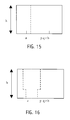
- FIG. 15 is a graph showing an exemplary vertical path within a tile.
- FIG. 16 is a graph showing an exemplary vertical path within a tile.
- FIG. 17 is a graph showing an exemplary short path between target and boundary segment.
- FIG. 18 is a graph showing an exemplary short path between boundary segments.
- FIG. 20 is a flow chart showing an exemplary forward leg sweep of FIG. 19 .
- FIG. 21 is a graph showing a exemplary piecewise cost function being clipped during the forward leg sweep of FIG. 20 .
- FIG. 22 is a graph showing a convex hull of a tile segment and a target tile in an exemplary routing area.
- FIG. 24 is a flow chart showing an exemplary method of cost propagation.
- FIG. 25 is a flow chart showing an exemplary method of path reconstruction.
- FIG. 26 is a block diagram of an exemplary system incorporating modules for use according to the present invention.
- FIG. 1 shows an example of a routing area 10 including obstacles 15 and 16 (sometimes designated “A” and “B,” respectively).
- the goal is to find a path from source 12 (sometimes designated “S”) through the clear space of routing area 10 around obstacles 15 and 16 to target 18 (sometimes designated “T”).
- the source and target are locations or end points between which a path is desired and are distinguished by an arbitrary decision to start searching for the target end point starting at the source end point.
- the source and target are treated as points.
- the source and tile may in fact be tiles (e.g., rectilinear tiles including boundary segments).
- each path consists of an alternating sequence of vertical and horizontal line segments joined at the ends.
- the weight ⁇ may be less than (or greater than) the weight ⁇ , for example, in order to encourage preferential routing in the horizontal (or vertical) direction. Also, ⁇ and ⁇ may vary from tile to tile (defined hereafter) to discourage routing in areas that are known to be congested (for example, because of an earlier global routing analysis).
- FIG. 5 shows exemplary routing area 10 wherein the routing region outside of obstacles A and B is fractured into seven clear tiles C 1 through C 7 .
- the tiles are rectangular.
- Tile C 5 includes source S
- tile C 3 includes target T.
- FIG. 3 shows a tile graph 30 constructed using clear tiles C 1 -C 7 .
- Each clear tile is a node in tile graph 30 . Whenever two clear tiles touch in FIG. 2, an edge in tile graph 30 connects their corresponding nodes. In tile graph 30 , an edge connects target T and tile C 3 , and an edge connects source S and tile C 5 .
- Tile graphs such as tile graph 30 are useful because they are compact. Both the number of clear tiles and the number of edges between clear tiles are linear in the number of solid tiles. This is a significant improvement over other graphing methods in which the computational features can be quadratic or geometric in the number of relevant graph features (e.g., nodes). Typically, for identical geometry, the tile graph representation is much smaller than superimposed grid techniques (uniform or non-uniform) and line probe techniques, all of which are well known in the art.
- a tile graph in accordance with the invention can be used to find the shortest path. Note that there may be multiple “shortest paths” as more than one path may have the same shortest length or cost.
- the embodiments described herein use an exact, piecewise linear, cost model to guide the search for the shortest path in the tile graph. This allows a much more compact graph search than past grid graphs while still finding the shortest path.
- Tile graph 30 is explored beginning with the tile containing the source (tile C 5 in FIG. 2 for example).
- the search centers on the boundaries between clear tiles. For example, it considers movement from source S to the boundary between tiles C 4 and C 5 , or from source S to the boundary between tiles C 5 and C 7 .
- boundary segments are referred to herein as boundary segments, and are noted using exemplary notation such as “boundary segment (C 5 , C 7 ).”
- Each boundary segment is assigned an associated source cost and back pointer, both of which are described in further detail below.
- FIG. 4 depicts the piecewise linear source cost for boundary segment (C 4 , C 5 ).
- X c5-min and X c5-max are the minimum and maximum coordinates, respectively, of boundary segment (C 4 , C 5 )
- x s is the x coordinate of the source point, S.
- each boundary segment is associated with at least one back pointer that facilitates the reconstruction of the shortest path.
- This back pointer always points to the preceding boundary segment (or to the source point, S) along the path from the source to the boundary segment in question.
- searching begins by initializing the costs (e.g., source and/or path costs) and back pointers of all boundary segments of the tile containing the source during initialize operation 525 .
- the cost e.g., the source cost
- the costs for the target e.g., the path cost
- all boundary segments are initialized to another value (e.g., a maximal value such as infinity).
- the source and target are rectilinear tiles, and the source tile boundary segments are assigned an initial path cost, which is the lower bound on the cost of some (yet to be discovered) path from the source to the target passing through this boundary segment.
- a path cost is computed for each boundary segment of the current tile during compute operation 530 .
- the path cost is computed by first forming the sum of two piecewise linear functions: the source cost and the target cost.
- the source cost is defined above.
- the target cost gives a lower bound on the cost of a path from each point on a boundary segment to the target.
- the value of the target cost function at each point on the boundary segment is given by the weighted Manhattan distance between that point and the target.
- the weighted Manhattan distance is computed using the weights: ⁇ min and ⁇ min , given by the minimum values of ⁇ and ⁇ over all clear tiles.
- the path cost is the minimum value of the sum of the source cost and the target cost taken at each point on the boundary segment. Calculation of an estimated target cost is discussed in greater detail below with reference at least to FIGS. 22 and 23.
- the priority queue is checked during decision 560 . If the priority queue is not empty, control transitions to decision 565 during which it is determined whether the target's source cost is less than the path cost of the next boundary segment in the priority queue. If the target's source cost is greater than the path cost of the next boundary segment in the priority queue, then control transitions to operation 540 and the search is continued until either the priority queue is empty at decision 560 or the target's source cost is less than the path cost of the next boundary segment in the priority queue at decision 565 .
- a boundary segment is popped from the queue.
- the well known A* search heuristic is used to decide which boundary segment to visit next.
- the segment with the smallest path cost is always at the top of the priority queue. This is the segment to be visited next.
- the priority queue initially holds segments (C 4 , C 5 ) and (C 5 , C 7 ) (see, e.g., FIGS. 3 and 7 ).
- Segment (C 4 , C 5 ) is the first segment to be removed from the queue because it has the smallest path cost and is at the front of the queue. When it is removed, the search moves from the source S to segment (C 4 , C 5 ).
- decision 550 directs a transition to compute new target source cost operation 555 if the target has been reached or to estimate path costs operation 545 if the target tile has not been reached.
- exit boundary segment source costs operation 545 the cost of paths from the source through the entry segment to the new tile's other boundary segments, the exit segments, are calculated.
- Each of exit segment may or may not be different from the entry segment.
- a new source cost is computed for each exit segment and compared to the source cost already stored on that segment (e.g., an initialized value of the source cost). If the newly computed source cost is less than the old source cost (at any point), then a shorter path has been found. In that case that exit segment's source cost is set to the minimum of the two source costs, the back pointer(s) is(are) updated, and the segment is entered into the priority queue at the appropriate location for future consideration.
- exit segment source cost is a piecewise linear function, and a scalar value (e.g., the minimum knot value) is determined for prioritization.
- the entry point e.g., x E which gives the minimum source cost to the exit segment is recorded for future use during back tracking to determine the shortest path (see, e.g., discussion referring to FIG. 25 ).
- the next boundary segment is removed from the priority queue and the search continues recursively at operation 540 .
- (C 4 , C 3 ) will be removed from the priority queue because it has the smallest path cost.
- the search process continues recursively, initially with tile C 3 , for example.
- a tile containing the target, T is encountered at target tile decision 550 , then a path has been found from the source to the target.
- the source cost of the entry segment is used to compute a new source cost for the target during compute new target source cost operation 555 . Since the target is a point, its source cost is a scalar value. If the new source cost is lower than the target's previous source cost, then a new shortest path has been found. Control then transitions to decision 560 . As discussed above, the search is continued at operation 540 unless either the priority queue is empty at decision 560 or the target's source cost is less than the path cost of the next boundary segment in the priority queue at decision 565 .
- the source cost of the target gives the weighted Manhattan distance of the shortest path from S to T.
- the back pointer stored at the target can be followed to retrace, in reverse order, the sequence of boundary segments visited by the shortest path, as illustrated in FIG. 8 and as discussed in greater detail below (e.g., with reference to FIG. 25, et al.). If neither condition is satisfied during decisions 560 and 565 , control returns to operation 540 where the next boundary segment is selected.
- the path cost for a boundary segment is equal to the minimum value of the sum of the source cost and the target cost taken at each point on the boundary segment.
- the value of the target cost function at each point on the next selected exit boundary segment is determined during operation 610 .
- a new source cost is computed for each exit segment and compared to the source cost already stored on that segment. If the newly computed source cost is less than the old source cost (at any point), that exit segment's source cost is set to the minimum of the two source costs during operation 630 .
- the path cost is calculated from the source and target costs. Having determined a path cost during operation 650 , the segment may be entered into the priority queue at the appropriate location for future consideration.
- the A* search method is attractive because it balances real cost and estimated cost.
- an estimated cost is calculated during operation 610 . If the target is a point, then the estimated cost is simply a manhattan distance to the target.
- a method of calculating the estimated cost of a segment to the destination tile T will now be discussed with reference to FIGS. 22 and 23.
- segment AB is the segment which is the subject of target cost estimation in the presently discussed example.
- the vertices of target tile T are CDEF. The cost from any point on AB and any point in T is evaluated using the smallest horizontal and vertical unit cost.
- FIG. 23 shows a method of estimating a target cost from a segment AB to a rectangular target tile T.
- find hull operation 2310 the convex hull of the segment AB and the target tile T is found.
- the convex hull containing AB and T is ABDEF.
- the minimum cost function to four sides of the target tile T can be evaluated.
- a brute force method involves the application of the cost propagation method provided herein four times, one for each side of the target tile T.
- the orientation of the segment to the selected target side is determined during decision 2330 . If the selected target side is determined to be parallel to AB during decision 2330 , then a method of cost propagation between parallel line segments is used to compute the minimum cost function to the target tile T during parallel cost calculation operation 2340 . Alternatively, if the selected target side is determined to be perpendicular to segment AB during decision 2330 , then a method of cost propagation between perpendicular line segments is used to compute the minimum cost function to the target tile T during perpendicular cost calculation operation 2350 . Exemplary parallel and perpendicular cost propagation is discussed below with reference to the Linear Minimal Convolution which is introduced herein.
- LMC Linear Minimal Convolution
- n end points of those segments as knots: (x i , f(x i )), where 1 ⁇ i ⁇ n, and x i ⁇ x 2 ⁇ . . . ⁇ x n .
- the entry and exit segments may be perpendicular or parallel to each other.
- a determination is made during decision 2410 as to whether the entry and exit segments are parallel or perpendicular. If the segments are perpendicular control transitions to a set of operations 2432 , 2434 , 2436 , 2438 which provide a method of perpendicular cost propagation, and if the segments are parallel control transitions to a set of operations 2424 , 2426 which provide a method of parallel cost propagation.
- the source cost to the exit segment may be determined by adding the source cost at the entry segment to the cost of the path from the entry segment to the exit segment (e.g., a propagation cost).
- the cost of the path from the entry segment to the exit segment is not explicitly calculated.
- are found during operation 2432 .
- the function p(x) f(x)+ ⁇
- is the sum of two piecewise linear functions and therefore is also piecewise linear. Since the minimum of a piecewise linear function must occur at one if its knots, m can be found by examining the knots of p(x) during operation 2434 , and taking the minimum of such knot points during operation 2436 .
- the source cost at the exit segment, g(y) is a piecewise linear function which may be found by analyzing it's knot point(s) (e.g., 1-3 points) during operation 2438 .
- the source cost to the exit segment is calculated by adding the source cost at the entry segment to the cost of the path from the entry segment to the exit segment. Let the vertical span or height of the clear tile be h.
- g ⁇ ( x ) min ⁇ ⁇ [ a , b ] ⁇ ⁇ f ⁇ ( ⁇ ) + ⁇ ⁇ ⁇ ⁇ - x ⁇ ⁇ + ⁇ ⁇ ⁇ h
- ⁇ h is a constant determined by the vertical weight factor ⁇ and the vertical span or height h of the tile in question during operation 2422 .
- the function min ⁇ ⁇ [ a , b ] ⁇ ⁇ f ⁇ ( ⁇ ) + ⁇ ⁇ ⁇ ⁇ - x ⁇ ⁇
- LMC linear minimum convolution
- the notation ( ⁇ *f)(x) is used to represent the linear minimal convolution (LMC) of a weight ⁇ (where ⁇ 0) with a function f(x) (sometimes designated herein as the piecewise linear function L).
- LMC linear minimal convolution
- ( ⁇ *f)(x) is a semi-infinite line with a slope of ⁇ .
- ( ⁇ *f)(x) is a semi-infinite line with a slope of ⁇ .
- the LMC kernel includes a forward leg 1130 which is the line with slope ⁇ , and a backward leg 1120 which is the line with slope ⁇ .
- Each value in the domain of f(x) has contributed one LMC Kernel.
- the LMC is the minimum of all the kernels.
- the dashed line represents the portions of the LMC Kernels that are clipped away when the minimum is taken. Those portions don't contribute to the LMC.
- the domain of f(x) consists of any number of values.
- the domain of f(x) is composed of an infinite number of values.
- Each of those values contributes an LMC Kernel.
- the LMC is given by the minimum of an infinite number of LMC kernels.
- FIG. 14 An example of a resulting linear minimum convolution of a piecewise linear function is FIG. 14 .
- f(x) (presumed to be piecewise linear) is plotted with a thick line.
- the LMC kernels, plotted with thin lines, are the wedges with vertices resting on f(x).
- the LMC plotted with a dashed line, is the minimum of all the LMC kernels.
- the LMC computation may be visualized as sliding the vertex of an LMC Kernel along f(x) while tracing the envelope of all the lowest points touched by the LMC Kernel.
- the first LMC yields a piecewise linear function with line segments with slope magnitudes less than ⁇ 1 (from the previous property).
- an LMC kernel with steeper slopes ⁇ 2 slides along a function with shallower slopes then no new minimums will be found.
- displacing a function displaces its LMC as well.
- the LMC of a linear function is a piecewise linear function.
- the LMC computation may be effectively used to choose paths through the tiles.
- the source cost at any point along a line a distance h away from the entry segment is the sum of two terms. (See FIG. 15 showing the choice of path in tile.)
- ⁇ h is the cost of the vertical portion of the path inside this tile.
- ( ⁇ *f)(x) (the LMC) is the source cost from the entry segment plus the cost of the horizontal portion of the path inside this tile.
- the LMC envelope is composed from two kinds of line segments: those that originate from the source cost function f(x) (the thick lines in FIG. 14 ), and those that originate from the shifted LMC Kernel (the thin lines). Segments originating from the source cost function represent intervals over which the shortest path in this tile is entirely vertical. A typical path for the interval a ⁇ x ⁇ p is shown in FIG. 15 which shows vertical paths. On the other hand, segments of the LMC originating from the (shifting) LMC Kernel represent intervals over which the shortest path makes a horizontal traversal.
- FIG. 16 shows two examples of this kind of path, one for the interval x ⁇ a, and one for the interval p ⁇ x ⁇ q. Each has horizontal jogs.
- implicit in the computation of the LMC is the selection of the path through the current tile. This suggests a method for reconstructing the path which is discussed in greater detail below.
- the LMC of a piecewise linear function can be found by finding the minimum of the LMCs of all the functions linear segments. For example, assume f(x) is piecewise linear defined as
- the brute force approach of finding the LMC of f(x) is to compute ( ⁇ *f i )(x) first.
- Function ( ⁇ *f)(x) can be computed by finding the minimum of all functions ( ⁇ *f i )(x).
- the fastest algorithm for finding the minimum function of two piecewise linear functions is linear in terms of n, the number of segments. Therefore, the brute force algorithm to computer LMC of f(x) is quadratic in terms of number of segments.
- Another method may be more preferred since it is a linear algorithm to compute the LMC of f(x). For every linear segment f i (x), ( ⁇ *f)(x) has two infinite lines, a backward leg and a forward leg. The LMC of f(x) can be found by clipping f(x) using all the legs and saving the lower line segments. This algorithm has two sweeps: a forward clipping sweep and a backward clipping sweep.
- the forward leg l intersects f(x) at C.
- the slope of f i (x) must be less than ⁇ .
- the right end point (a i+1 , f(a i+1 )) must be below line l.
- the forward leg l′ starting from (a i+1 ,f(a i+1 )) must be below l, i.e., in the interval [a i+1 , ⁇ ) l′ is lower than l. Therefore, l is no longer clipping.
- f i (x) itself is lower than l. Therefore, in the remaining interval [c, ⁇ ), l is not clipping.
- the backward leg case can be proved the same way as the forward leg case.
- FIG. 19 shows a linear running time method of finding the LMC of the piecewise linear function f(x).
- a positive number ⁇ and a list L are received during input operation 1910 .
- the list L ⁇ l 0 , l 1 , . . . , l n-1 ⁇ is a sorted list of line segments that represents the continuous piecewise linear function f(x) for an entry boundary segment
- forward leg sweep operation 1920 a forward clipping sweep is performed on the input cost function. The forward clipping sweep is discussed in greater detail below with reference to FIG. 20 .
- a backward clipping sweep is performed.
- the backward clipping sweep is analogous to the forward clipping sweep except in the opposite direction, and is easily implemented by one of ordinary skill in the art based on the teaching herein regarding the forward clipping sweep.
- the LMC of the cost function is output as a result from sweep operations 1920 and 1930 .
- L the list of line segments that represents ( ⁇ * f)(x), a continuous piecewise linear function is provided.
- the source cost of the exit segment may be calculated using the LMC of the entry cost function as discussed herein.
- FIG. 20 shows a method of implementing a forward clipping sweep. Assuming the boundary segments are sorted (as in operation 535 of FIG. 5 ), the next boundary segment is selected during operation 2010 of FIG. 20. A list of knot points corresponding to the selected segment is also selected. A first point a i (e.g., a first endpoint a) of the boundary segment is selected to begin the forward sweep during operation 2020 .
- any forward leg originating from point a i (e.g., a knot of the cost function) of the boundary segment is clipping.
- a line segment is clipping if it intersects any piecewise linear segment of the cost function. More specifically, at any given point a i not including the other endpoint b of the selected boundary segment, a forward leg starting from (a i ,f(a i )) is clipping if the slope of f i (x) is greater than ⁇ . When the slope of f i (x) is positive and greater than ⁇ , the leg goes under the segment and therefore it is clipping.
- the LMC of f(x) includes only parts of line segments of f(x), forward legs and backward legs.
- the clipping process chops out the parts of segments that are not part of the LMC. After a clipping forward leg intersects f(x), the remaining line segment is no longer clipping.
- the backward sweep is substantially the opposite of the forward sweep, starting from endpoint b and clipping the modified piecewise linear function using all clipping backward legs.
- a backward leg starting from (a i ,f(a i )) is clipping if and only if the slope of f i-1 (x) is negative and less than ⁇ . After a clipping backward leg intersects f(x), the remaining line segment is no longer clipping.
- the search algorithm terminates, the sequence of boundary segments visited by the shortest path are known.
- the shortest path may then be reconstructed from the piecewise linear source costs stored in those boundary segments.
- One method is to record the origin of each segment of the piecewise linear function computed by the LMC (e.g., whether it is from f(x) or the LMC kernel).
- a router typically spends the bulk of its time in the search phase and this approach may slow down the search. It is more efficient to simply rerun the LMC calculation over the much smaller number of boundary segments in the back trace.
- Path reconstruction begins with the portion of the shortest path lying within the tile containing the target (e.g., the path from the target to a point on the boundary segment found to be part of the shortest path).
- the back pointer in the target e.g., represented by the arrow in FIG. 17
- that entry boundary segment of the target tile is found during find target entry segment operation 2510 .
- find minimum point operation 2515 the point P(x p ,y p ) on the entry segment with the minimum source cost is found.
- control transitions to insert minimum point operation 2520 .
- the point P(x p ,y p ) is inserted into a list of points on the path from the source to the target.
- the entry segment (s) in the previous tile T is found during find previous entry segment operation 2525 .
- the first operation of horizontal operations 2550 is find source cost function operation 2552 .
- find source cost operation 2552 the source cost function f(x) on the segment s is found.
- Path reconstruction uses the equations for source cost propagation described above to find the x-value of the point P through which the shortest path intersects the segment s. However, during path reconstruction the target's position and source cost is known, and we wish to recover the point on the entry segment that gave us this minimum cost. Let the coordinates of the target be: (x T , y T ).
- the x value of the knot point which gives the minimum value m is recorded during operation 2556 , for example.
- the shortest path enters this tile through the point on the entry segment: (x m ,y BL ).
- An analogous method may be used for calculating a horizontal segment at the top of a tile.
- the point P may be recorded because the y value is already known. For example, when the segment is horizontal as shown in FIG. 17, the vertical or y location of the entry point is known (e.g., y BL ) since the value for y is the same for the entirety of the entry segment. Thus, the point P is determined to be (x m , s y ) during set path point operation 2558 .
- Path reconstruction uses the equations for source cost propagation described above to find y during operations 2560 .
- the knot points of the source cost function are found.
- the list of knot points of the piecewise linear function g 1 (y) g(y)+ ⁇
- is found during find knot points operation 2564 .
- the knot point that provides the minimum value of the function g 1 (y) is found during operation 2564 .
- the point P through which the path intersects the entry segment s is set to (s x ,y m ) during set path point operation 2568 .
- a new entry segment is selected using backpointer(s) in subsequent operations thereafter.
- the shortest path through this tile is represented by the dashed line. Note that the shortest path may not be unique. For example, a stair case would have the same weighted Manhattan distance.
- the above calculation is repeated recursively back to the source to construct the remainder of the path.
- the entry point for this tile becomes the exit point for the preceding tile and we repeat the calculation for the preceding boundary segment as shown in FIG. 25 .
- Given a fixed exit point we calculate the coordinates of the entry point.
- the recursive execution terminates after decision 2530 .
- the complete shortest path is formed by concatenating the pieces found during the back trace.
- the foregoing description sets forth a novel shortest path search algorithm based on the propagation of piecewise linear costs between the boundaries of clear tiles in a tile graph. Unlike earlier tile algorithms, the above described algorithm always finds the shortest path. Unlike the earlier non-uniform grid graph algorithms, the above described algorithm traverses the tile graph which is much smaller than a grid graph.
- One factor related to the efficiency of the above described algorithm is the observation that for VLSI routing examples, the number of knots in the piecewise linear costs is constant. This implies that one can traverse an edge in the tile graph in constant time.
- the operations discussed herein may consist of steps carried out by system users, hardware modules and/or software modules.
- the operations of FIGS. 5, 6 , 19 , 20 and 23 are directly or indirectly representative of software modules resident on a computer readable medium and/or resident within a computer system and/or transmitted to the computer system as part of a computer program product.
- the operations referred to herein may correspond to modules or portions of modules (e.g., software, firmware or hardware modules, or combinations thereof).
- the functionality of operations referred to herein may correspond to the functionality of modules or portions of modules in various embodiments.
- modules are merely illustrative and alternative embodiments may merge modules or impose an alternative decomposition of functionality of modules.
- the modules discussed herein may be decomposed into submodules to be executed as multiple computer processes.
- alternative embodiments may combine multiple instances of a particular module or submodule.
- Computer systems may be found in many forms including but not limited to mainframes, minicomputers, servers, workstations, personal computers, notepads, personal digital assistants, various wireless devices and embedded systems, just to name a few.
- a typical computer system includes at least one processing unit, associated memory and a number of input/output (I/O) devices.
- I/O input/output
- a computer system processes information according to a program and produces resultant output information via I/O devices.
- a program is a list of instructions such as a particular application program and/or an operating system.
- a computer program is typically stored internally on computer readable storage media or transmitted to the computer system via a computer readable transmission medium.
- a computer process typically includes an executing (running) program or portion of a program, current program values and state information, and the resources used by the operating system to manage the execution of the process.
- a parent computer process may spawn other, child processes to help perform the overall functionality of the parent process. Because the parent process specifically spawns the child processes to perform a portion of the overall functionality of the parent process, the functions performed by child processes (and grandchild processes, etc.) may sometimes be described as being performed by the parent process.
- FIG. 26 shows an exemplary embodiment in which the software modules described above are stored within a computer system 2600 on computer readable media 2620 .
- the software modules may be stored on media 2620 as routing module(s) 2630 .
- Routing module(s) 2630 are coupled to processing unit(s) 2610 to configure system 2600 to operate on routing data 2640 .
- Routing data 2640 may include information pertaining to a design area, design assumptions, objects and space therein; routes and graphs related thereto, cost functions thereof, etc.
- Computer readable media 2620 may be permanently, removably or remotely coupled to system 2600 and/or processing unit(s) 2610 .
- Computer readable media 2620 may include, for example and without limitation, any number of the following: magnetic storage media including disk and tape storage media; optical storage media such as compact disk media (e.g., CD-ROM, CD-R, etc.) and digital video disk storage media; holographic memory; nonvolatile memory storage media including semiconductor-based memory units such as FLASH memory, EEPROM, EPROM, ROM; ferromagnetic digital memories; volatile storage media including registers, buffers or caches, main memory, RAM, etc.; and data transmission media including permanent and intermittent computer networks, point-to-point telecommunication equipment, and carrier wave transmission media, just to name a few. Other new and various types of computer-readable media may be used to store and/or transmit the software modules discussed herein.
- magnetic storage media including disk and tape storage media
- optical storage media such as compact disk media (e.g., CD-ROM, CD-R, etc.) and digital video disk storage media
- holographic memory nonvolatile memory storage media including semiconductor-based memory units such as FLASH memory
- any two components herein combined to achieve a particular functionality can be seen as “associated with” each other such that the desired functionality is achieved, irrespective of architectures or intermedial components.
- any two components so associated can also be viewed as being “operably connected”, or “operably coupled”, to each other to achieve the desired functionality.
- the claim reads on the apparatus or method regardless of whether the apparatus or method includes another such similar feature.
- This use of the word “a” as a nonlimiting, introductory article to a feature of a claim is adopted herein by Applicants as being identical to the interpretation adopted by many courts in the past, notwithstanding any anomalous or precedential case law to the contrary that may be found.
- a claim element is described in the claims below as including or comprising an aforementioned feature (e.g., “the” feature), it is intended that the element not be limited to one and only one of the feature described merely by the incidental use of the definite article.
Priority Applications (1)
| Application Number | Priority Date | Filing Date | Title |
|---|---|---|---|
| US09/998,558 US6665852B2 (en) | 2000-12-01 | 2001-11-30 | Piecewise linear cost propagation for path searching |
Applications Claiming Priority (3)
| Application Number | Priority Date | Filing Date | Title |
|---|---|---|---|
| US25062700P | 2000-12-01 | 2000-12-01 | |
| US30967201P | 2001-08-02 | 2001-08-02 | |
| US09/998,558 US6665852B2 (en) | 2000-12-01 | 2001-11-30 | Piecewise linear cost propagation for path searching |
Publications (2)
| Publication Number | Publication Date |
|---|---|
| US20020100009A1 US20020100009A1 (en) | 2002-07-25 |
| US6665852B2 true US6665852B2 (en) | 2003-12-16 |
Family
ID=27400344
Family Applications (1)
| Application Number | Title | Priority Date | Filing Date |
|---|---|---|---|
| US09/998,558 Expired - Lifetime US6665852B2 (en) | 2000-12-01 | 2001-11-30 | Piecewise linear cost propagation for path searching |
Country Status (1)
| Country | Link |
|---|---|
| US (1) | US6665852B2 (US06665852-20031216-M00008.png) |
Cited By (26)
| Publication number | Priority date | Publication date | Assignee | Title |
|---|---|---|---|---|
| US20020104061A1 (en) * | 2000-12-01 | 2002-08-01 | Sun Microsystems, Inc. | Systems and methods for linear minimal convolution |
| US20020107711A1 (en) * | 2000-12-01 | 2002-08-08 | Sun Microsystems, Inc. | Short path search using tiles and piecewise linear cost propagation |
| US20030009737A1 (en) * | 2001-04-06 | 2003-01-09 | Zhaoyun Xing | Detailed method for routing connections using tile expansion techniques and associated methods for designing and manufacturing VLSI circuits |
| US20030038850A1 (en) * | 2001-08-24 | 2003-02-27 | Formfactor, Inc. | Process and apparatus for adjusting traces |
| US20030046646A1 (en) * | 2001-09-03 | 2003-03-06 | Fujitsu Limited | Integrated circuit design apparatus, method and program |
| US20030106036A1 (en) * | 2001-12-03 | 2003-06-05 | Katsushi Aoki | Wiring route determining apparatus, group determining apparatus, wiring route determining program storing medium and group determining program storing medium |
| US20040088670A1 (en) * | 2001-08-24 | 2004-05-06 | Formfactor, Inc. | Process and apparatus for finding paths through a routing space |
| US20040088722A1 (en) * | 2002-11-01 | 2004-05-06 | Peker Kadir A. | Pattern discovery in multi-dimensional time series using multi-resolution matching |
| US20040098691A1 (en) * | 2002-11-18 | 2004-05-20 | Steven Teig | Method and apparatus for performing an exponential path search |
| US20040236811A1 (en) * | 2003-05-19 | 2004-11-25 | Kode, A Corporation Of France | Method of computation of a short path in valued graphs |
| US6886149B1 (en) | 2002-01-22 | 2005-04-26 | Cadence Design Systems, Inc. | Method and apparatus for routing sets of nets |
| US6889372B1 (en) | 2000-07-15 | 2005-05-03 | Cadence Design Systems Inc. | Method and apparatus for routing |
| US6889371B1 (en) | 2002-06-04 | 2005-05-03 | Cadence Design Systems, Inc. | Method and apparatus for propagating a function |
| US6892371B1 (en) | 2002-01-22 | 2005-05-10 | Cadence Design Systems, Inc. | Method and apparatus for performing geometric routing |
| US6915499B1 (en) | 2002-06-04 | 2005-07-05 | Cadence Design Systems, Inc. | Method and apparatus for propagating a piecewise linear function to a line |
| US6951005B1 (en) | 2001-06-03 | 2005-09-27 | Cadence Design Systems, Inc. | Method and apparatus for selecting a route for a net based on the impact on other nets |
| US7047512B1 (en) * | 2002-06-04 | 2006-05-16 | Cadence Design Systems, Inc. | Method and apparatus for specifying a cost function that represents the estimated distance between an external state and a set of states in a space |
| US20060129314A1 (en) * | 2004-12-09 | 2006-06-15 | Lg Electronics Inc. | Navigation system |
| US7069531B1 (en) * | 2002-07-15 | 2006-06-27 | Cadence Design Systems, Inc. | Method and apparatus for identifying a path between source and target states in a space with more than two dimensions |
| US7107564B1 (en) | 2001-06-03 | 2006-09-12 | Cadence Design Systems, Inc. | Method and apparatus for routing a set of nets |
| US20070104029A1 (en) * | 2005-11-09 | 2007-05-10 | Lsi Logic Corporation | Method and computer program for spreading trace segments in an integrated circuit package design |
| US20070129885A1 (en) * | 2005-11-09 | 2007-06-07 | Harald Wellmann | Optimum route determination with tiling |
| US7375731B2 (en) * | 2002-11-01 | 2008-05-20 | Mitsubishi Electric Research Laboratories, Inc. | Video mining using unsupervised clustering of video content |
| US20080256502A1 (en) * | 2007-04-11 | 2008-10-16 | International Business Machines Corporation | System and method for global circuit routing incorporating estimation of critical area estimate metrics |
| US20090111255A1 (en) * | 2007-10-29 | 2009-04-30 | Hynix Semiconductor Inc. | Method for fabricating transistor in semiconductor device |
| US20120144358A1 (en) * | 2010-12-02 | 2012-06-07 | International Business Machines Corporation | Resolving Global Coupling Timing and Slew Violations for Buffer-Dominated Designs |
Families Citing this family (16)
| Publication number | Priority date | Publication date | Assignee | Title |
|---|---|---|---|---|
| US6900228B1 (en) * | 1998-03-10 | 2005-05-31 | Research Triangle Institute | Opiate compounds, methods of making and methods of use |
| US6898773B1 (en) | 2002-01-22 | 2005-05-24 | Cadence Design Systems, Inc. | Method and apparatus for producing multi-layer topological routes |
| US7441220B2 (en) * | 2000-12-07 | 2008-10-21 | Cadence Design Systems, Inc. | Local preferred direction architecture, tools, and apparatus |
| US6829757B1 (en) | 2001-06-03 | 2004-12-07 | Cadence Design Systems, Inc. | Method and apparatus for generating multi-layer routes |
| US6944841B1 (en) | 2002-01-22 | 2005-09-13 | Cadence Design Systems, Inc. | Method and apparatus for proportionate costing of vias |
| US7117468B1 (en) | 2002-01-22 | 2006-10-03 | Cadence Design Systems, Inc. | Layouts with routes with different spacings in different directions on the same layer, and method and apparatus for generating such layouts |
| US7096449B1 (en) | 2002-01-22 | 2006-08-22 | Cadence Design Systems, Inc. | Layouts with routes with different widths in different directions on the same layer, and method and apparatus for generating such layouts |
| US6973634B1 (en) | 2002-01-22 | 2005-12-06 | Cadence Design Systems, Inc. | IC layouts with at least one layer that has more than one preferred interconnect direction, and method and apparatus for generating such a layout |
| US6892369B2 (en) * | 2002-11-18 | 2005-05-10 | Cadence Design Systems, Inc. | Method and apparatus for costing routes of nets |
| CA2553627A1 (en) * | 2004-01-15 | 2005-07-28 | Algotec Systems Ltd. | Vessel centerline determination |
| US7580812B2 (en) * | 2004-01-28 | 2009-08-25 | Honeywell International Inc. | Trending system and method using window filtering |
| US7707537B2 (en) * | 2004-06-04 | 2010-04-27 | Cadence Design Systems, Inc. | Method and apparatus for generating layout regions with local preferred directions |
| EP1867952B1 (en) * | 2006-06-13 | 2009-12-09 | Harman/Becker Automotive Systems GmbH | Optimum route determination employing an estimation function |
| US8250514B1 (en) * | 2006-07-13 | 2012-08-21 | Cadence Design Systems, Inc. | Localized routing direction |
| CN110390607B (zh) * | 2019-07-22 | 2022-02-22 | 广联达科技股份有限公司 | 基于科目指标体系的目标成本测算方法、系统和计算机可读存储介质 |
| CN111915488B (zh) * | 2020-08-05 | 2023-11-28 | 成都圭目机器人有限公司 | 大数据下的高性能图像瓦块图生成方法 |
Citations (1)
| Publication number | Priority date | Publication date | Assignee | Title |
|---|---|---|---|---|
| US6324675B1 (en) * | 1998-12-18 | 2001-11-27 | Synopsys, Inc. | Efficient iterative, gridless, cost-based fine router for computer controlled integrated circuit design |
-
2001
- 2001-11-30 US US09/998,558 patent/US6665852B2/en not_active Expired - Lifetime
Patent Citations (1)
| Publication number | Priority date | Publication date | Assignee | Title |
|---|---|---|---|---|
| US6324675B1 (en) * | 1998-12-18 | 2001-11-27 | Synopsys, Inc. | Efficient iterative, gridless, cost-based fine router for computer controlled integrated circuit design |
Non-Patent Citations (8)
| Title |
|---|
| Arnold, M. H. and Scott, W. S., "An Interactive Maze Router with Hints," 25th ACM/IEEE Design Automation Conference, 1988, Paper 41.4, pp. 672-676. |
| Cong, Jason et al, "An Implicit Connection Graph Maze Routing Algorithm for ECO Routing," ACM SIGDA proceedings 1999, Session 3B: Routing, 5 pp.; [online] Downloaded from the Internet May 14, 2002, URL: <http://www.sigda.org/Archives/ProceedingsArchives/Iccad99/pdffiles/03b 2.pdf>. |
| Dion, J. and Monier, L.M., "Contour: A Tile-based Gridless Router," WRL Research Report 95/3, Digital Western Research Laboratory, Palo Alto, CA, Mar. 1995, 30 pp. [online] Downloaded from the Internet May 14, 2002, URL: <ftp://gatekeeper.research.compaq.com/pub/DEC/WRL/research-reports/WRL-TR-95.3.pdf>. |
| Liu, Le-Chin E. et al., "Chip-Level Area Routing," International Symposium on Physical Design, Proceedings of the 1998 International Symposium on Physical, Monterey, CA, 1998, ACM Press, NY, NY pp. 197-204. |
| Margarino, A. et al., "A Tile-Expansion Router," IEEE Transactions on Computer-Aided Design, vol. CAD-6, No. 4, Jul. 1987, pp. 507-517. |
| Tsai, Chia-Chun et al., "An H-V Alternating Router," IEEE Transactions on Computer-Aided Design, vol. 11, No. 8, Aug. 1992, pp. 976-991. |
| Wu, Ying-Fung et al., "Rectilinear Shortest Paths and Minimum Spanning Trees in the Presence of Rectilinear Obstacles," IEEE Transactions on computers, vol. C-36, No. 3, Mar. 1987, pp. 321-331. |
| Zheng, S. Q. et al., "Finding Obstacle-Avoiding Shortest Paths Using Implicit Connection Graphs," IEEE Transactions on Computer-Aided Design of Integrated Circuits and Systems, vol. 15, No. 1, Jan. 1996, pp. 103-110. |
Cited By (54)
| Publication number | Priority date | Publication date | Assignee | Title |
|---|---|---|---|---|
| US6889372B1 (en) | 2000-07-15 | 2005-05-03 | Cadence Design Systems Inc. | Method and apparatus for routing |
| US7139992B2 (en) * | 2000-12-01 | 2006-11-21 | Sun Microsystems, Inc. | Short path search using tiles and piecewise linear cost propagation |
| US20020107711A1 (en) * | 2000-12-01 | 2002-08-08 | Sun Microsystems, Inc. | Short path search using tiles and piecewise linear cost propagation |
| US20020104061A1 (en) * | 2000-12-01 | 2002-08-01 | Sun Microsystems, Inc. | Systems and methods for linear minimal convolution |
| US20030009737A1 (en) * | 2001-04-06 | 2003-01-09 | Zhaoyun Xing | Detailed method for routing connections using tile expansion techniques and associated methods for designing and manufacturing VLSI circuits |
| US6763512B2 (en) * | 2001-04-06 | 2004-07-13 | Sun Microsystems, Inc. | Detailed method for routing connections using tile expansion techniques and associated methods for designing and manufacturing VLSI circuits |
| US7107564B1 (en) | 2001-06-03 | 2006-09-12 | Cadence Design Systems, Inc. | Method and apparatus for routing a set of nets |
| US6951005B1 (en) | 2001-06-03 | 2005-09-27 | Cadence Design Systems, Inc. | Method and apparatus for selecting a route for a net based on the impact on other nets |
| US7814453B2 (en) * | 2001-08-24 | 2010-10-12 | Formfactor, Inc. | Process and apparatus for finding paths through a routing space |
| US8015536B2 (en) | 2001-08-24 | 2011-09-06 | Formfactor, Inc. | Process and apparatus for adjusting traces |
| US7444623B2 (en) | 2001-08-24 | 2008-10-28 | Formfactor, Inc. | Process and apparatus for adjusting traces |
| US6862727B2 (en) * | 2001-08-24 | 2005-03-01 | Formfactor, Inc. | Process and apparatus for adjusting traces |
| US20040088670A1 (en) * | 2001-08-24 | 2004-05-06 | Formfactor, Inc. | Process and apparatus for finding paths through a routing space |
| US20030038850A1 (en) * | 2001-08-24 | 2003-02-27 | Formfactor, Inc. | Process and apparatus for adjusting traces |
| US20050148243A1 (en) * | 2001-08-24 | 2005-07-07 | Formfactor, Inc. | Process and apparatus for adjusting traces |
| US20030046646A1 (en) * | 2001-09-03 | 2003-03-06 | Fujitsu Limited | Integrated circuit design apparatus, method and program |
| US7191421B2 (en) * | 2001-09-03 | 2007-03-13 | Fujitsu Limited | Integrated circuit design apparatus, method and program evaluating condition of functional blocks, assigned to virtual placement regions in each of lower-and higher-rank mounting blocks |
| US20030106036A1 (en) * | 2001-12-03 | 2003-06-05 | Katsushi Aoki | Wiring route determining apparatus, group determining apparatus, wiring route determining program storing medium and group determining program storing medium |
| US6907594B2 (en) * | 2001-12-03 | 2005-06-14 | Fujitsu Limited | Wiring route determining apparatus, group determining apparatus, wiring route determining program storing medium and group determining program storing medium |
| US6892371B1 (en) | 2002-01-22 | 2005-05-10 | Cadence Design Systems, Inc. | Method and apparatus for performing geometric routing |
| US6886149B1 (en) | 2002-01-22 | 2005-04-26 | Cadence Design Systems, Inc. | Method and apparatus for routing sets of nets |
| US7013448B1 (en) | 2002-06-04 | 2006-03-14 | Cadence Design Systems, Inc. | Method and apparatus for propagating cost functions |
| US6889371B1 (en) | 2002-06-04 | 2005-05-03 | Cadence Design Systems, Inc. | Method and apparatus for propagating a function |
| US6978432B1 (en) | 2002-06-04 | 2005-12-20 | Cadence Design Systems, Inc. | Method and apparatus for propagating a piecewise linear function to a point |
| US6986117B1 (en) | 2002-06-04 | 2006-01-10 | Cadence Design Systems, Inc. | Method and apparatus for identifying a path between source and target states |
| US7246338B1 (en) | 2002-06-04 | 2007-07-17 | Cadence Design Systems, Inc. | Method and apparatus for computing cost of a path expansion to a surface |
| US7000209B1 (en) * | 2002-06-04 | 2006-02-14 | Cadence Design Systems, Inc. | Method and apparatus for propagating a piecewise linear function to a surface |
| US6931615B1 (en) * | 2002-06-04 | 2005-08-16 | Cadence Design Systems, Inc. | Method and apparatus for identifying a path between source and target states |
| US7047512B1 (en) * | 2002-06-04 | 2006-05-16 | Cadence Design Systems, Inc. | Method and apparatus for specifying a cost function that represents the estimated distance between an external state and a set of states in a space |
| US7051298B1 (en) | 2002-06-04 | 2006-05-23 | Cadence Design Systems, Inc. | Method and apparatus for specifying a distance between an external state and a set of states in space |
| US7058917B1 (en) | 2002-06-04 | 2006-06-06 | Cadence Design Systems, Inc. | Method and apparatus for specifying a cost function that represents the estimated distance between an external state and a set of states in a space |
| US6948144B1 (en) * | 2002-06-04 | 2005-09-20 | Cadence Design Systems, Inc. | Method and apparatus for costing a path expansion |
| US6915499B1 (en) | 2002-06-04 | 2005-07-05 | Cadence Design Systems, Inc. | Method and apparatus for propagating a piecewise linear function to a line |
| US7073151B1 (en) | 2002-06-04 | 2006-07-04 | Cadence Design Systems, Inc. | Method and apparatus for identifying a path between a set of source states and a set of target states in a triangulated space |
| US6931608B1 (en) * | 2002-06-04 | 2005-08-16 | Cadence Design Systems, Inc. | Method and apparatus for determining viability of path expansions |
| US7069531B1 (en) * | 2002-07-15 | 2006-06-27 | Cadence Design Systems, Inc. | Method and apparatus for identifying a path between source and target states in a space with more than two dimensions |
| US7103222B2 (en) * | 2002-11-01 | 2006-09-05 | Mitsubishi Electric Research Laboratories, Inc. | Pattern discovery in multi-dimensional time series using multi-resolution matching |
| US20040088722A1 (en) * | 2002-11-01 | 2004-05-06 | Peker Kadir A. | Pattern discovery in multi-dimensional time series using multi-resolution matching |
| US7375731B2 (en) * | 2002-11-01 | 2008-05-20 | Mitsubishi Electric Research Laboratories, Inc. | Video mining using unsupervised clustering of video content |
| US6996789B2 (en) * | 2002-11-18 | 2006-02-07 | Cadence Design Systems, Inc. | Method and apparatus for performing an exponential path search |
| US20040098691A1 (en) * | 2002-11-18 | 2004-05-20 | Steven Teig | Method and apparatus for performing an exponential path search |
| US20040236811A1 (en) * | 2003-05-19 | 2004-11-25 | Kode, A Corporation Of France | Method of computation of a short path in valued graphs |
| US7406047B2 (en) * | 2003-05-19 | 2008-07-29 | Kode | Method of computation of a short path in valued graphs |
| US20060129314A1 (en) * | 2004-12-09 | 2006-06-15 | Lg Electronics Inc. | Navigation system |
| US20070104029A1 (en) * | 2005-11-09 | 2007-05-10 | Lsi Logic Corporation | Method and computer program for spreading trace segments in an integrated circuit package design |
| US7325216B2 (en) * | 2005-11-09 | 2008-01-29 | Lsi Logic Corporation | Method and computer program for spreading trace segments in an integrated circuit package design |
| US7957894B2 (en) | 2005-11-09 | 2011-06-07 | Harman Becker Automotive Systems Gmbh | Optimum route determination with tiling |
| US20070129885A1 (en) * | 2005-11-09 | 2007-06-07 | Harald Wellmann | Optimum route determination with tiling |
| US9279692B2 (en) | 2005-11-09 | 2016-03-08 | Harman Becker Automotive Services Gmbh | Optimum route determination with tiling |
| US20080256502A1 (en) * | 2007-04-11 | 2008-10-16 | International Business Machines Corporation | System and method for global circuit routing incorporating estimation of critical area estimate metrics |
| US7685553B2 (en) * | 2007-04-11 | 2010-03-23 | International Business Machines Corporation | System and method for global circuit routing incorporating estimation of critical area estimate metrics |
| US20090111255A1 (en) * | 2007-10-29 | 2009-04-30 | Hynix Semiconductor Inc. | Method for fabricating transistor in semiconductor device |
| US20120144358A1 (en) * | 2010-12-02 | 2012-06-07 | International Business Machines Corporation | Resolving Global Coupling Timing and Slew Violations for Buffer-Dominated Designs |
| US8365120B2 (en) * | 2010-12-02 | 2013-01-29 | International Business Machines Corporation | Resolving global coupling timing and slew violations for buffer-dominated designs |
Also Published As
| Publication number | Publication date |
|---|---|
| US20020100009A1 (en) | 2002-07-25 |
Similar Documents
| Publication | Publication Date | Title |
|---|---|---|
| US6665852B2 (en) | Piecewise linear cost propagation for path searching | |
| US7139992B2 (en) | Short path search using tiles and piecewise linear cost propagation | |
| US20020104061A1 (en) | Systems and methods for linear minimal convolution | |
| Knowles et al. | Reducing local optima in single-objective problems by multi-objectivization | |
| Kahng et al. | Optimization of linear placements for wirelength minimization with free sites | |
| Ortega-Arranz et al. | The shortest-path problem: Analysis and comparison of methods | |
| Xing et al. | Shortest path search using tiles and piecewise linear cost propagation | |
| US8095904B2 (en) | Methods and apparatus for providing flexible timing-driven routing trees | |
| US20040216072A1 (en) | Porosity aware buffered steiner tree construction | |
| JP2013019910A (ja) | 近道発見装置 | |
| Sun et al. | On finding approximate optimal paths in weighted regions | |
| Dolinskaya et al. | Adaptive orienteering problem with stochastic travel times | |
| Zhou et al. | A Monte Carlo tree search framework for quantum circuit transformation | |
| Rakshit et al. | Efficient code for second order analysis of events on a linear network | |
| Lelis et al. | Predicting the size of depth-first branch and bound search trees. | |
| US6898774B2 (en) | Buffer insertion with adaptive blockage avoidance | |
| US20040202379A1 (en) | Method and system for finding spatial medians in a sliding window environment | |
| Sarmiento et al. | An efficient strategy for rapidly finding an object in a polygonal world | |
| JP4376670B2 (ja) | スタイナー木処理装置、スタイナー木処理方法及びスタイナー木処理プログラム | |
| Gerevini et al. | Incremental algorithms for managing temporal constraints | |
| Ono et al. | Constant time generation of linear extensions | |
| US20220083723A1 (en) | Electrical circuit design | |
| Hui | Network reliability estimation | |
| CN114490835A (zh) | 一种高效用项集挖掘方法、装置、电子设备和介质 | |
| US6314547B1 (en) | Method for improving the assignment of circuit locations during fabrication |
Legal Events
| Date | Code | Title | Description |
|---|---|---|---|
| AS | Assignment |
Owner name: SUN MICROSYSTEMS, INC., CALIFORNIA Free format text: ASSIGNMENT OF ASSIGNORS INTEREST;ASSIGNORS:XING, ZHAOYUN;KAO, RUSSELL;REEL/FRAME:012339/0827 Effective date: 20011129 |
|
| STCF | Information on status: patent grant |
Free format text: PATENTED CASE |
|
| CC | Certificate of correction | ||
| FPAY | Fee payment |
Year of fee payment: 4 |
|
| FPAY | Fee payment |
Year of fee payment: 8 |
|
| FPAY | Fee payment |
Year of fee payment: 12 |
|
| AS | Assignment |
Owner name: ORACLE AMERICA, INC., CALIFORNIA Free format text: MERGER AND CHANGE OF NAME;ASSIGNORS:ORACLE USA, INC.;SUN MICROSYSTEMS, INC.;ORACLE AMERICA, INC.;REEL/FRAME:037278/0746 Effective date: 20100212 |