US6663530B2 - Zero twist carrier - Google Patents
Zero twist carrier Download PDFInfo
- Publication number
- US6663530B2 US6663530B2 US10/017,152 US1715201A US6663530B2 US 6663530 B2 US6663530 B2 US 6663530B2 US 1715201 A US1715201 A US 1715201A US 6663530 B2 US6663530 B2 US 6663530B2
- Authority
- US
- United States
- Prior art keywords
- torque transfer
- planetary carrier
- transfer device
- torque
- coupling adapter
- Prior art date
- Legal status (The legal status is an assumption and is not a legal conclusion. Google has not performed a legal analysis and makes no representation as to the accuracy of the status listed.)
- Expired - Lifetime, expires
Links
Images


Classifications
-
- F—MECHANICAL ENGINEERING; LIGHTING; HEATING; WEAPONS; BLASTING
- F16—ENGINEERING ELEMENTS AND UNITS; GENERAL MEASURES FOR PRODUCING AND MAINTAINING EFFECTIVE FUNCTIONING OF MACHINES OR INSTALLATIONS; THERMAL INSULATION IN GENERAL
- F16H—GEARING
- F16H1/00—Toothed gearings for conveying rotary motion
- F16H1/28—Toothed gearings for conveying rotary motion with gears having orbital motion
- F16H1/46—Systems consisting of a plurality of gear trains each with orbital gears, i.e. systems having three or more central gears
-
- F—MECHANICAL ENGINEERING; LIGHTING; HEATING; WEAPONS; BLASTING
- F02—COMBUSTION ENGINES; HOT-GAS OR COMBUSTION-PRODUCT ENGINE PLANTS
- F02C—GAS-TURBINE PLANTS; AIR INTAKES FOR JET-PROPULSION PLANTS; CONTROLLING FUEL SUPPLY IN AIR-BREATHING JET-PROPULSION PLANTS
- F02C7/00—Features, components parts, details or accessories, not provided for in, or of interest apart form groups F02C1/00 - F02C6/00; Air intakes for jet-propulsion plants
- F02C7/36—Power transmission arrangements between the different shafts of the gas turbine plant, or between the gas-turbine plant and the power user
-
- F—MECHANICAL ENGINEERING; LIGHTING; HEATING; WEAPONS; BLASTING
- F16—ENGINEERING ELEMENTS AND UNITS; GENERAL MEASURES FOR PRODUCING AND MAINTAINING EFFECTIVE FUNCTIONING OF MACHINES OR INSTALLATIONS; THERMAL INSULATION IN GENERAL
- F16H—GEARING
- F16H57/00—General details of gearing
- F16H57/08—General details of gearing of gearings with members having orbital motion
- F16H57/082—Planet carriers
-
- Y—GENERAL TAGGING OF NEW TECHNOLOGICAL DEVELOPMENTS; GENERAL TAGGING OF CROSS-SECTIONAL TECHNOLOGIES SPANNING OVER SEVERAL SECTIONS OF THE IPC; TECHNICAL SUBJECTS COVERED BY FORMER USPC CROSS-REFERENCE ART COLLECTIONS [XRACs] AND DIGESTS
- Y02—TECHNOLOGIES OR APPLICATIONS FOR MITIGATION OR ADAPTATION AGAINST CLIMATE CHANGE
- Y02T—CLIMATE CHANGE MITIGATION TECHNOLOGIES RELATED TO TRANSPORTATION
- Y02T50/00—Aeronautics or air transport
- Y02T50/60—Efficient propulsion technologies, e.g. for aircraft
Definitions
- the present invention relates to epicyclic gearboxes, and more particularly, to a planet gear carrier in an epicyclic gearbox.
- Planetary gear trains are well known, and are generally comprised of three gear train elements: a central sun gear, an outer ring gear with internal gear teeth, and a plurality of planet gears supported by a planet carrier between and in meshing engagement with both the sun gear and the ring gear. All three gear train elements share a common longitudinal central axis, about which at least two of them rotate.
- An advantage of planetary gear trains is their versatility. A rotary input can be connected to any one of the three elements. Holding one of the remaining two elements stationary with respect to the other two, permits the third to serve as an output.
- the central sun gear In gas turbine engine applications, where a speed reduction transmission is required, the central sun gear generally provides rotary input from the powerplant, and the outer ring gear is held stationary.
- the planet gear carrier therefore provides torque output at a reduced rotational speed.
- the pivotal joints which are vital to the invention of McKibbin et al., permit the planetary carrier to be isolated from torsional deflections. While McKibbin et al. do provide a device that eliminates planetary carrier torsional deflections, the planetary carrier system disclosed is of significant complexity. Both a low number of parts and low weight are characteristics vital in aircraft applications. Also, added parts, especially involving pivotable joints, increases the possibility of reliability problems.
- a torque transfer assembly adapted for use in a planetary gear train, the gear train including a sun gear rotatable about an axially extending central axis, a concentric stationary outer ring gear, and a plurality of planet gears mechanically intermediate said sun gear and said ring gear and in meshing engagement therewith, the plurality of planet gears adapted for receiving torque input from the sun gear, said torque transfer assembly comprising: a planetary carrier, rotatable about said axially extending central axis and adapted to rotatably support said plurality of planet gears on a plurality of axles between first and second axle ends, said first and second axle ends defining first and second planes respectively, said plurality of axles being parallel to the central axis and the first and second planes being perpendicular to the central axis, the planet gears being circumferentially located on the planetary carrier about the central axis, the carrier having a first connecting member extending therefrom; and a
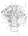
- FIG. 1 shows a schematic view of a gas turbine engine having a multi-stage planetary gearbox incorporating the present invention.
- FIG. 2 shows a cross sectional detail view of the planetary gearbox in FIG. 1 .
- FIG. 3 shows a perspective view of the torque transfer device according to the present invention.
- FIG. 4 a shows a perspective view of a planetary carrier in accordance with an alternate embodiment of the present invention.
- FIG. 4 b shows a front elevation view of the planetary carrier of FIG. 4 a.
- FIG. 5 shows a perspective view of the coupling adapter element of FIG. 3 .
- FIG. 6 shows a perspective exploded view of the torque transfer assembly of the present invention.
- a turboprop gas turbine engine 10 generally having a power plant 14 and a reduction gearbox 12 .
- the engine power plant 14 includes a compressor section 16 , combustion chamber 18 , and a turbine section 20 .
- Air inlets 22 permit air to be drawn into the gas generator and, following power withdrawal by the turbine section, exhaust ducts 24 provide an engine exhaust gas outlet.
- the compressed air is then fed to the combustion chamber 18 where it is mixed with fuel and ignited.
- the hot gas then expands through the turbine section 20 , comprised of a compressor turbine 23 which drives the compressor 18 and the accessories through accessory gearbox 15 , and the power turbine section 25 , which is mechanically independent from the compressor turbine 23 , drives the propeller shaft 29 by means of the planetary reduction gearbox 12 .
- Planetary or epicyclic gearboxes are well known in turboprop applications, and generally comprise a sun gear, a ring gear, and at least two planet gears supported by a planetary carrier, all of which are described in further detail below.
- the hot gas is then discharged to the atmosphere through exhaust ducts 24 .
- the planetary reduction gearbox 12 includes a first reduction stage 26 and a second reduction stage 28 which drive a propeller (not shown), fastened to propeller flange 30 , through propeller shaft 29 .
- the first reduction stage 26 receives input from the power plant through power turbine output shaft 34 which drives the first stage sun gear 32 .
- the first stage outer ring gear 36 is held stationary within the gearbox casing, and a plurality of planet gears 38 are supported within ring gear 36 by a torque transfer planetary carrier assembly 40 , comprised of a first stage planetary carrier 42 and coupling adapter 44 .
- Each planet gear 38 is rotatably mounted in the planetary carrier 42 about an axis 39 , as describe further below, and is in meshing engagement with both the sun gear 32 and the outer ring gear 36 .
- the drive shaft 34 , sun gear 32 , ring gear 36 , and planetary carrier 42 are all concentric about, and both the sun gear 32 and planetary carrier 42 are adapted to rotate about, a central axis 37 .
- Each planet gear 38 has its own individual axis of rotation 39 , about which each rotates, and together are thereby adapted to rotate the planetary carrier 42 about the central axis 37 when driven by shaft 34 through sun gear 32 .
- the coupling adapter 44 is fastened to, and is therefore adapted to rotate with, the first stage carrier 42 and serves to transfer torque to the second reduction stage 28 of the gearbox as described below.
- the second stage 28 operates substantially the same as the first stage, with modifications apparent to those skilled in the art, and thus will only be described briefly here.
- the second stage 28 comprises a central second stage sun gear 56 supported within the adapter 44 , which is in meshing engagement with a plurality of second stage planet gears 60 which rotate within a stationary second stage outer ring gear 58 .
- the second stage planet gears 60 rotate a second stage planetary carrier 62 which provides output torque to the propeller shaft 29 .
- the second stage sun gear 56 and planetary carrier 62 also rotate about the central axis 37 of the reduction gearbox, and second stage planet gears 60 rotate about their individual axes of rotation 59 .
- the torque transfer planetary carrier assembly 40 generally comprises the first stage planetary carrier 42 and the coupling adapter 44 .
- the planet gears 38 are each rotatably mounted in the planetary carrier 42 on axles 41 between planet gear brackets 46 defined in two radially extending carrier plates 48 a and 48 b , perpendicular to central axis 37 and having axle openings 49 therein.
- the carrier plates comprise an upstream plate 48 a and a downstream plate 48 b , preferably integrally joined to one another.
- the planet gear axle openings 49 and the individual axes of rotation 39 are preferably radially and circumferentially equidistantly spaced about central axis 37 . Therefore, in a preferred embodiment having three planet gears 38 , the individual axes of rotation 39 are spaced 120° apart around central axis 37 .
- the mounting pads 50 are axially located intermediate the upstream and downstream plates, 48 a and 48 b respectively, of the planetary carrier 40 , and preferably located at or near the midpoint therebetween. These can be located axially anywhere between the carrier plates to balance the twist occurring between the plates resulting from the deformation of the mounting pads under load.
- the coupling adapter 44 has an equal number of legs 52 extending therefrom and adapted to correspond to and be mated with the mounting pads 50 of the carrier 42 .
- the coupling adapter 44 also comprises a first stage output spline 54 having internal gear teeth 55 adapted to mesh with and transfer torque to another splined component, which in this case, as shown in FIG. 2, is a second stage sun gear 56 .
- this splined component receiving torque output would be replace with a propeller shaft connection means, as would easily be understood by one skilled in the art. Nominally, twist between plates will be completely removed when the carrier and adapter meet at the midpoint between the two plates, however slight adjustments of the placement may be required to balance local moments created around the pin 57 .
- drive shaft 34 rotates sun gear 32 to drive planet gears 38 .
- the planetary carrier 42 is driven via a load transfer through the planet axles 41 to plates 48 a and 48 b .
- Pins 57 pass the load from carrier pads 50 to adapter legs 52 to rotatingly drive the coupling adapter 42 at a reduced speed relative to shaft input drive 34 . Further speed reduction is achieved through the second reduction stage 28 .
- the configuration of the link between the carrier and the coupling adapter is such that no substantially relative twist between the upstream and downstream plates 48 a and 48 b of the planetary carrier occurs. Therefore, no torsional deflection of the planetary carrier occurs, as the torque input is transferred directly to the adapter 44 by the pads on carrier 42 . Thus, a differential torsional load across the planet gear axles 41 , is avoided.
- the location of the interface between the carrier 42 and the adapter 44 i.e. pads 50 and legs 52 ) intermediate the ends of axles 41 of the planet gears 38 (and preferably approximately midway therebetween), assists in removing differential torque loading across the gear axles, and therefore assists in reducing or eliminating twist in the planetary carrier 42 . Improved gear alignment beneficially results.
Landscapes
- Engineering & Computer Science (AREA)
- General Engineering & Computer Science (AREA)
- Mechanical Engineering (AREA)
- Chemical & Material Sciences (AREA)
- Combustion & Propulsion (AREA)
- Retarders (AREA)
- General Details Of Gearings (AREA)
- Arrangement And Driving Of Transmission Devices (AREA)
Abstract
A torque transfer assembly adapted for use in a planetary gear train is provided. The torque transfer assembly comprises generally a planetary carrier and a torque transfer coupling adapter. The planetary carrier is adapted to rotatably support the plurality of planet gears between a first and second planes. The planetary carrier also has a first connecting member extending therefrom. The torque transfer coupling adapter is disposed concentrically and rotatably with the planetary carrier, and has a central torque output element and a second connecting member extending from it. The second connecting member is adapted to be engaged with the first connecting member to structurally join the coupling adapter and the planetary carrier, the first and second connecting members being structurally joined together between the first and second planes.
Description
The present invention relates to epicyclic gearboxes, and more particularly, to a planet gear carrier in an epicyclic gearbox.
Epicyclic or planetary gearboxes are frequently used in gas turbine engines for their compact designs and efficient high gear reduction capabilities. Planetary gear trains are well known, and are generally comprised of three gear train elements: a central sun gear, an outer ring gear with internal gear teeth, and a plurality of planet gears supported by a planet carrier between and in meshing engagement with both the sun gear and the ring gear. All three gear train elements share a common longitudinal central axis, about which at least two of them rotate. An advantage of planetary gear trains is their versatility. A rotary input can be connected to any one of the three elements. Holding one of the remaining two elements stationary with respect to the other two, permits the third to serve as an output.
In gas turbine engine applications, where a speed reduction transmission is required, the central sun gear generally provides rotary input from the powerplant, and the outer ring gear is held stationary. The planet gear carrier therefore provides torque output at a reduced rotational speed.
However, certain shortcomings do exist with planetary drive trains. For example, as with many mechanical elements that transfer torque, a small but nevertheless significant amount of torsional deflection commonly occurs due to the elasticity of the material of the carrier, as a result of twist between upstream and downstream plates of the planetary gear carrier, when the gear train is under load. The plates of the planet gear carrier twist relative to one another around the central axis, causing the axles of the planet gears to lose parallelism with the central axis of the planetary carrier. This torsional deflection results in misalignment at gear train journal bearings and at the gear teeth mesh point, which leads to efficiency losses and reduced life of the parts. Additionally, increased oil flow is required to the journal bearings to compensate for the misalignments caused by torsional deflections of the planet carrier plates.
Attempts to address this problem of planetary carrier torsional deflection are known. U. S. Pat. No. 5,466,198 issued Nov. 14, 1995 to McKibbin et al., for example, clearly sets out the problem and proposes a planetary gear train drive system which isolates the planetary carrier from torsional deflections. A torque frame or torque transfer structure is connected to a rotating load, such as a bladed propulsor. Pivotal joints, circumferentially disposed with respect to the carrier, each pivotable about a radial axis, connect axially extending arms of a torque frame to the planetary carrier. The pivotal joints, which are vital to the invention of McKibbin et al., permit the planetary carrier to be isolated from torsional deflections. While McKibbin et al. do provide a device that eliminates planetary carrier torsional deflections, the planetary carrier system disclosed is of significant complexity. Both a low number of parts and low weight are characteristics vital in aircraft applications. Also, added parts, especially involving pivotable joints, increases the possibility of reliability problems.
Therefore, there remains a need for a simple, compact, device capable of transferring torque while eliminating twist within a planetary carrier.
It is an object of the present invention to provide an improved planetary gear train.
It is an object of the present invention to provide a torque transfer device for use in a planetary gear train.
It is another object of the present invention to provide a planetary carrier capable of torque transfer with minimal twist occurring between the upstream and downstream plates of a planetary carrier.
Therefore, in accordance with the present invention, there is provided a torque transfer assembly adapted for use in a planetary gear train, the gear train including a sun gear rotatable about an axially extending central axis, a concentric stationary outer ring gear, and a plurality of planet gears mechanically intermediate said sun gear and said ring gear and in meshing engagement therewith, the plurality of planet gears adapted for receiving torque input from the sun gear, said torque transfer assembly comprising: a planetary carrier, rotatable about said axially extending central axis and adapted to rotatably support said plurality of planet gears on a plurality of axles between first and second axle ends, said first and second axle ends defining first and second planes respectively, said plurality of axles being parallel to the central axis and the first and second planes being perpendicular to the central axis, the planet gears being circumferentially located on the planetary carrier about the central axis, the carrier having a first connecting member extending therefrom; and a torque transfer coupling adapter, disposed concentrically with said planetary carrier and rotatable therewith, said torque transfer coupling adapter having a central torque output element and a second connecting member extending therefrom, said second connecting member adapted to be engaged with said first connecting member to structurally join the coupling adapter and the planetary carrier, said first and second connecting members being structurally joined together between said first and second planes.
Further features and advantages of the present invention will become apparent from the following detailed description, taken in combination with the appended drawings, in which:
FIG. 1 shows a schematic view of a gas turbine engine having a multi-stage planetary gearbox incorporating the present invention.
FIG. 2 shows a cross sectional detail view of the planetary gearbox in FIG. 1.
FIG. 3 shows a perspective view of the torque transfer device according to the present invention.
FIG. 4a shows a perspective view of a planetary carrier in accordance with an alternate embodiment of the present invention.
FIG. 4b shows a front elevation view of the planetary carrier of FIG. 4a.
FIG. 5 shows a perspective view of the coupling adapter element of FIG. 3.
FIG. 6 shows a perspective exploded view of the torque transfer assembly of the present invention.
Referring to FIG. 1, a turboprop gas turbine engine 10 generally having a power plant 14 and a reduction gearbox 12. The engine power plant 14 includes a compressor section 16, combustion chamber 18, and a turbine section 20. Air inlets 22 permit air to be drawn into the gas generator and, following power withdrawal by the turbine section, exhaust ducts 24 provide an engine exhaust gas outlet.
The operation of such a gas turbine engine is well known, and occurs generally as follows by means of example only. Air enters the engine through the inlet 17 and is compressed by the compressor section 16, in this case comprising axial flow compressors 19 and a centrifugal compressor 21. The compressed air is then fed to the combustion chamber 18 where it is mixed with fuel and ignited. The hot gas then expands through the turbine section 20, comprised of a compressor turbine 23 which drives the compressor 18 and the accessories through accessory gearbox 15, and the power turbine section 25, which is mechanically independent from the compressor turbine 23, drives the propeller shaft 29 by means of the planetary reduction gearbox 12. Planetary or epicyclic gearboxes are well known in turboprop applications, and generally comprise a sun gear, a ring gear, and at least two planet gears supported by a planetary carrier, all of which are described in further detail below. The hot gas is then discharged to the atmosphere through exhaust ducts 24.
In the exemplary embodiment, the planetary reduction gearbox 12 includes a first reduction stage 26 and a second reduction stage 28 which drive a propeller (not shown), fastened to propeller flange 30, through propeller shaft 29.
Referring now to FIG. 2, the reduction gearbox 12 will now be described in more detail. The first reduction stage 26 receives input from the power plant through power turbine output shaft 34 which drives the first stage sun gear 32. The first stage outer ring gear 36 is held stationary within the gearbox casing, and a plurality of planet gears 38 are supported within ring gear 36 by a torque transfer planetary carrier assembly 40, comprised of a first stage planetary carrier 42 and coupling adapter 44. Each planet gear 38 is rotatably mounted in the planetary carrier 42 about an axis 39, as describe further below, and is in meshing engagement with both the sun gear 32 and the outer ring gear 36. The drive shaft 34, sun gear 32, ring gear 36, and planetary carrier 42 are all concentric about, and both the sun gear 32 and planetary carrier 42 are adapted to rotate about, a central axis 37. Each planet gear 38 has its own individual axis of rotation 39, about which each rotates, and together are thereby adapted to rotate the planetary carrier 42 about the central axis 37 when driven by shaft 34 through sun gear 32.
The coupling adapter 44 is fastened to, and is therefore adapted to rotate with, the first stage carrier 42 and serves to transfer torque to the second reduction stage 28 of the gearbox as described below. The second stage 28 operates substantially the same as the first stage, with modifications apparent to those skilled in the art, and thus will only be described briefly here. The second stage 28 comprises a central second stage sun gear 56 supported within the adapter 44, which is in meshing engagement with a plurality of second stage planet gears 60 which rotate within a stationary second stage outer ring gear 58. The second stage planet gears 60 rotate a second stage planetary carrier 62 which provides output torque to the propeller shaft 29. The second stage sun gear 56 and planetary carrier 62 also rotate about the central axis 37 of the reduction gearbox, and second stage planet gears 60 rotate about their individual axes of rotation 59.
Referring now to FIGS. 3, 4 a, 4 b, 5 and 6, the torque transfer planetary carrier assembly 40 generally comprises the first stage planetary carrier 42 and the coupling adapter 44. The planet gears 38 are each rotatably mounted in the planetary carrier 42 on axles 41 between planet gear brackets 46 defined in two radially extending carrier plates 48 a and 48 b, perpendicular to central axis 37 and having axle openings 49 therein. The carrier plates comprise an upstream plate 48 a and a downstream plate 48 b, preferably integrally joined to one another. The planet gear axle openings 49 and the individual axes of rotation 39 are preferably radially and circumferentially equidistantly spaced about central axis 37. Therefore, in a preferred embodiment having three planet gears 38, the individual axes of rotation 39 are spaced 120° apart around central axis 37.
A plurality of mounting pads 50 extending from the planetary carrier 42 preferably circumferentially intermediate each planet gear individual axis of rotation 39. The mounting pads 50 are axially located intermediate the upstream and downstream plates, 48 a and 48 b respectively, of the planetary carrier 40, and preferably located at or near the midpoint therebetween. These can be located axially anywhere between the carrier plates to balance the twist occurring between the plates resulting from the deformation of the mounting pads under load. The coupling adapter 44 has an equal number of legs 52 extending therefrom and adapted to correspond to and be mated with the mounting pads 50 of the carrier 42. Mating holes 53 are provided for connection, and the two elements are preferably mounted together using press fit pins 57 and a threaded nut, though other connection means are possible. In the exemplary embodiment, the coupling adapter 44 also comprises a first stage output spline 54 having internal gear teeth 55 adapted to mesh with and transfer torque to another splined component, which in this case, as shown in FIG. 2, is a second stage sun gear 56. In a single stage planetary gearbox, this splined component receiving torque output would be replace with a propeller shaft connection means, as would easily be understood by one skilled in the art. Nominally, twist between plates will be completely removed when the carrier and adapter meet at the midpoint between the two plates, however slight adjustments of the placement may be required to balance local moments created around the pin 57.
In use, drive shaft 34 rotates sun gear 32 to drive planet gears 38. As planet gears 38 rotate within stationary ring gear 36, the planetary carrier 42 is driven via a load transfer through the planet axles 41 to plates 48 a and 48 b. Pins 57 pass the load from carrier pads 50 to adapter legs 52 to rotatingly drive the coupling adapter 42 at a reduced speed relative to shaft input drive 34. Further speed reduction is achieved through the second reduction stage 28.
The configuration of the link between the carrier and the coupling adapter is such that no substantially relative twist between the upstream and downstream plates 48 a and 48 b of the planetary carrier occurs. Therefore, no torsional deflection of the planetary carrier occurs, as the torque input is transferred directly to the adapter 44 by the pads on carrier 42. Thus, a differential torsional load across the planet gear axles 41, is avoided. The location of the interface between the carrier 42 and the adapter 44 (i.e. pads 50 and legs 52) intermediate the ends of axles 41 of the planet gears 38 (and preferably approximately midway therebetween), assists in removing differential torque loading across the gear axles, and therefore assists in reducing or eliminating twist in the planetary carrier 42. Improved gear alignment beneficially results.
The embodiment of the invention described above is intended to be exemplary only. For example, in the preferred embodiment three planet gears are used, however another number of planet gears can be used. Additionally, the torque transfer assembly can be applied to a single reduction stage, wherein the coupling adapter could drive the propeller shaft directly. One skilled in the art will appreciate that the present invention also has application well beyond the gas turbine engine example described. The scope of the invention is therefore intended to be limited solely by the scope of the appended claims.
Claims (14)
1. A torque transfer assembly adapted for use in a planetary gear train, the gear train including a sun gear rotatable about an axially extending central axis, a concentric outer ring gear, and a plurality of planet gears mechanically intermediate said sun gear and said ring gear and in meshing engagement therewith, the plurality of planet gears adapted for receiving torque input from the sun gear, said torque transfer assembly comprising:
a planetary carrier rotatable about said axially extending central axis and adapted to rotatably support said plurality of planet gears on a plurality of axles between first and second axle ends, said first and second axle ends defining first and second planes respectively, said plurality of axles being parallel to the central axis and the first and second planes being perpendicular to the central axis, the planet gears being circumferentially located on the planetary carrier about the central axis, the carrier having a first connecting member extending therefrom; and
a torque transfer coupling adapter disposed concentrically with said planetary carrier and rotatable therewith, said torque transfer coupling adapter having a central torque output element and a second connecting member extending therefrom, said second connecting member adapted to be engaged with said first connecting member to structurally join the coupling adapter and the planetary carrier, said first and second connecting members being structurally joined together between said first and second planes.
2. The torque transfer device as defined in claim 1 , wherein said torque transfer coupling adapter is removably engaged with said planetary carrier.
3. The torque transfer device as defined in claim 1 , wherein the first and second connecting members engage one another at approximately a midpoint between the first and second planes.
4. The torque transfer device as defined in claim 1 , wherein the torque transfer coupling adapter and the planetary carrier are engaged together only at the first and second connecting members.
5. The torque transfer device as defined in claim 1 , wherein the first connecting member comprises a plurality of first connecting elements and wherein the second connecting member comprises an equal number of second connecting elements.
6. The torque transfer device as defined in claim 5 , wherein the second connecting elements are leg elements extending from the central torque output element of the torque transfer coupling adapter, and wherein the first connecting elements comprise a plurality of mounting locations adapted to receive the leg elements.
7. The torque transfer device as defined in claim 6 , wherein the leg elements are disposed intermediately between said planet gears.
8. The torque transfer device as defined in claim 1 , wherein said central torque output element of said torque transfer coupling adapter comprises gear teeth adapted for meshed engagement with a driven output.
9. The torque transfer device as defined in claim 8 , wherein said driven output is a propeller shaft.
10. The torque transfer device as defined in claim 8 , wherein said driven output is an input spline for a subsequent stage of said planetary gear train.
11. The torque transfer device as defined in claim 2 , wherein said torque transfer coupling adapter and said planetary carrier are engaged by fasteners.
12. The torque transfer device as defined in claim 11 , wherein said fasteners are radially disposed outwardly of individual axis of rotation of said plurality of planet gears.
13. The torque transfer device as defined in claim 1 , wherein said first and second connecting members are integral.
14. The torque transfer device as defined in claim 1 , wherein said planetary carrier comprises axially spaced apart upstream and downstream plates supporting said plurality of axles therebetween, said upstream and downstream plates respectively defining third and fourth planes substantially perpendicular to said central axis, and said first and second connecting members being structurally joined together between said third and fourth planes.
Priority Applications (14)
| Application Number | Priority Date | Filing Date | Title |
|---|---|---|---|
| US10/017,152 US6663530B2 (en) | 2001-12-14 | 2001-12-14 | Zero twist carrier |
| PCT/CA2002/001704 WO2003052299A1 (en) | 2001-12-14 | 2002-11-07 | Zero twist carrier |
| RU2004121779/11A RU2004121779A (en) | 2001-12-14 | 2002-11-07 | TORQUE TRANSMISSION DEVICE FOR PLANETARY GEAR |
| JP2003553153A JP2005513370A (en) | 2001-12-14 | 2002-11-07 | Untwisted carrier |
| CA2466562A CA2466562C (en) | 2001-12-14 | 2002-11-07 | Zero twist carrier |
| EP02774194A EP1454082A1 (en) | 2001-12-14 | 2002-11-07 | Zero twist carrier |
| DE60236620T DE60236620D1 (en) | 2001-12-14 | 2002-12-13 | PLANET CARRIER WITH REDUCED DEFLECTION |
| RU2004121777/11A RU2004121777A (en) | 2001-12-14 | 2002-12-13 | TORQUE TRANSMISSION DEVICE FOR EPICYCLIC GEARS AND DRIVE GEAR ASSEMBLY (OPTIONS) |
| PCT/CA2002/001925 WO2003052300A1 (en) | 2001-12-14 | 2002-12-13 | Reduced twist carrier |
| CA2469631A CA2469631C (en) | 2001-12-14 | 2002-12-13 | Reduced twist carrier |
| JP2003553154A JP2005513371A (en) | 2001-12-14 | 2002-12-13 | Carrier with reduced twist |
| US10/318,220 US6855089B2 (en) | 2001-12-14 | 2002-12-13 | Reduced twist carrier |
| EP02787252A EP1461544B1 (en) | 2001-12-14 | 2002-12-13 | Reduced twist carrier |
| US11/029,393 US7223197B2 (en) | 2001-12-14 | 2005-01-06 | Reduced twist carrier |
Applications Claiming Priority (1)
| Application Number | Priority Date | Filing Date | Title |
|---|---|---|---|
| US10/017,152 US6663530B2 (en) | 2001-12-14 | 2001-12-14 | Zero twist carrier |
Related Child Applications (2)
| Application Number | Title | Priority Date | Filing Date |
|---|---|---|---|
| US10/318,220 Continuation-In-Part US6855089B2 (en) | 2001-12-14 | 2002-12-13 | Reduced twist carrier |
| US11/029,393 Continuation-In-Part US7223197B2 (en) | 2001-12-14 | 2005-01-06 | Reduced twist carrier |
Publications (2)
| Publication Number | Publication Date |
|---|---|
| US20030114267A1 US20030114267A1 (en) | 2003-06-19 |
| US6663530B2 true US6663530B2 (en) | 2003-12-16 |
Family
ID=21781009
Family Applications (3)
| Application Number | Title | Priority Date | Filing Date |
|---|---|---|---|
| US10/017,152 Expired - Lifetime US6663530B2 (en) | 2001-12-14 | 2001-12-14 | Zero twist carrier |
| US10/318,220 Expired - Lifetime US6855089B2 (en) | 2001-12-14 | 2002-12-13 | Reduced twist carrier |
| US11/029,393 Expired - Lifetime US7223197B2 (en) | 2001-12-14 | 2005-01-06 | Reduced twist carrier |
Family Applications After (2)
| Application Number | Title | Priority Date | Filing Date |
|---|---|---|---|
| US10/318,220 Expired - Lifetime US6855089B2 (en) | 2001-12-14 | 2002-12-13 | Reduced twist carrier |
| US11/029,393 Expired - Lifetime US7223197B2 (en) | 2001-12-14 | 2005-01-06 | Reduced twist carrier |
Country Status (7)
| Country | Link |
|---|---|
| US (3) | US6663530B2 (en) |
| EP (2) | EP1454082A1 (en) |
| JP (2) | JP2005513370A (en) |
| CA (2) | CA2466562C (en) |
| DE (1) | DE60236620D1 (en) |
| RU (2) | RU2004121779A (en) |
| WO (2) | WO2003052299A1 (en) |
Cited By (36)
| Publication number | Priority date | Publication date | Assignee | Title |
|---|---|---|---|---|
| US20040077455A1 (en) * | 2002-03-05 | 2004-04-22 | Huber David P. | Pinion carrier for planetary gear train and method of making same |
| US20050026745A1 (en) * | 2003-07-29 | 2005-02-03 | Lazar Mitrovic | Compact epicyclic gear carrier |
| US20060205560A1 (en) * | 2005-03-10 | 2006-09-14 | Transform Automotive Llc | Transmission unitary shell output carrier and ring gear |
| US20100263497A1 (en) * | 2009-04-19 | 2010-10-21 | Sawyer George M | Bolt holder tool |
| US8297917B1 (en) | 2011-06-08 | 2012-10-30 | United Technologies Corporation | Flexible support structure for a geared architecture gas turbine engine |
| US20130053202A1 (en) * | 2011-08-26 | 2013-02-28 | General Electric Company | Journal bearing for use in epicyclical gearbox and method of facilitating hydrodynamic oil flow in the journal bearing |
| US20130319001A1 (en) * | 2012-05-31 | 2013-12-05 | John R. Otto | Turbine gear assembly support having symmetrical removal features |
| US8684303B2 (en) | 2008-06-02 | 2014-04-01 | United Technologies Corporation | Gas turbine engine compressor arrangement |
| US8727935B2 (en) | 2012-07-30 | 2014-05-20 | United Technologies Corporation | Fan drive gear system torque frame pin retainer |
| US8747055B2 (en) | 2011-06-08 | 2014-06-10 | United Technologies Corporation | Geared architecture for high speed and small volume fan drive turbine |
| US8756908B2 (en) | 2012-05-31 | 2014-06-24 | United Technologies Corporation | Fundamental gear system architecture |
| US8770922B2 (en) | 2011-06-08 | 2014-07-08 | United Technologies Corporation | Flexible support structure for a geared architecture gas turbine engine |
| US8777793B2 (en) | 2011-04-27 | 2014-07-15 | United Technologies Corporation | Fan drive planetary gear system integrated carrier and torque frame |
| US8814503B2 (en) | 2011-06-08 | 2014-08-26 | United Technologies Corporation | Flexible support structure for a geared architecture gas turbine engine |
| US8900083B2 (en) | 2011-04-27 | 2014-12-02 | United Technologies Corporation | Fan drive gear system integrated carrier and torque frame |
| US9133729B1 (en) | 2011-06-08 | 2015-09-15 | United Technologies Corporation | Flexible support structure for a geared architecture gas turbine engine |
| US9239012B2 (en) | 2011-06-08 | 2016-01-19 | United Technologies Corporation | Flexible support structure for a geared architecture gas turbine engine |
| US9267389B2 (en) | 2012-06-05 | 2016-02-23 | United Technologies Corporation | Geared architecture carrier torque frame assembly |
| US9410608B2 (en) | 2011-06-08 | 2016-08-09 | United Technologies Corporation | Flexible support structure for a geared architecture gas turbine engine |
| US9840969B2 (en) | 2012-05-31 | 2017-12-12 | United Technologies Corporation | Gear system architecture for gas turbine engine |
| US9863326B2 (en) | 2013-03-12 | 2018-01-09 | United Technologies Corporation | Flexible coupling for geared turbine engine |
| EP3361122A1 (en) | 2017-02-10 | 2018-08-15 | Pratt & Whitney Canada Corp. | Planetary gearbox for gas turbine engine |
| US10119465B2 (en) | 2015-06-23 | 2018-11-06 | United Technologies Corporation | Geared turbofan with independent flexible ring gears and oil collectors |
| US10221770B2 (en) | 2012-05-31 | 2019-03-05 | United Technologies Corporation | Fundamental gear system architecture |
| US10451004B2 (en) | 2008-06-02 | 2019-10-22 | United Technologies Corporation | Gas turbine engine with low stage count low pressure turbine |
| EP3572690A1 (en) | 2018-05-25 | 2019-11-27 | Pratt & Whitney Canada Corp. | Planetary gearbox having compliant journal bearings |
| US10662879B2 (en) | 2017-08-08 | 2020-05-26 | Pratt & Whitney Canada Corp. | Epicyclic gear stage |
| US10760677B2 (en) | 2018-01-31 | 2020-09-01 | Pratt & Whitney Canada Corp. | Epicyclic gear train with balanced carrier stiffness |
| US10927944B2 (en) | 2018-01-26 | 2021-02-23 | Pratt & Whitney Canada Corp. | Compact, twist controlled planet carrier and epicyclic gear train having same |
| EP3859134A1 (en) | 2020-01-28 | 2021-08-04 | Pratt & Whitney Canada Corp. | Planetary gearbox for gas turbine engine |
| US11598407B1 (en) | 2022-02-16 | 2023-03-07 | Pratt & Whitney Canada Corp. | Epicyclic gear train of aircraft powerplant |
| US11970984B2 (en) | 2012-04-02 | 2024-04-30 | Rtx Corporation | Gas turbine engine with power density range |
| EP4459153A1 (en) | 2023-05-05 | 2024-11-06 | Pratt & Whitney Canada Corp. | Reduction gearbox for gas turbine engine |
| EP4459114A1 (en) | 2023-05-05 | 2024-11-06 | Pratt & Whitney Canada Corp. | Reduction gearbox for gas turbine engine with lubrication control system |
| EP4459152A1 (en) | 2023-05-05 | 2024-11-06 | Pratt & Whitney Canada Corp. | Reduction gearbox for gas turbine engine |
| US12366179B2 (en) | 2012-01-31 | 2025-07-22 | Rtx Corporation | Gas turbine engine with high speed low pressure turbine section and bearing support features |
Families Citing this family (60)
| Publication number | Priority date | Publication date | Assignee | Title |
|---|---|---|---|---|
| US6758598B2 (en) | 2002-08-23 | 2004-07-06 | Pratt & Whitney Canada Corp. | Integrated oil transfer sleeve and bearing |
| WO2004085880A1 (en) * | 2003-03-25 | 2004-10-07 | Klaus Plath | Gearbox device |
| JP4576993B2 (en) * | 2004-11-24 | 2010-11-10 | トヨタ自動車株式会社 | An annular gear and a planetary gear unit including the gear |
| EP1868834B1 (en) * | 2005-04-01 | 2009-10-28 | Bonfiglioli Riduttori S.p.A. | Drive system for dual wheels, particularly of the type used on road rollers |
| US7591754B2 (en) * | 2006-03-22 | 2009-09-22 | United Technologies Corporation | Epicyclic gear train integral sun gear coupling design |
| DE102006049229A1 (en) * | 2006-10-18 | 2008-04-30 | Lucas Automotive Gmbh | Electric parking brake actuator with planetary gear |
| US20080314968A1 (en) * | 2007-05-23 | 2008-12-25 | Maher Patrick R | System and Method for Capturing and Managing Personal Documents and Information |
| JP4901611B2 (en) * | 2007-07-04 | 2012-03-21 | 本田技研工業株式会社 | Aircraft reducer |
| JP2009185973A (en) * | 2008-02-08 | 2009-08-20 | Yamaha Motor Co Ltd | A planetary gear device carrier, a planetary gear device including the carrier, and an outboard motor including the planetary gear device. |
| US8480527B2 (en) * | 2008-08-27 | 2013-07-09 | Rolls-Royce Corporation | Gearing arrangement |
| US8439631B2 (en) * | 2008-09-05 | 2013-05-14 | Rolls-Royce Corporation | Shaft coupling arrangement |
| US9121351B2 (en) * | 2008-10-30 | 2015-09-01 | Rolls-Royce North American Technologies, Inc. | Gas turbine engine accessory system |
| US8517672B2 (en) * | 2010-02-23 | 2013-08-27 | General Electric Company | Epicyclic gearbox |
| US8172717B2 (en) * | 2011-06-08 | 2012-05-08 | General Electric Company | Compliant carrier wall for improved gearbox load sharing |
| US9021778B2 (en) | 2011-06-28 | 2015-05-05 | United Technologies Corporation | Differential gear system with carrier drive |
| JP2013019490A (en) * | 2011-07-12 | 2013-01-31 | Ricoh Co Ltd | Drive device, and image forming device |
| US8899916B2 (en) | 2011-08-30 | 2014-12-02 | United Technologies Corporation | Torque frame and asymmetric journal bearing for fan drive gear system |
| US8935913B2 (en) * | 2012-01-31 | 2015-01-20 | United Technologies Corporation | Geared turbofan gas turbine engine architecture |
| US9222417B2 (en) | 2012-01-31 | 2015-12-29 | United Technologies Corporation | Geared turbofan gas turbine engine architecture |
| US20130192191A1 (en) | 2012-01-31 | 2013-08-01 | Frederick M. Schwarz | Gas turbine engine with high speed low pressure turbine section and bearing support features |
| US20160130949A1 (en) * | 2012-01-31 | 2016-05-12 | United Technologies Corporation | Low noise turbine for geared turbofan engine |
| US20150345426A1 (en) | 2012-01-31 | 2015-12-03 | United Technologies Corporation | Geared turbofan gas turbine engine architecture |
| US8961112B2 (en) * | 2012-03-26 | 2015-02-24 | United Technologies Corporation | Torque frame bushing arrangement for gas turbine engine fan drive gear system |
| US8790075B2 (en) | 2012-03-30 | 2014-07-29 | United Technologies Corporation | Gas turbine engine geared architecture axial retention arrangement |
| US20130255274A1 (en) * | 2012-04-02 | 2013-10-03 | Daniel Bernard Kupratis | Geared architecture with speed change device for gas turbine engine |
| DE102012012097A1 (en) * | 2012-06-18 | 2013-12-19 | Robert Bosch Gmbh | Planet carrier of a planetary gear |
| US9273737B2 (en) | 2012-08-07 | 2016-03-01 | Ford Global Technologies, Llc | Integrated pinion carrier and overrunning element race |
| WO2014099087A2 (en) * | 2012-09-28 | 2014-06-26 | United Technologies Corporation | Method of assembly for gas turbine fan drive gear system |
| PL3004598T3 (en) * | 2013-06-06 | 2020-03-31 | United Technologies Corporation | Spline ring for a fan drive gear flexible support |
| FR3011901B1 (en) * | 2013-10-10 | 2017-02-10 | Hispano-Suiza | SATELLITE CARRIER FOR AN EPICYCLOIDAL TRAIN SPEED REDUCER |
| DE102014206977A1 (en) * | 2014-04-11 | 2015-10-15 | Schaeffler Technologies AG & Co. KG | Weight-optimized planet carrier |
| US9709136B2 (en) * | 2014-06-10 | 2017-07-18 | The Boeing Company | Aircraft and planetary gear systems |
| CN104021720B (en) * | 2014-06-10 | 2016-05-25 | 上海理工大学 | Cyclic train experiment teaching aid |
| US9828109B2 (en) | 2014-07-23 | 2017-11-28 | Pratt & Whitney Canada Corp. | Apparatus and methods for powering an electrical device associated with an aircraft rotor |
| US10094293B2 (en) | 2014-08-22 | 2018-10-09 | Pratt & Whitney Canada Corp. | In flight restart system and method for free turbine engine |
| US9695710B2 (en) | 2014-09-08 | 2017-07-04 | United Technologies Corporation | Oil transfer bearing |
| CN104747656A (en) * | 2015-03-18 | 2015-07-01 | 成都飞机工业(集团)有限责任公司 | Speed increasing device |
| US10072582B2 (en) * | 2016-04-28 | 2018-09-11 | General Electric Company | Integral offset oil tank for inline accessory gearbox |
| US10813807B2 (en) * | 2016-06-29 | 2020-10-27 | Stryker Corporation | Patient support systems with hollow rotary actuators |
| US11415063B2 (en) | 2016-09-15 | 2022-08-16 | Pratt & Whitney Canada Corp. | Reverse-flow gas turbine engine |
| US10883424B2 (en) | 2016-07-19 | 2021-01-05 | Pratt & Whitney Canada Corp. | Multi-spool gas turbine engine architecture |
| JP6867123B2 (en) * | 2016-08-12 | 2021-04-28 | 川崎重工業株式会社 | Planetary gear speed reducer |
| US10465611B2 (en) | 2016-09-15 | 2019-11-05 | Pratt & Whitney Canada Corp. | Reverse flow multi-spool gas turbine engine with aft-end accessory gearbox drivingly connected to both high pressure spool and low pressure spool |
| US11035293B2 (en) | 2016-09-15 | 2021-06-15 | Pratt & Whitney Canada Corp. | Reverse flow gas turbine engine with offset RGB |
| US10815899B2 (en) * | 2016-11-15 | 2020-10-27 | Pratt & Whitney Canada Corp. | Gas turbine engine accessories arrangement |
| US10808624B2 (en) | 2017-02-09 | 2020-10-20 | Pratt & Whitney Canada Corp. | Turbine rotor with low over-speed requirements |
| US10746188B2 (en) | 2017-03-14 | 2020-08-18 | Pratt & Whitney Canada Corp. | Inter-shaft bearing connected to a compressor boost system |
| US10519871B2 (en) | 2017-05-18 | 2019-12-31 | Pratt & Whitney Canada Corp. | Support assembly for a propeller shaft |
| US11619302B2 (en) * | 2017-06-14 | 2023-04-04 | Dana Automotive Systems Group, Llc | Actuation mechanism |
| DE102017008674A1 (en) * | 2017-09-15 | 2019-03-21 | Rolls-Royce Deutschland Ltd & Co Kg | planetary gear |
| US11225912B2 (en) * | 2018-04-20 | 2022-01-18 | Pratt & Whitney Canada Corp. | Gear assembly for coaxial shafts in gas turbine engine |
| EP4339440A3 (en) | 2018-08-08 | 2024-05-22 | Pratt & Whitney Canada Corp. | Multi-engine system and method |
| US11174916B2 (en) | 2019-03-21 | 2021-11-16 | Pratt & Whitney Canada Corp. | Aircraft engine reduction gearbox |
| US11506081B2 (en) * | 2019-08-23 | 2022-11-22 | Rolls-Royce Corporation | Filtration system for geared turbofan tank |
| US11506080B2 (en) | 2020-10-02 | 2022-11-22 | Pratt & Whitney Canada Corp. | Gas turbine engine probe cooling |
| US11268453B1 (en) | 2021-03-17 | 2022-03-08 | Pratt & Whitney Canada Corp. | Lubrication system for aircraft engine reduction gearbox |
| FR3124565B1 (en) * | 2021-06-24 | 2023-07-14 | Safran Trans Systems | SATELLITE CARRIER FOR AN AIRCRAFT TURBOMACHINE SPEED REDUCER |
| DE102021207527A1 (en) * | 2021-07-15 | 2023-01-19 | Zf Friedrichshafen Ag | Transmission for an integral differential, integral differential and power train |
| US12460706B2 (en) | 2023-12-08 | 2025-11-04 | Pratt & Whitney Canada Corp. | Epicyclic system with bevel attachment for dual-power applications |
| US12460577B2 (en) * | 2024-03-27 | 2025-11-04 | Rtx Corporation | AFT gear based engine with heat recovery system |
Citations (24)
| Publication number | Priority date | Publication date | Assignee | Title |
|---|---|---|---|---|
| GB725364A (en) | 1953-04-14 | 1955-03-02 | Rotary Hoes Ltd | Planetary speed-reduction gearing |
| US3527121A (en) * | 1968-08-26 | 1970-09-08 | Gen Motors Corp | Carrier |
| US3842481A (en) * | 1970-05-15 | 1974-10-22 | Borg Warner Ltd | Method of making planetary carrier assembly |
| GB1420965A (en) | 1971-12-16 | 1976-01-14 | Lohmann & Stolterfoht Ag | Multistage reduction gears |
| US3939736A (en) * | 1973-10-10 | 1976-02-24 | Regie Nationale Des Usines Renault | Planet carrier for a planetary gear train |
| US4129050A (en) * | 1977-04-28 | 1978-12-12 | Toyota Jidosha Kogyo Kabushiki Kaisha | Gear means of an automatic transmission for automobiles |
| US4282776A (en) | 1979-03-29 | 1981-08-11 | Eller Fritz D | Overload protection for transmission system with planetary-gear train |
| US4329130A (en) | 1978-07-03 | 1982-05-11 | Oval Engineering Company Limited | Flow meter with helical toothed rotors having no pulsation and zero contact pressure |
| US4586401A (en) | 1984-04-16 | 1986-05-06 | Chrysler Corporation | Transmission speed sensor arrangement |
| EP0271416A1 (en) * | 1986-11-18 | 1988-06-15 | Ateliers De Mecanique Generale (Societe Anonyme) | Planet carrier |
| US4793214A (en) * | 1985-11-14 | 1988-12-27 | Fichtel & Sachs Ag | Planet wheel carrier |
| US4983152A (en) * | 1989-09-08 | 1991-01-08 | Ingersoll-Rand Company | Planet gear frame assembly |
| US5136197A (en) | 1991-06-25 | 1992-08-04 | Clarence Hallett | Reaction containment drive for power tool |
| US5152726A (en) | 1991-07-01 | 1992-10-06 | General Motors Corporation | Shiftable roller clutch |
| US5237885A (en) | 1990-05-21 | 1993-08-24 | Snap-On Tools Corporation | Ratchet tool |
| US5309714A (en) | 1990-05-21 | 1994-05-10 | Snap-On Tools Corporation | Ratchet tool with exhaust chamber manifold with sound dampening properties |
| EP0618383A1 (en) | 1993-04-01 | 1994-10-05 | Ford Motor Company Limited | Planetary gearset carrier assembly |
| US5466198A (en) | 1993-06-11 | 1995-11-14 | United Technologies Corporation | Geared drive system for a bladed propulsor |
| US5470286A (en) * | 1994-07-29 | 1995-11-28 | General Motors Corporation | Reaction carrier assembly having zero relative pin deflection |
| US5649254A (en) * | 1990-11-14 | 1997-07-15 | Seiko Epson Corporation | Film winding mechanism for a camera |
| US5679089A (en) | 1995-09-14 | 1997-10-21 | The United States Of America As Represented By The Secretary Of The Navy | Bicoupled contrarotating epicyclic gears |
| EP0989316A1 (en) | 1997-06-13 | 2000-03-29 | Unipres Corporation | Torque transmitting member in automotive transmission, method for forming spline teeth, and apparatus for forming the same |
| US6148605A (en) | 1998-03-05 | 2000-11-21 | Societe Nationale D'etude Et De Construction De Moteurs D'aviation "Snecma" | Method and device for reversing the thrust of very high bypass ratio turbojet engines |
| US6422971B1 (en) * | 1999-10-08 | 2002-07-23 | Aisin Aw Co., Ltd. | Planetary carrier |
Family Cites Families (4)
| Publication number | Priority date | Publication date | Assignee | Title |
|---|---|---|---|---|
| JPS5861982A (en) * | 1981-10-07 | 1983-04-13 | Nissan Motor Co Ltd | Production of planetary gear carrier |
| JPS58156773A (en) * | 1982-03-10 | 1983-09-17 | Nissan Motor Co Ltd | Carrier assembly for planetary gear |
| JPH07332475A (en) * | 1994-06-03 | 1995-12-22 | Nissan Motor Co Ltd | Carrier structure of planetary gear unit |
| JPH08270739A (en) * | 1995-03-28 | 1996-10-15 | Nissan Motor Co Ltd | Carrier structure of planetary gear of automatic transmission |
-
2001
- 2001-12-14 US US10/017,152 patent/US6663530B2/en not_active Expired - Lifetime
-
2002
- 2002-11-07 WO PCT/CA2002/001704 patent/WO2003052299A1/en not_active Ceased
- 2002-11-07 CA CA2466562A patent/CA2466562C/en not_active Expired - Lifetime
- 2002-11-07 JP JP2003553153A patent/JP2005513370A/en active Pending
- 2002-11-07 RU RU2004121779/11A patent/RU2004121779A/en unknown
- 2002-11-07 EP EP02774194A patent/EP1454082A1/en not_active Withdrawn
- 2002-12-13 DE DE60236620T patent/DE60236620D1/en not_active Expired - Lifetime
- 2002-12-13 JP JP2003553154A patent/JP2005513371A/en active Pending
- 2002-12-13 CA CA2469631A patent/CA2469631C/en not_active Expired - Lifetime
- 2002-12-13 RU RU2004121777/11A patent/RU2004121777A/en unknown
- 2002-12-13 US US10/318,220 patent/US6855089B2/en not_active Expired - Lifetime
- 2002-12-13 EP EP02787252A patent/EP1461544B1/en not_active Expired - Lifetime
- 2002-12-13 WO PCT/CA2002/001925 patent/WO2003052300A1/en not_active Ceased
-
2005
- 2005-01-06 US US11/029,393 patent/US7223197B2/en not_active Expired - Lifetime
Patent Citations (25)
| Publication number | Priority date | Publication date | Assignee | Title |
|---|---|---|---|---|
| GB725364A (en) | 1953-04-14 | 1955-03-02 | Rotary Hoes Ltd | Planetary speed-reduction gearing |
| US3527121A (en) * | 1968-08-26 | 1970-09-08 | Gen Motors Corp | Carrier |
| US3842481A (en) * | 1970-05-15 | 1974-10-22 | Borg Warner Ltd | Method of making planetary carrier assembly |
| GB1420965A (en) | 1971-12-16 | 1976-01-14 | Lohmann & Stolterfoht Ag | Multistage reduction gears |
| US3939736A (en) * | 1973-10-10 | 1976-02-24 | Regie Nationale Des Usines Renault | Planet carrier for a planetary gear train |
| US4129050A (en) * | 1977-04-28 | 1978-12-12 | Toyota Jidosha Kogyo Kabushiki Kaisha | Gear means of an automatic transmission for automobiles |
| US4329130A (en) | 1978-07-03 | 1982-05-11 | Oval Engineering Company Limited | Flow meter with helical toothed rotors having no pulsation and zero contact pressure |
| US4282776A (en) | 1979-03-29 | 1981-08-11 | Eller Fritz D | Overload protection for transmission system with planetary-gear train |
| US4586401A (en) | 1984-04-16 | 1986-05-06 | Chrysler Corporation | Transmission speed sensor arrangement |
| US4793214A (en) * | 1985-11-14 | 1988-12-27 | Fichtel & Sachs Ag | Planet wheel carrier |
| EP0271416A1 (en) * | 1986-11-18 | 1988-06-15 | Ateliers De Mecanique Generale (Societe Anonyme) | Planet carrier |
| US4983152A (en) * | 1989-09-08 | 1991-01-08 | Ingersoll-Rand Company | Planet gear frame assembly |
| US5309714A (en) | 1990-05-21 | 1994-05-10 | Snap-On Tools Corporation | Ratchet tool with exhaust chamber manifold with sound dampening properties |
| US5237885A (en) | 1990-05-21 | 1993-08-24 | Snap-On Tools Corporation | Ratchet tool |
| US5649254A (en) * | 1990-11-14 | 1997-07-15 | Seiko Epson Corporation | Film winding mechanism for a camera |
| US5136197A (en) | 1991-06-25 | 1992-08-04 | Clarence Hallett | Reaction containment drive for power tool |
| US5152726A (en) | 1991-07-01 | 1992-10-06 | General Motors Corporation | Shiftable roller clutch |
| EP0618383A1 (en) | 1993-04-01 | 1994-10-05 | Ford Motor Company Limited | Planetary gearset carrier assembly |
| US5382203A (en) * | 1993-04-01 | 1995-01-17 | Ford Motor Company | Planetary gearset carrier assembly |
| US5466198A (en) | 1993-06-11 | 1995-11-14 | United Technologies Corporation | Geared drive system for a bladed propulsor |
| US5470286A (en) * | 1994-07-29 | 1995-11-28 | General Motors Corporation | Reaction carrier assembly having zero relative pin deflection |
| US5679089A (en) | 1995-09-14 | 1997-10-21 | The United States Of America As Represented By The Secretary Of The Navy | Bicoupled contrarotating epicyclic gears |
| EP0989316A1 (en) | 1997-06-13 | 2000-03-29 | Unipres Corporation | Torque transmitting member in automotive transmission, method for forming spline teeth, and apparatus for forming the same |
| US6148605A (en) | 1998-03-05 | 2000-11-21 | Societe Nationale D'etude Et De Construction De Moteurs D'aviation "Snecma" | Method and device for reversing the thrust of very high bypass ratio turbojet engines |
| US6422971B1 (en) * | 1999-10-08 | 2002-07-23 | Aisin Aw Co., Ltd. | Planetary carrier |
Cited By (74)
| Publication number | Priority date | Publication date | Assignee | Title |
|---|---|---|---|---|
| US20040077455A1 (en) * | 2002-03-05 | 2004-04-22 | Huber David P. | Pinion carrier for planetary gear train and method of making same |
| US6863636B2 (en) * | 2002-03-05 | 2005-03-08 | Metal Forming & Coining Corporation | Pinion carrier for planetary gear train and method of making same |
| US20050026745A1 (en) * | 2003-07-29 | 2005-02-03 | Lazar Mitrovic | Compact epicyclic gear carrier |
| US7104918B2 (en) * | 2003-07-29 | 2006-09-12 | Pratt & Whitney Canada Corp. | Compact epicyclic gear carrier |
| US20060205560A1 (en) * | 2005-03-10 | 2006-09-14 | Transform Automotive Llc | Transmission unitary shell output carrier and ring gear |
| US10451004B2 (en) | 2008-06-02 | 2019-10-22 | United Technologies Corporation | Gas turbine engine with low stage count low pressure turbine |
| US11286883B2 (en) | 2008-06-02 | 2022-03-29 | Raytheon Technologies Corporation | Gas turbine engine with low stage count low pressure turbine and engine mounting arrangement |
| US11731773B2 (en) | 2008-06-02 | 2023-08-22 | Raytheon Technologies Corporation | Engine mount system for a gas turbine engine |
| US12179929B2 (en) | 2008-06-02 | 2024-12-31 | Rtx Corporation | Engine mount system for a gas turbine engine |
| US8684303B2 (en) | 2008-06-02 | 2014-04-01 | United Technologies Corporation | Gas turbine engine compressor arrangement |
| US8096210B2 (en) | 2009-04-19 | 2012-01-17 | United Technologies Corporation | Bolt holder tool |
| US20100263497A1 (en) * | 2009-04-19 | 2010-10-21 | Sawyer George M | Bolt holder tool |
| US8777793B2 (en) | 2011-04-27 | 2014-07-15 | United Technologies Corporation | Fan drive planetary gear system integrated carrier and torque frame |
| US9732839B2 (en) | 2011-04-27 | 2017-08-15 | United Technologies Corporation | Fan drive gear system integrated carrier and torque frame |
| US8900083B2 (en) | 2011-04-27 | 2014-12-02 | United Technologies Corporation | Fan drive gear system integrated carrier and torque frame |
| US9523422B2 (en) | 2011-06-08 | 2016-12-20 | United Technologies Corporation | Flexible support structure for a geared architecture gas turbine engine |
| US10539222B2 (en) | 2011-06-08 | 2020-01-21 | United Technologies Corporation | Flexible support structure for a geared architecture gas turbine engine |
| US11073106B2 (en) | 2011-06-08 | 2021-07-27 | Raytheon Technologies Corporation | Geared architecture for high speed and small volume fan drive turbine |
| US8814503B2 (en) | 2011-06-08 | 2014-08-26 | United Technologies Corporation | Flexible support structure for a geared architecture gas turbine engine |
| US11047337B2 (en) | 2011-06-08 | 2021-06-29 | Raytheon Technologies Corporation | Geared architecture for high speed and small volume fan drive turbine |
| US8747055B2 (en) | 2011-06-08 | 2014-06-10 | United Technologies Corporation | Geared architecture for high speed and small volume fan drive turbine |
| US8899915B2 (en) | 2011-06-08 | 2014-12-02 | United Technologies Corporation | Geared architecture for high speed and small volume fan drive turbine |
| US9133729B1 (en) | 2011-06-08 | 2015-09-15 | United Technologies Corporation | Flexible support structure for a geared architecture gas turbine engine |
| US9239012B2 (en) | 2011-06-08 | 2016-01-19 | United Technologies Corporation | Flexible support structure for a geared architecture gas turbine engine |
| US11021996B2 (en) | 2011-06-08 | 2021-06-01 | Raytheon Technologies Corporation | Flexible support structure for a geared architecture gas turbine engine |
| US9410608B2 (en) | 2011-06-08 | 2016-08-09 | United Technologies Corporation | Flexible support structure for a geared architecture gas turbine engine |
| US11021997B2 (en) | 2011-06-08 | 2021-06-01 | Raytheon Technologies Corporation | Flexible support structure for a geared architecture gas turbine engine |
| US11111818B2 (en) | 2011-06-08 | 2021-09-07 | Raytheon Technologies Corporation | Flexible support structure for a geared architecture gas turbine engine |
| US11174936B2 (en) | 2011-06-08 | 2021-11-16 | Raytheon Technologies Corporation | Flexible support structure for a geared architecture gas turbine engine |
| US8297917B1 (en) | 2011-06-08 | 2012-10-30 | United Technologies Corporation | Flexible support structure for a geared architecture gas turbine engine |
| US9752511B2 (en) | 2011-06-08 | 2017-09-05 | United Technologies Corporation | Geared architecture for high speed and small volume fan drive turbine |
| US11635043B2 (en) | 2011-06-08 | 2023-04-25 | Raytheon Technologies Corporation | Geared architecture for high speed and small volume fan drive turbine |
| US11698007B2 (en) | 2011-06-08 | 2023-07-11 | Raytheon Technologies Corporation | Flexible support structure for a geared architecture gas turbine engine |
| US8297916B1 (en) | 2011-06-08 | 2012-10-30 | United Technologies Corporation | Flexible support structure for a geared architecture gas turbine engine |
| US10590802B2 (en) | 2011-06-08 | 2020-03-17 | United Technologies Corporation | Flexible support structure for a geared architecture gas turbine engine |
| US12163582B2 (en) | 2011-06-08 | 2024-12-10 | Rtx Corporation | Flexible support structure for a geared architecture gas turbine engine |
| US8770922B2 (en) | 2011-06-08 | 2014-07-08 | United Technologies Corporation | Flexible support structure for a geared architecture gas turbine engine |
| US10301968B2 (en) | 2011-06-08 | 2019-05-28 | United Technologies Corporation | Flexible support structure for a geared architecture gas turbine engine |
| US10227893B2 (en) | 2011-06-08 | 2019-03-12 | United Technologies Corporation | Flexible support structure for a geared architecture gas turbine engine |
| US20130053202A1 (en) * | 2011-08-26 | 2013-02-28 | General Electric Company | Journal bearing for use in epicyclical gearbox and method of facilitating hydrodynamic oil flow in the journal bearing |
| US8491435B2 (en) * | 2011-08-26 | 2013-07-23 | General Electric Company | Journal bearing for use in epicyclical gearbox and method of facilitating hydrodynamic oil flow in the journal bearing |
| US9631558B2 (en) | 2012-01-03 | 2017-04-25 | United Technologies Corporation | Geared architecture for high speed and small volume fan drive turbine |
| US12366179B2 (en) | 2012-01-31 | 2025-07-22 | Rtx Corporation | Gas turbine engine with high speed low pressure turbine section and bearing support features |
| US11970984B2 (en) | 2012-04-02 | 2024-04-30 | Rtx Corporation | Gas turbine engine with power density range |
| US10030543B2 (en) * | 2012-05-31 | 2018-07-24 | United Technologies Corporation | Turbine gear assembly support having symmetrical removal features |
| US10221770B2 (en) | 2012-05-31 | 2019-03-05 | United Technologies Corporation | Fundamental gear system architecture |
| US20130319001A1 (en) * | 2012-05-31 | 2013-12-05 | John R. Otto | Turbine gear assembly support having symmetrical removal features |
| US9840969B2 (en) | 2012-05-31 | 2017-12-12 | United Technologies Corporation | Gear system architecture for gas turbine engine |
| US11773786B2 (en) | 2012-05-31 | 2023-10-03 | Rtx Corporation | Fundamental gear system architecture |
| US9488073B2 (en) * | 2012-05-31 | 2016-11-08 | United Technologies Corporation | Turbine gear assembly support having symmetrical removal features |
| US20140338363A1 (en) * | 2012-05-31 | 2014-11-20 | United Technologies Corporation | Turbine gear assembly support having symmetrical removal features |
| US8756908B2 (en) | 2012-05-31 | 2014-06-24 | United Technologies Corporation | Fundamental gear system architecture |
| US9267389B2 (en) | 2012-06-05 | 2016-02-23 | United Technologies Corporation | Geared architecture carrier torque frame assembly |
| US8727935B2 (en) | 2012-07-30 | 2014-05-20 | United Technologies Corporation | Fan drive gear system torque frame pin retainer |
| US10087850B2 (en) | 2013-03-12 | 2018-10-02 | United Technologies Corporation | Flexible coupling for geared turbine engine |
| US11536203B2 (en) | 2013-03-12 | 2022-12-27 | Raytheon Technologies Corporation | Flexible coupling for geared turbine engine |
| US9863326B2 (en) | 2013-03-12 | 2018-01-09 | United Technologies Corporation | Flexible coupling for geared turbine engine |
| US11136920B2 (en) | 2013-03-12 | 2021-10-05 | Raytheon Technologies Corporation | Flexible coupling for geared turbine engine |
| US10087851B2 (en) | 2013-03-12 | 2018-10-02 | United Technologies Corporation | Flexible coupling for geared turbine engine |
| US10787971B2 (en) | 2013-03-12 | 2020-09-29 | Raytheon Technologies Corporation | Flexible coupling for geared turbine engine |
| US10787970B2 (en) | 2013-03-12 | 2020-09-29 | Raytheon Technologies Corporation | Flexible coupling for geared turbine engine |
| US10119465B2 (en) | 2015-06-23 | 2018-11-06 | United Technologies Corporation | Geared turbofan with independent flexible ring gears and oil collectors |
| EP3361122A1 (en) | 2017-02-10 | 2018-08-15 | Pratt & Whitney Canada Corp. | Planetary gearbox for gas turbine engine |
| US11208957B2 (en) | 2017-08-08 | 2021-12-28 | Pratt & Whitney Canada Corp. | Epicyclic gear stage |
| US10662879B2 (en) | 2017-08-08 | 2020-05-26 | Pratt & Whitney Canada Corp. | Epicyclic gear stage |
| US10927944B2 (en) | 2018-01-26 | 2021-02-23 | Pratt & Whitney Canada Corp. | Compact, twist controlled planet carrier and epicyclic gear train having same |
| US10760677B2 (en) | 2018-01-31 | 2020-09-01 | Pratt & Whitney Canada Corp. | Epicyclic gear train with balanced carrier stiffness |
| EP3572690A1 (en) | 2018-05-25 | 2019-11-27 | Pratt & Whitney Canada Corp. | Planetary gearbox having compliant journal bearings |
| EP3869064A1 (en) | 2018-05-25 | 2021-08-25 | Pratt & Whitney Canada Corp. | Planetary gearbox having compliant journal bearings |
| EP3859134A1 (en) | 2020-01-28 | 2021-08-04 | Pratt & Whitney Canada Corp. | Planetary gearbox for gas turbine engine |
| US11598407B1 (en) | 2022-02-16 | 2023-03-07 | Pratt & Whitney Canada Corp. | Epicyclic gear train of aircraft powerplant |
| EP4459153A1 (en) | 2023-05-05 | 2024-11-06 | Pratt & Whitney Canada Corp. | Reduction gearbox for gas turbine engine |
| EP4459114A1 (en) | 2023-05-05 | 2024-11-06 | Pratt & Whitney Canada Corp. | Reduction gearbox for gas turbine engine with lubrication control system |
| EP4459152A1 (en) | 2023-05-05 | 2024-11-06 | Pratt & Whitney Canada Corp. | Reduction gearbox for gas turbine engine |
Also Published As
| Publication number | Publication date |
|---|---|
| CA2466562C (en) | 2010-07-13 |
| US20030114267A1 (en) | 2003-06-19 |
| CA2469631C (en) | 2011-05-17 |
| JP2005513371A (en) | 2005-05-12 |
| US7223197B2 (en) | 2007-05-29 |
| RU2004121777A (en) | 2005-04-27 |
| WO2003052299A1 (en) | 2003-06-26 |
| RU2004121779A (en) | 2005-04-27 |
| DE60236620D1 (en) | 2010-07-15 |
| WO2003052300A1 (en) | 2003-06-26 |
| US6855089B2 (en) | 2005-02-15 |
| JP2005513370A (en) | 2005-05-12 |
| CA2466562A1 (en) | 2003-06-26 |
| CA2469631A1 (en) | 2003-06-26 |
| EP1454082A1 (en) | 2004-09-08 |
| US20030162630A1 (en) | 2003-08-28 |
| EP1461544A1 (en) | 2004-09-29 |
| US20050215390A1 (en) | 2005-09-29 |
| EP1461544B1 (en) | 2010-06-02 |
Similar Documents
| Publication | Publication Date | Title |
|---|---|---|
| US6663530B2 (en) | Zero twist carrier | |
| US12158111B2 (en) | Planetary gearbox for gas turbine engine | |
| US10760677B2 (en) | Epicyclic gear train with balanced carrier stiffness | |
| CN113247273B (en) | Planetary gearboxes for gas turbine engines | |
| CA3031420C (en) | Compact, twist controlled planet carrier and epicyclic gear train having same | |
| US20200300340A1 (en) | Aircraft engine reduction gearbox | |
| JP2007500319A (en) | Compact epicyclic gear carrier | |
| US20260071574A1 (en) | Reduction gearbox for gas turbine engine | |
| US12092039B2 (en) | Reduction gearbox for gas turbine engine | |
| US20250314545A1 (en) | Turboshaft Gearbox Speed Ratio Stage |
Legal Events
| Date | Code | Title | Description |
|---|---|---|---|
| AS | Assignment |
Owner name: PRATT & WHITNEY CANADA CORP., CANADA Free format text: ASSIGNMENT OF ASSIGNORS INTEREST;ASSIGNORS:POULIN, MARTIN;LEWIS, ALAIN;GAUTIER, ROBERT;REEL/FRAME:012401/0614 Effective date: 20011212 |
|
| STCF | Information on status: patent grant |
Free format text: PATENTED CASE |
|
| CC | Certificate of correction | ||
| FPAY | Fee payment |
Year of fee payment: 4 |
|
| FPAY | Fee payment |
Year of fee payment: 8 |
|
| FPAY | Fee payment |
Year of fee payment: 12 |