US6648653B2 - Super mini coaxial microwave connector - Google Patents
Super mini coaxial microwave connector Download PDFInfo
- Publication number
- US6648653B2 US6648653B2 US10/035,313 US3531302A US6648653B2 US 6648653 B2 US6648653 B2 US 6648653B2 US 3531302 A US3531302 A US 3531302A US 6648653 B2 US6648653 B2 US 6648653B2
- Authority
- US
- United States
- Prior art keywords
- insulator
- coaxial microwave
- connector
- connector body
- super mini
- Prior art date
- Legal status (The legal status is an assumption and is not a legal conclusion. Google has not performed a legal analysis and makes no representation as to the accuracy of the status listed.)
- Expired - Fee Related, expires
Links
Images


Classifications
-
- H—ELECTRICITY
- H01—ELECTRIC ELEMENTS
- H01R—ELECTRICALLY-CONDUCTIVE CONNECTIONS; STRUCTURAL ASSOCIATIONS OF A PLURALITY OF MUTUALLY-INSULATED ELECTRICAL CONNECTING ELEMENTS; COUPLING DEVICES; CURRENT COLLECTORS
- H01R24/00—Two-part coupling devices, or either of their cooperating parts, characterised by their overall structure
- H01R24/38—Two-part coupling devices, or either of their cooperating parts, characterised by their overall structure having concentrically or coaxially arranged contacts
- H01R24/40—Two-part coupling devices, or either of their cooperating parts, characterised by their overall structure having concentrically or coaxially arranged contacts specially adapted for high frequency
- H01R24/50—Two-part coupling devices, or either of their cooperating parts, characterised by their overall structure having concentrically or coaxially arranged contacts specially adapted for high frequency mounted on a PCB [Printed Circuit Board]
-
- H—ELECTRICITY
- H01—ELECTRIC ELEMENTS
- H01R—ELECTRICALLY-CONDUCTIVE CONNECTIONS; STRUCTURAL ASSOCIATIONS OF A PLURALITY OF MUTUALLY-INSULATED ELECTRICAL CONNECTING ELEMENTS; COUPLING DEVICES; CURRENT COLLECTORS
- H01R12/00—Structural associations of a plurality of mutually-insulated electrical connecting elements, specially adapted for printed circuits, e.g. printed circuit boards [PCB], flat or ribbon cables, or like generally planar structures, e.g. terminal strips, terminal blocks; Coupling devices specially adapted for printed circuits, flat or ribbon cables, or like generally planar structures; Terminals specially adapted for contact with, or insertion into, printed circuits, flat or ribbon cables, or like generally planar structures
- H01R12/50—Fixed connections
- H01R12/51—Fixed connections for rigid printed circuits or like structures
- H01R12/55—Fixed connections for rigid printed circuits or like structures characterised by the terminals
- H01R12/57—Fixed connections for rigid printed circuits or like structures characterised by the terminals surface mounting terminals
-
- H—ELECTRICITY
- H01—ELECTRIC ELEMENTS
- H01R—ELECTRICALLY-CONDUCTIVE CONNECTIONS; STRUCTURAL ASSOCIATIONS OF A PLURALITY OF MUTUALLY-INSULATED ELECTRICAL CONNECTING ELEMENTS; COUPLING DEVICES; CURRENT COLLECTORS
- H01R13/00—Details of coupling devices of the kinds covered by groups H01R12/70 or H01R24/00 - H01R33/00
- H01R13/02—Contact members
- H01R13/10—Sockets for co-operation with pins or blades
- H01R13/11—Resilient sockets
- H01R13/111—Resilient sockets co-operating with pins having a circular transverse section
-
- H—ELECTRICITY
- H01—ELECTRIC ELEMENTS
- H01R—ELECTRICALLY-CONDUCTIVE CONNECTIONS; STRUCTURAL ASSOCIATIONS OF A PLURALITY OF MUTUALLY-INSULATED ELECTRICAL CONNECTING ELEMENTS; COUPLING DEVICES; CURRENT COLLECTORS
- H01R13/00—Details of coupling devices of the kinds covered by groups H01R12/70 or H01R24/00 - H01R33/00
- H01R13/02—Contact members
- H01R13/10—Sockets for co-operation with pins or blades
- H01R13/11—Resilient sockets
- H01R13/112—Resilient sockets forked sockets having two legs
-
- H—ELECTRICITY
- H01—ELECTRIC ELEMENTS
- H01R—ELECTRICALLY-CONDUCTIVE CONNECTIONS; STRUCTURAL ASSOCIATIONS OF A PLURALITY OF MUTUALLY-INSULATED ELECTRICAL CONNECTING ELEMENTS; COUPLING DEVICES; CURRENT COLLECTORS
- H01R13/00—Details of coupling devices of the kinds covered by groups H01R12/70 or H01R24/00 - H01R33/00
- H01R13/62—Means for facilitating engagement or disengagement of coupling parts or for holding them in engagement
- H01R13/627—Snap or like fastening
- H01R13/6277—Snap or like fastening comprising annular latching means, e.g. ring snapping in an annular groove
-
- H—ELECTRICITY
- H01—ELECTRIC ELEMENTS
- H01R—ELECTRICALLY-CONDUCTIVE CONNECTIONS; STRUCTURAL ASSOCIATIONS OF A PLURALITY OF MUTUALLY-INSULATED ELECTRICAL CONNECTING ELEMENTS; COUPLING DEVICES; CURRENT COLLECTORS
- H01R2103/00—Two poles
-
- H—ELECTRICITY
- H01—ELECTRIC ELEMENTS
- H01R—ELECTRICALLY-CONDUCTIVE CONNECTIONS; STRUCTURAL ASSOCIATIONS OF A PLURALITY OF MUTUALLY-INSULATED ELECTRICAL CONNECTING ELEMENTS; COUPLING DEVICES; CURRENT COLLECTORS
- H01R2201/00—Connectors or connections adapted for particular applications
- H01R2201/02—Connectors or connections adapted for particular applications for antennas
-
- H—ELECTRICITY
- H01—ELECTRIC ELEMENTS
- H01R—ELECTRICALLY-CONDUCTIVE CONNECTIONS; STRUCTURAL ASSOCIATIONS OF A PLURALITY OF MUTUALLY-INSULATED ELECTRICAL CONNECTING ELEMENTS; COUPLING DEVICES; CURRENT COLLECTORS
- H01R9/00—Structural associations of a plurality of mutually-insulated electrical connecting elements, e.g. terminal strips or terminal blocks; Terminals or binding posts mounted upon a base or in a case; Bases therefor
- H01R9/03—Connectors arranged to contact a plurality of the conductors of a multiconductor cable, e.g. tapping connections
- H01R9/05—Connectors arranged to contact a plurality of the conductors of a multiconductor cable, e.g. tapping connections for coaxial cables
- H01R9/0515—Connection to a rigid planar substrate, e.g. printed circuit board
Definitions
- the present invention relates to a connector, and particularly to a super mini coaxial microwave connector, which provides a receptacle part soldered to a circuit board.
- a soldered super mini sized connector available in the market has a receptacle part 10 as shown in FIG. 1 and the bottom of the receptacle part 10 is soldered to a circuit board in a notebook computer, a personal digital assistant, or a mobile phone.
- the plug part 20 of the connector fits with the receptacle part 10 as shown in FIG. 2 and another end of the plug part 20 can be connected to, for example, an antenna of the mobile phone via a signal line for signal transmission.
- the receptacle part 10 has a metal connector body 11 and the lower end of the connector body 11 is in conjunction with an insulator 12 .
- the insulator 12 extends into the connector body 11 and provides a central protrusion end 121 such that a male terminal 13 is arranged in the protrusion end 121 .
- the male terminal 13 at the lower end 131 thereof provides a shape of flat plate and at the upper end 132 thereof provides a shape of tube with an arc end 133 .
- the plug part 20 has a metal casing 21 associated with an insulator 22 .
- the insulator 22 has a hollow part 221 associated with a female terminal 23 as shown in FIG. 3 .
- the female terminal 23 is composed of two opposite contacts 231 spacing apart each other with a little distance.
- the two contacts 231 of the female terminal 23 on the insulator 22 are inserted into both lateral sides of the male terminal 13 to allow two signal ends being in a state, of communicating with each other.
- the metal casing 21 surrounds the connector body 11 and engages with the connector body 11 to allow two grounding ends in a state of communicating with each other. Because the male terminal 13 contacting with the female terminal 23 is a line contact and it is not possible to constitute a firm contact actually.
- the circuit board in the electronic product When the circuit board in the electronic product is moved or swung by the user during the electronic product being in use, it may result in a worse quality of signal transmission easily because of an unsteady contact between the two terminals or result in a disconnection of signal because of the two terminals being fallen apart.
- male terminals 13 on a male terminal blanking band 130 are placed in central hollow space of connector bodies 11 on a connector body blanking band 110 as shown in FIG. 5 .
- the blanking bands 110 , 130 are placed in a mold to form insulators 12 between the male terminals 13 and the connector bodies 11 respectively by way of plastic material being injected into the mold.
- the receptacle part 10 shown in FIGS. 6 and 7 can be obtained after the lower ends 131 and the connecting plates 111 being cut apart the blanking bands.
- the connecting plates 111 of the receptacle part 10 are used for holding the connector bodies 11 .
- Two guide pieces 112 extend from the bottom of the respective connector body 11 and are used for being soldered to the circuit board as grounding.
- the respective connecting plate 111 extending beyond the respective insulator 12 may touch neighboring electronic parts to occur short circuit easily during setting up the microwave connector. Further, the sharp edges resulting from the cut connecting plates may hurt the fingers of the worker during assembling the connector.
- the connector bodies 11 connect with the blanking band 110 via the connecting plates 111 only so that the connector bodies 11 may deviate from the original positions thereof during injection molding the insulators 12 and the male terminals are not possible to be located at the center of the respective connector body 11 so that it is easy to cause a lot of undesirable defectives.
- the connector body may be subjected to a unidirectional force during the connecting plates being cut such that the connector body 11 becomes deformed easily to increase the defectives.
- the female terminal 23 and the coaxial line (not shown) in company with the insulator 22 are placed into a central hole 211 of the casing 21 perpendicularly. Then, the inner lead wire in the coaxial line is soldered to or clamped at the upper plate 232 on the female terminal 23 . Because the upper plate 232 does not provide any stop piece so that it is hard to control the length of the inner lead wire for being joined to the upper plate 232 and it is hard to solder the inner lead wire to the upper plate 232 steadily. If the inner lead wire is clamped at the upper plate 232 , it is very possible for the inner lead wire being away the upper plate 232 easily to disable the signal transmission as soon as the circuit board is swung or moved.
- An object of the present invention is to provide a super mini coaxial microwave connector, which is possible to be fabricated easily and can lower down the defective rate of product and the production cost respectively.
- Another object of the present invention is to a super mini coaxial microwave connector, which offers a structure for the male terminal joining the female terminal steadily so as to enhance the quality of signal transmission.
- FIG. 1 is a sectional view of a receptacle part in a conventional connector
- FIG. 2 is a sectional view of a plug part in a conventional connector
- FIG. 3 is a perspective view of a female terminal in a conventional connector
- FIG. 4 is a perspective view of a blanking band for conventional male terminals
- FIG. 5 is a perspective view illustrating a blanking band for conventional male terminals and a blanking band for connector bodies joining insulators;
- FIG. 6 is a perspective view of a receptacle part in a conventional connector
- FIG. 7 is a perspective view of the receptacle part shown in FIG. 6 illustrating the receptacle part being positioned bottom up;
- FIG. 8 is a disassembled perspective view of a plug part in a conventional connector
- FIG. 9 is a perspective view illustrating a receptacle part and the plug part in a conventional connector
- FIG. 10 is a perspective view illustrating a receptacle part and a plug part according to the present invention.
- FIG. 11 is a perspective view of a female terminal in a first embodiment of the present invention.
- FIG. 12 is a perspective view illustrating the female terminal shown in FIG. 11 before being bent;
- FIGS. 13A and 13B are disassembled perspective views of two different types plug parts
- FIG. 14 is a perspective view illustrating a female terminal in a second embodiment of the present invention.
- FIG. 15 is a perspective view illustrating the female terminal shown in FIG. 14 before being bent;
- FIG. 16 is a perspective view of a blanking band of male terminals in conjunction with a blanking band of connector parts in a first embodiment of the present invention
- FIG. 17 is a perspective view illustrating insulators being added between the blanking band of male terminals and the blanking band of connector parts shown in FIG. 16;
- FIG. 18 is a perspective view of a receptacle part of the present invention in the first embodiment thereof;
- FIG. 19 is another perspective view of the a receptacle part shown in FIG. 18 illustrating the receptacle part being positioned bottom up;
- FIG. 20 is a perspective view illustrating insulators being added between the blanking band of male terminals and the blanking band of connector parts in a second embodiment of the present invention
- FIG. 21 is a perspective view illustrating insulators being added a blanking band of connector parts in a third embodiment of the present invention.
- FIG. 22 is a perspective view illustrating the procedure for setting up a receptacle part in the third embodiment of the present invention.
- FIG. 23 is a perspective view of a receptacle part in the third embodiment of the present invention.
- FIG. 24 is a perspective view of a receptacle part in the third embodiment of the present invention.
- FIG. 25 is a perspective view of a receptacle part in a fourth embodiment of the present invention.
- FIG. 26 is a perspective view illustrating the procedure for setting up a receptacle part in the fifth embodiment of the present invention.
- FIG. 27 is a perspective view of a blanking band of male terminals in a sixth embodiment of the present invention.
- FIG. 28 is a perspective view illustrating male terminals on the blanking band shown in FIG. 27 being attached with an insulator respectively;
- FIG. 29 is a perspective view illustrating the procedure for setting up a receptacle part in a sixth embodiment of the present invention.
- FIG. 30 is a perspective view illustrating a male terminal at the bottom thereof being bent over
- FIG. 31 is a perspective view similar to FIG. 30 illustrating another way for a male terminal at the bottom thereof being bent over;
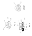
- FIG. 32 is a perspective view illustrating the procedure for setting up a receptacle part in a seventh embodiment of the present. invention.
- FIG. 33 is a perspective view illustrating the procedure for setting up a receptacle part in a eighth embodiment of the present invention.
- FIG. 10 an appearance of the receptacle part 30 and the plug part 40 in a super mini coaxial microwave connector according to the present invention is illustrated respectively and it can be seen that the receptacle part 30 and the plug part 40 are almost identical with the receptacle part 10 and the plug part 20 in the conventional connector shown in FIG. 9 .
- the difference of the connector disclosed in the present invention from the prior art is in that the connector of the present invention does not provide connecting piece extending from a connector body 31 of the receptacle part 30 but the connecting piece 111 shown in FIG. 9 does extend from the receptacle part 11 .
- the female terminal 41 of the plug part 40 (shown in FIG.
- FIG. 11 in the connector of the present invention has an upper plate 413 and a back plate 412 being bent downward.
- the back plate 412 at two opposite sides thereof has a bent contact plate 411 respectively.
- the two contact plates 411 and the back plate 412 are used for contacting with the male terminal 33 of the receptacle part 30 and FIG. 2 shows a female terminal 23 in the conventional connector contacts with the male terminal 13 of the receptacle part by way of two contact plates 231 only so that the female terminal 41 can contact with the male terminal 33 much more steadily if it compares to the female terminal 23 contacting with the male terminal 13 in the conventional connector.
- the upper plate 413 on the female terminal 41 has a concave stop neck 414 with two opposite downward bent stop plates 415 behind the stop neck 414 .
- An inner lead wire at a partial length thereof extended into the coaxial line can be fixed and soldered between the stop neck 414 and the stop plates 415 .
- the inner lead wire at another partial length thereof extended under the upper plate 413 can be fixed and soldered under the upper plate 413 steadily such that the speed for the coaxial line joining with the female terminal can be enhanced with a promoted joint steadily.
- the female terminal 41 has two contact plates 411 and the back plate thereof being in a state of being not bent downward before the receptacle part being assembled.
- a recess 416 is provided at a joint between the back plate and the upper plate 413 to facilitate the back plate being bent downward and to offer a specific position during bending the back plate.
- FIGS. 13A and 13B while the receptacle part of the present invention is assembled, the female terminal 41 with the coaxial line (not shown) in company with the insulator 42 is inserted into a hole 431 in the casing 43 along the axis of the casing 43 first and then the lead wire in the coaxial line is soldered to the stop neck 414 between two stop plates 415 .
- the FIG. 13A shows the contact plates 411 are disposed at a facial side of the upper plate 413 and the stop plates 415 are disposed at another facial side of the upper plates 413 .
- FIG. 13B shows the contact plates 411 and the stop plates 415 are disposed at another side of the upper plate 413 .
- the assembling job for the plug part of the present invention is much more convenient than the conventional plug part shown in FIG. 8 and it makes the inner lead wire being joined to the female terminal more steady.
- the female terminal 44 has a stopper 441 , which is an downward plate punched from the upper plate 442 so that an opening 443 is formed on the upper plate 442 instead of the stop neck 414 on the female terminal 41 shown in FIG. 12 .
- the receptacle part of the present invention can be fabricated by way of a blanking band 330 of male terminals 33 and a blanking band 310 of connector bodies 31 .
- Each of the male terminals 33 on the blanking band 330 is inserted into a central hollow area in each of the connector bodies 31 on the blanking band 310 as shown in FIG. 16 .
- the blanking band 330 and the blanking band 310 are placed in an injection mold such that a respective insulator 32 between each male terminal and each connector body 31 as shown in FIG. 17 can be formed by way of injected plastic material.
- each connector body to be attached to the blanking band 310 via two opposite guide pieces 311 as shown in FIG. 17 so that a much firmer contact between each connector band 31 and the blanking band 310 can be obtained and it is not possible for the connector body 31 to become deviated during the insulators 32 being form through the injection molding so as to avoid causing defectives.
- the guide pieces 311 are cut down, both lateral sides of the respective connector are subjected to an identical force respectively so that it is not possible for the respective connector part 31 to become deformed as a defective easily.
- connection plate 111 extending beyond the insulator 12 in the conventional receptacle 10 shown in FIG. 9 is not provided in the receptacle part 30 of the present embodiment so that short circuit resulting from other electronic components neighboring the receptacle part 30 will not occur and it is not possible to hurt fingers of the worker during fixing the receptacle part.
- FIG. 20 another blanking band 340 is illustrated.
- the blanking band 340 provides every two neighboring guide pieces 341 connecting with two ends of top section on each T-shaped connection plate 342 respectively and the T-shaped connection plate 342 at the lower end :thereof is attached to the blanking band 340 so that :each connector part 34 can be held firmly with the connection plate 342 .
- the receptacle part made from the blanking band 340 provides the same function as that made from the blanking band 310 shown in FIG. 17 .
- the blanking band 510 provides every two neighboring guide pieces 511 attaching with a longitudinal connection plate 512 respectively and the two connection plates 512 at another end thereof are connected to a transverse connection plate 513 .
- Each transverse connection plate 513 at both ends thereof connects with two parallel the blanking bands 510 .
- the insulators 52 made from the injection molding are disposed under the connector bodies respectively in advance.
- the connector body 51 shown in FIG. 21 is utilized to join an insulator 52 and then a male terminal 53 is inserted into the connector body 51 through the a central hole in the insulator 52 so as to form a receptacle part 50 as shown in FIG. 23 .
- the male terminal 53 of the receptacle part 50 (shown in FIG. 24) has an annular projection 531 to retain an outer rim of the central hole 521 as soon as the male terminal 53 at the upper section thereof with the annular projection 531 pierces the central hole 521 .
- the lower section of the male terminal 53 is bent at the bottom of the insulator 52 so that the male terminal 53 can engage with the insulator 52 firmly.
- the preceding male terminal 53 is fabricated by way of a lathe so that it is possible to have a better contact surface to tightly fit with the female terminal.
- the connector body 51 is seamlessly made by way of extraction or a lathe.
- a fourth embodiment of the present invention provides a receptacle part 60 and the connector part 61 is made by way of a wound plate with a seam.
- a receptacle part 70 is set up with the following steps. Two opposite guide extensions 711 at the lower edge of the connector body 71 pierce two opposite openings in the insulator 72 first. Then, the guide extensions 711 are bent over to fix the guide extensions 711 at the bottom of the insulator 72 . Finally, the male terminal 73 is inserted into the connector body 71 and the lower end of the male terminal 73 is fixed to a further locating groove 722 at the bottom of the insulator 72 .
- a male terminal blanking band 830 is provided and the male terminals 83 on the blanking band 830 are attached with insulators 82 , which are made by way of injection molding, to form an arrangement the insulators 82 being joined to the male terminals 83 .
- connector bodies 81 engage with the insulators 82 by way of identical steps illustrating in FIG. 26 so that the receptacle part 80 can be set up completely as shown in FIG. 29 .
- the male terminal 90 of the present invention can be formed by way of solid stamping or lathe work.
- An extended end 901 from the male terminal 90 can be bent over such that part of the extended end 901 can touch the bottom of the male terminal 90 as shown in FIG. 30 or can be bent over to be disposed next to the bottom of the male terminal as shown in FIG. 31 instead of contacting with the bottom of the male terminal 90 .
- a connector part 91 which is made by way of the method shown in FIG. 21, is attached with the insulator 92 to constitute a connector body. Then, the male terminal 90 is inserted into the connector body through a central hole in the insulator 92 as shown in FIG. 30 to form the receptacle part 93 .
- a connector body 91 which is made by way of the method shown in FIG. 21, is attached with the insulator 92 to constitute a connector body. Then, the male terminal 90 is inserted into the connector body through a central hole in the insulator 92 as shown in FIG. 31 to form the receptacle part 94 .
- the connector body of the receptacle part connects with the blanking band by way of guide pieces directly so that it is not necessary to design extra connecting plates and the connector body can be made with one of preceding multiple ways so that the connector of the present invention can be made with a versatile ways in accordance with the machine available to facilitate the manufacturing process and the defective rate can be reduced substantially to save the production cost.
Landscapes
- Coupling Device And Connection With Printed Circuit (AREA)
Abstract
Description
Claims (20)
Priority Applications (1)
| Application Number | Priority Date | Filing Date | Title |
|---|---|---|---|
| US10/035,313 US6648653B2 (en) | 2002-01-04 | 2002-01-04 | Super mini coaxial microwave connector |
Applications Claiming Priority (1)
| Application Number | Priority Date | Filing Date | Title |
|---|---|---|---|
| US10/035,313 US6648653B2 (en) | 2002-01-04 | 2002-01-04 | Super mini coaxial microwave connector |
Publications (2)
| Publication Number | Publication Date |
|---|---|
| US20030129858A1 US20030129858A1 (en) | 2003-07-10 |
| US6648653B2 true US6648653B2 (en) | 2003-11-18 |
Family
ID=21881883
Family Applications (1)
| Application Number | Title | Priority Date | Filing Date |
|---|---|---|---|
| US10/035,313 Expired - Fee Related US6648653B2 (en) | 2002-01-04 | 2002-01-04 | Super mini coaxial microwave connector |
Country Status (1)
| Country | Link |
|---|---|
| US (1) | US6648653B2 (en) |
Cited By (35)
| Publication number | Priority date | Publication date | Assignee | Title |
|---|---|---|---|---|
| US20040137764A1 (en) * | 2002-12-26 | 2004-07-15 | Masahiro Yamane | Coaxial electrical connector |
| US20040192107A1 (en) * | 2003-03-31 | 2004-09-30 | Kazuhiko Ikeda | Coaxial connector |
| US20050136701A1 (en) * | 2003-12-19 | 2005-06-23 | Kazuhiko Ikeda | Coaxial electrical connector |
| US20080034583A1 (en) * | 2006-08-14 | 2008-02-14 | Li-Sen Chen | Manufacturing method of radio frequency connector |
| US20080268705A1 (en) * | 2007-04-25 | 2008-10-30 | Hirose Electric Co., Ltd. | Coaxial electrical connector |
| US20090117779A1 (en) * | 2007-11-02 | 2009-05-07 | Hon Hai Precision Ind. Co., Ltd. | Coaxial electrical connector |
| US20090247008A1 (en) * | 2008-03-25 | 2009-10-01 | Hon Hai Precision Ind. Co., Ltd. | Receptacle rf connector having interferential engagement between contact terminal and housing |
| US20090305544A1 (en) * | 2006-02-17 | 2009-12-10 | Molex Incorporated | Floating Connector Holder |
| US20100190376A1 (en) * | 2007-07-09 | 2010-07-29 | Sung-Wen Chen | Receptacle of RF microwave connector for telecommunication |
| AU2007322111B2 (en) * | 2006-11-21 | 2010-09-23 | Pt Motion Works, Inc. | Self-propelled vehicle propelled by an elliptical drive train |
| US20100248503A1 (en) * | 2007-11-06 | 2010-09-30 | Kang Kyoung Il | Connector capable of coupling to printed circuit board |
| US20110136378A1 (en) * | 2009-12-07 | 2011-06-09 | Daisuke Yamakoshi | Method of installing antenna and coaxial connector |
| US20110181377A1 (en) * | 2010-01-22 | 2011-07-28 | Kenneth Vanhille | Thermal management |
| US20110181376A1 (en) * | 2010-01-22 | 2011-07-28 | Kenneth Vanhille | Waveguide structures and processes thereof |
| US20110210807A1 (en) * | 2003-03-04 | 2011-09-01 | Sherrer David W | Coaxial waveguide microstructures and methods of formation thereof |
| US8087940B1 (en) * | 2010-11-03 | 2012-01-03 | Abc Taiwan Electronics Corp. | Coaxial electric connector |
| US20120009812A1 (en) * | 2009-03-16 | 2012-01-12 | Kang Kyoung Il | Connector mounted on printed circuit board |
| US8542079B2 (en) | 2007-03-20 | 2013-09-24 | Nuvotronics, Llc | Coaxial transmission line microstructure including an enlarged coaxial structure for transitioning to an electrical connector |
| US8814601B1 (en) | 2011-06-06 | 2014-08-26 | Nuvotronics, Llc | Batch fabricated microconnectors |
| US8866300B1 (en) | 2011-06-05 | 2014-10-21 | Nuvotronics, Llc | Devices and methods for solder flow control in three-dimensional microstructures |
| US8933769B2 (en) | 2006-12-30 | 2015-01-13 | Nuvotronics, Llc | Three-dimensional microstructures having a re-entrant shape aperture and methods of formation |
| US9024417B2 (en) | 2007-03-20 | 2015-05-05 | Nuvotronics, Llc | Integrated electronic components and methods of formation thereof |
| US9306255B1 (en) | 2013-03-15 | 2016-04-05 | Nuvotronics, Inc. | Microstructure including microstructural waveguide elements and/or IC chips that are mechanically interconnected to each other |
| US9306254B1 (en) | 2013-03-15 | 2016-04-05 | Nuvotronics, Inc. | Substrate-free mechanical interconnection of electronic sub-systems using a spring configuration |
| US9325044B2 (en) | 2013-01-26 | 2016-04-26 | Nuvotronics, Inc. | Multi-layer digital elliptic filter and method |
| US9993982B2 (en) | 2011-07-13 | 2018-06-12 | Nuvotronics, Inc. | Methods of fabricating electronic and mechanical structures |
| US10310009B2 (en) | 2014-01-17 | 2019-06-04 | Nuvotronics, Inc | Wafer scale test interface unit and contactors |
| US10319654B1 (en) | 2017-12-01 | 2019-06-11 | Cubic Corporation | Integrated chip scale packages |
| US10497511B2 (en) | 2009-11-23 | 2019-12-03 | Cubic Corporation | Multilayer build processes and devices thereof |
| US10511073B2 (en) | 2014-12-03 | 2019-12-17 | Cubic Corporation | Systems and methods for manufacturing stacked circuits and transmission lines |
| US10840642B2 (en) * | 2017-12-18 | 2020-11-17 | Tyco Electronics Amp Korea Co. Ltd. | Connector assembly and method of manufacturing socket for connector assembly |
| US10847469B2 (en) | 2016-04-26 | 2020-11-24 | Cubic Corporation | CTE compensation for wafer-level and chip-scale packages and assemblies |
| US10923830B2 (en) * | 2019-01-18 | 2021-02-16 | Pc-Tel, Inc. | Quick solder chip connector for massive multiple-input multiple-output antenna systems |
| US11411341B2 (en) * | 2019-10-17 | 2022-08-09 | Foxconn (Kunshan) Computer Connector Co., Ltd. | Metallic outer shell of an electrical connector having curvilinear flaps and interposed springy flaps |
| US11411340B2 (en) * | 2019-10-17 | 2022-08-09 | Foxconn (Kunshan) Computer Connector Co., Ltd. | Seamless metallic outer shell of an electrical connector having inward bulges |
Families Citing this family (6)
| Publication number | Priority date | Publication date | Assignee | Title |
|---|---|---|---|---|
| JP2006066384A (en) * | 2004-07-27 | 2006-03-09 | Hosiden Corp | Coaxial connector for board-to-board connection |
| EP1989760A1 (en) * | 2006-02-28 | 2008-11-12 | Huber+Suhner AG | Bent-back plug-type connector for coaxial cables |
| JP5131455B2 (en) * | 2007-12-05 | 2013-01-30 | 第一精工株式会社 | Coaxial connector device |
| TWM347726U (en) * | 2008-02-01 | 2008-12-21 | Yang-Yin Li | Connector |
| CN202759104U (en) * | 2012-07-18 | 2013-02-27 | 番禺得意精密电子工业有限公司 | Electric connector |
| JP7344150B2 (en) * | 2020-02-10 | 2023-09-13 | ヒロセ電機株式会社 | How to make coaxial electrical connectors |
Citations (4)
| Publication number | Priority date | Publication date | Assignee | Title |
|---|---|---|---|---|
| US3771111A (en) * | 1972-06-12 | 1973-11-06 | Amp Inc | Flag type electrical terminal |
| US5772470A (en) * | 1996-06-03 | 1998-06-30 | Smk Corporation | Coaxial connector |
| US6474995B1 (en) * | 2001-10-30 | 2002-11-05 | Hon Hai Precision Ind. Co., Ltd. | Low profile RF connector and method of manufacturing the RF connector |
| US6503100B2 (en) * | 1999-07-30 | 2003-01-07 | Hirose Electric Co., Ltd. | Connector terminal and L-shaped connector using the same |
-
2002
- 2002-01-04 US US10/035,313 patent/US6648653B2/en not_active Expired - Fee Related
Patent Citations (5)
| Publication number | Priority date | Publication date | Assignee | Title |
|---|---|---|---|---|
| US3771111A (en) * | 1972-06-12 | 1973-11-06 | Amp Inc | Flag type electrical terminal |
| US5772470A (en) * | 1996-06-03 | 1998-06-30 | Smk Corporation | Coaxial connector |
| US6503100B2 (en) * | 1999-07-30 | 2003-01-07 | Hirose Electric Co., Ltd. | Connector terminal and L-shaped connector using the same |
| US6508668B1 (en) * | 1999-07-30 | 2003-01-21 | Hirose Electric Co., Ltd. | L-shaped coaxial connector and terminal for the same |
| US6474995B1 (en) * | 2001-10-30 | 2002-11-05 | Hon Hai Precision Ind. Co., Ltd. | Low profile RF connector and method of manufacturing the RF connector |
Cited By (62)
| Publication number | Priority date | Publication date | Assignee | Title |
|---|---|---|---|---|
| US6902408B2 (en) * | 2002-12-26 | 2005-06-07 | Hirose Electric Co., Ltd. | Coaxial electrical connector |
| US20040137764A1 (en) * | 2002-12-26 | 2004-07-15 | Masahiro Yamane | Coaxial electrical connector |
| US8742874B2 (en) | 2003-03-04 | 2014-06-03 | Nuvotronics, Llc | Coaxial waveguide microstructures having an active device and methods of formation thereof |
| US9312589B2 (en) | 2003-03-04 | 2016-04-12 | Nuvotronics, Inc. | Coaxial waveguide microstructure having center and outer conductors configured in a rectangular cross-section |
| US10074885B2 (en) | 2003-03-04 | 2018-09-11 | Nuvotronics, Inc | Coaxial waveguide microstructures having conductors formed by plural conductive layers |
| US20110210807A1 (en) * | 2003-03-04 | 2011-09-01 | Sherrer David W | Coaxial waveguide microstructures and methods of formation thereof |
| US20040192107A1 (en) * | 2003-03-31 | 2004-09-30 | Kazuhiko Ikeda | Coaxial connector |
| US20050136701A1 (en) * | 2003-12-19 | 2005-06-23 | Kazuhiko Ikeda | Coaxial electrical connector |
| US6997745B2 (en) * | 2003-12-19 | 2006-02-14 | Hirose Electric Co., Ltd. | Coaxial electrical connector |
| US20090305544A1 (en) * | 2006-02-17 | 2009-12-10 | Molex Incorporated | Floating Connector Holder |
| US7980859B2 (en) * | 2006-02-17 | 2011-07-19 | Molex Incorporated | Floating connector holder |
| US7334327B1 (en) * | 2006-08-14 | 2008-02-26 | Speed Tech Corp. | Manufacturing method of radio frequency connector |
| US20080034583A1 (en) * | 2006-08-14 | 2008-02-14 | Li-Sen Chen | Manufacturing method of radio frequency connector |
| AU2007322111B2 (en) * | 2006-11-21 | 2010-09-23 | Pt Motion Works, Inc. | Self-propelled vehicle propelled by an elliptical drive train |
| US8933769B2 (en) | 2006-12-30 | 2015-01-13 | Nuvotronics, Llc | Three-dimensional microstructures having a re-entrant shape aperture and methods of formation |
| US9515364B1 (en) | 2006-12-30 | 2016-12-06 | Nuvotronics, Inc. | Three-dimensional microstructure having a first dielectric element and a second multi-layer metal element configured to define a non-solid volume |
| US9000863B2 (en) | 2007-03-20 | 2015-04-07 | Nuvotronics, Llc. | Coaxial transmission line microstructure with a portion of increased transverse dimension and method of formation thereof |
| US10431521B2 (en) | 2007-03-20 | 2019-10-01 | Cubic Corporation | Integrated electronic components and methods of formation thereof |
| US9024417B2 (en) | 2007-03-20 | 2015-05-05 | Nuvotronics, Llc | Integrated electronic components and methods of formation thereof |
| US10002818B2 (en) | 2007-03-20 | 2018-06-19 | Nuvotronics, Inc. | Integrated electronic components and methods of formation thereof |
| US9570789B2 (en) | 2007-03-20 | 2017-02-14 | Nuvotronics, Inc | Transition structure between a rectangular coaxial microstructure and a cylindrical coaxial cable using step changes in center conductors thereof |
| US8542079B2 (en) | 2007-03-20 | 2013-09-24 | Nuvotronics, Llc | Coaxial transmission line microstructure including an enlarged coaxial structure for transitioning to an electrical connector |
| US20080268705A1 (en) * | 2007-04-25 | 2008-10-30 | Hirose Electric Co., Ltd. | Coaxial electrical connector |
| US7445458B1 (en) * | 2007-04-25 | 2008-11-04 | Hirose Electric Co., Ltd. | Coaxial electrical connector |
| US20100190376A1 (en) * | 2007-07-09 | 2010-07-29 | Sung-Wen Chen | Receptacle of RF microwave connector for telecommunication |
| US7651334B2 (en) * | 2007-11-02 | 2010-01-26 | Hon Hai Precision Ind. Co., Ltd. | Coaxial electrical connector |
| US20090117779A1 (en) * | 2007-11-02 | 2009-05-07 | Hon Hai Precision Ind. Co., Ltd. | Coaxial electrical connector |
| US20100248503A1 (en) * | 2007-11-06 | 2010-09-30 | Kang Kyoung Il | Connector capable of coupling to printed circuit board |
| US20090247008A1 (en) * | 2008-03-25 | 2009-10-01 | Hon Hai Precision Ind. Co., Ltd. | Receptacle rf connector having interferential engagement between contact terminal and housing |
| US7651335B2 (en) * | 2008-03-25 | 2010-01-26 | Hon Hai Precision Ind. Co., Ltd. | Receptacle RF connector having interferential engagement between contact terminal and housing |
| US8333596B2 (en) * | 2009-03-16 | 2012-12-18 | Gigalane Co., Ltd. | Connector having a tail with vertical panels inserted into a dielectric holding a contact terminal surrounded by a body |
| US20120009812A1 (en) * | 2009-03-16 | 2012-01-12 | Kang Kyoung Il | Connector mounted on printed circuit board |
| US10497511B2 (en) | 2009-11-23 | 2019-12-03 | Cubic Corporation | Multilayer build processes and devices thereof |
| US8414328B2 (en) * | 2009-12-07 | 2013-04-09 | Hirose Electric Co., Ltd. | Method of installing antenna and coaxial connector |
| US20110136378A1 (en) * | 2009-12-07 | 2011-06-09 | Daisuke Yamakoshi | Method of installing antenna and coaxial connector |
| US8717124B2 (en) | 2010-01-22 | 2014-05-06 | Nuvotronics, Llc | Thermal management |
| US8917150B2 (en) | 2010-01-22 | 2014-12-23 | Nuvotronics, Llc | Waveguide balun having waveguide structures disposed over a ground plane and having probes located in channels |
| US20110181376A1 (en) * | 2010-01-22 | 2011-07-28 | Kenneth Vanhille | Waveguide structures and processes thereof |
| US20110181377A1 (en) * | 2010-01-22 | 2011-07-28 | Kenneth Vanhille | Thermal management |
| US8087940B1 (en) * | 2010-11-03 | 2012-01-03 | Abc Taiwan Electronics Corp. | Coaxial electric connector |
| US8866300B1 (en) | 2011-06-05 | 2014-10-21 | Nuvotronics, Llc | Devices and methods for solder flow control in three-dimensional microstructures |
| US9505613B2 (en) | 2011-06-05 | 2016-11-29 | Nuvotronics, Inc. | Devices and methods for solder flow control in three-dimensional microstructures |
| US9583856B2 (en) | 2011-06-06 | 2017-02-28 | Nuvotronics, Inc. | Batch fabricated microconnectors |
| US8814601B1 (en) | 2011-06-06 | 2014-08-26 | Nuvotronics, Llc | Batch fabricated microconnectors |
| US9993982B2 (en) | 2011-07-13 | 2018-06-12 | Nuvotronics, Inc. | Methods of fabricating electronic and mechanical structures |
| US9608303B2 (en) | 2013-01-26 | 2017-03-28 | Nuvotronics, Inc. | Multi-layer digital elliptic filter and method |
| US9325044B2 (en) | 2013-01-26 | 2016-04-26 | Nuvotronics, Inc. | Multi-layer digital elliptic filter and method |
| US9306254B1 (en) | 2013-03-15 | 2016-04-05 | Nuvotronics, Inc. | Substrate-free mechanical interconnection of electronic sub-systems using a spring configuration |
| US10193203B2 (en) | 2013-03-15 | 2019-01-29 | Nuvotronics, Inc | Structures and methods for interconnects and associated alignment and assembly mechanisms for and between chips, components, and 3D systems |
| US10257951B2 (en) | 2013-03-15 | 2019-04-09 | Nuvotronics, Inc | Substrate-free interconnected electronic mechanical structural systems |
| US10361471B2 (en) | 2013-03-15 | 2019-07-23 | Nuvotronics, Inc | Structures and methods for interconnects and associated alignment and assembly mechanisms for and between chips, components, and 3D systems |
| US9306255B1 (en) | 2013-03-15 | 2016-04-05 | Nuvotronics, Inc. | Microstructure including microstructural waveguide elements and/or IC chips that are mechanically interconnected to each other |
| US9888600B2 (en) | 2013-03-15 | 2018-02-06 | Nuvotronics, Inc | Substrate-free interconnected electronic mechanical structural systems |
| US10310009B2 (en) | 2014-01-17 | 2019-06-04 | Nuvotronics, Inc | Wafer scale test interface unit and contactors |
| US10511073B2 (en) | 2014-12-03 | 2019-12-17 | Cubic Corporation | Systems and methods for manufacturing stacked circuits and transmission lines |
| US10847469B2 (en) | 2016-04-26 | 2020-11-24 | Cubic Corporation | CTE compensation for wafer-level and chip-scale packages and assemblies |
| US10319654B1 (en) | 2017-12-01 | 2019-06-11 | Cubic Corporation | Integrated chip scale packages |
| US10553511B2 (en) | 2017-12-01 | 2020-02-04 | Cubic Corporation | Integrated chip scale packages |
| US10840642B2 (en) * | 2017-12-18 | 2020-11-17 | Tyco Electronics Amp Korea Co. Ltd. | Connector assembly and method of manufacturing socket for connector assembly |
| US10923830B2 (en) * | 2019-01-18 | 2021-02-16 | Pc-Tel, Inc. | Quick solder chip connector for massive multiple-input multiple-output antenna systems |
| US11411341B2 (en) * | 2019-10-17 | 2022-08-09 | Foxconn (Kunshan) Computer Connector Co., Ltd. | Metallic outer shell of an electrical connector having curvilinear flaps and interposed springy flaps |
| US11411340B2 (en) * | 2019-10-17 | 2022-08-09 | Foxconn (Kunshan) Computer Connector Co., Ltd. | Seamless metallic outer shell of an electrical connector having inward bulges |
Also Published As
| Publication number | Publication date |
|---|---|
| US20030129858A1 (en) | 2003-07-10 |
Similar Documents
| Publication | Publication Date | Title |
|---|---|---|
| US6648653B2 (en) | Super mini coaxial microwave connector | |
| US5060373A (en) | Methods for making coaxial connectors | |
| US6902408B2 (en) | Coaxial electrical connector | |
| US9478916B2 (en) | Electrical plug connector | |
| US6572407B1 (en) | Low profile cable end connector | |
| US20170070015A1 (en) | Electrical plug connector | |
| JP2000243490A (en) | Coaxial coupling to interconnect two printed circuit cards | |
| CN111883960B (en) | Radio frequency switch | |
| CN106816786B (en) | Radio frequency connector assembly | |
| KR20050026912A (en) | Connector | |
| CN1250031C (en) | Coaxial connecting element and communication apparatus with the same coaxial connecting element | |
| JP2022176124A (en) | Crimp contact, crimp connection, and method for forming crimp connection | |
| US6428355B1 (en) | Coaxial cable assembly | |
| CN111697402B (en) | Coaxial Connectors | |
| US20060094297A1 (en) | Terminal structure of a coaxial connector | |
| CN112310580B (en) | RF Switch | |
| US20060128172A1 (en) | Coaxial connector | |
| US12388209B2 (en) | Terminal, molding method and electrical connector | |
| JP3235510U (en) | Piercing electric connector and jig for joining electric connector and cable | |
| CN214589321U (en) | Type-C electric connector | |
| CN112531441B (en) | Preparation process of wire-to-board connector terminal | |
| KR100276583B1 (en) | Electrical connection terminal manufacturing method | |
| CN210897712U (en) | Terminal and electric connector with same | |
| US6241564B1 (en) | Carrier plate for forming a plug contact | |
| CN112310579B (en) | RF switches |
Legal Events
| Date | Code | Title | Description |
|---|---|---|---|
| AS | Assignment |
Owner name: INSERT ENTERPRISE CO., LTD., TAIWAN Free format text: ASSIGNMENT OF ASSIGNORS INTEREST;ASSIGNORS:HUANG, TUNG-LIANG;CHEN, SUNG-WEN;REEL/FRAME:012433/0526 Effective date: 20011214 |
|
| FPAY | Fee payment |
Year of fee payment: 4 |
|
| SULP | Surcharge for late payment | ||
| FPAY | Fee payment |
Year of fee payment: 8 |
|
| REMI | Maintenance fee reminder mailed | ||
| LAPS | Lapse for failure to pay maintenance fees | ||
| STCH | Information on status: patent discontinuation |
Free format text: PATENT EXPIRED DUE TO NONPAYMENT OF MAINTENANCE FEES UNDER 37 CFR 1.362 |
|
| STCH | Information on status: patent discontinuation |
Free format text: PATENT EXPIRED DUE TO NONPAYMENT OF MAINTENANCE FEES UNDER 37 CFR 1.362 |
|
| FP | Lapsed due to failure to pay maintenance fee |
Effective date: 20151118 |