US6640004B2 - Image sensing and image processing apparatuses - Google Patents
Image sensing and image processing apparatuses Download PDFInfo
- Publication number
- US6640004B2 US6640004B2 US08/686,683 US68668396A US6640004B2 US 6640004 B2 US6640004 B2 US 6640004B2 US 68668396 A US68668396 A US 68668396A US 6640004 B2 US6640004 B2 US 6640004B2
- Authority
- US
- United States
- Prior art keywords
- image
- image sensing
- images
- subject
- information
- Prior art date
- Legal status (The legal status is an assumption and is not a legal conclusion. Google has not performed a legal analysis and makes no representation as to the accuracy of the status listed.)
- Expired - Fee Related
Links
Images


Classifications
-
- G—PHYSICS
- G06—COMPUTING; CALCULATING OR COUNTING
- G06T—IMAGE DATA PROCESSING OR GENERATION, IN GENERAL
- G06T15/00—3D [Three Dimensional] image rendering
- G06T15/10—Geometric effects
-
- G—PHYSICS
- G06—COMPUTING; CALCULATING OR COUNTING
- G06T—IMAGE DATA PROCESSING OR GENERATION, IN GENERAL
- G06T17/00—Three dimensional [3D] modelling, e.g. data description of 3D objects
- G06T17/10—Constructive solid geometry [CSG] using solid primitives, e.g. cylinders, cubes
-
- G—PHYSICS
- G06—COMPUTING; CALCULATING OR COUNTING
- G06T—IMAGE DATA PROCESSING OR GENERATION, IN GENERAL
- G06T7/00—Image analysis
- G06T7/50—Depth or shape recovery
- G06T7/55—Depth or shape recovery from multiple images
- G06T7/593—Depth or shape recovery from multiple images from stereo images
-
- G—PHYSICS
- G06—COMPUTING; CALCULATING OR COUNTING
- G06T—IMAGE DATA PROCESSING OR GENERATION, IN GENERAL
- G06T7/00—Image analysis
- G06T7/70—Determining position or orientation of objects or cameras
-
- G—PHYSICS
- G06—COMPUTING; CALCULATING OR COUNTING
- G06T—IMAGE DATA PROCESSING OR GENERATION, IN GENERAL
- G06T7/00—Image analysis
- G06T7/80—Analysis of captured images to determine intrinsic or extrinsic camera parameters, i.e. camera calibration
-
- G—PHYSICS
- G06—COMPUTING; CALCULATING OR COUNTING
- G06V—IMAGE OR VIDEO RECOGNITION OR UNDERSTANDING
- G06V10/00—Arrangements for image or video recognition or understanding
- G06V10/10—Image acquisition
- G06V10/12—Details of acquisition arrangements; Constructional details thereof
- G06V10/14—Optical characteristics of the device performing the acquisition or on the illumination arrangements
- G06V10/147—Details of sensors, e.g. sensor lenses
-
- G—PHYSICS
- G06—COMPUTING; CALCULATING OR COUNTING
- G06T—IMAGE DATA PROCESSING OR GENERATION, IN GENERAL
- G06T2200/00—Indexing scheme for image data processing or generation, in general
- G06T2200/08—Indexing scheme for image data processing or generation, in general involving all processing steps from image acquisition to 3D model generation
Definitions
- the present invention relates to an image sensing apparatus capable of determining optimum image sensing conditions for obtaining a three-dimensional image.
- the present invention also relates to an image processing apparatus which edits a three-dimensional image in accordance with the image sensing conditions.
- a typical method as the passive method is a stereo imaging method which performs triangulation on an object by using two cameras.
- corresponding points of a part of an object are searched in both the right and left images, and the position of the object in the three dimensional space is measured on the basis of the difference between the positions of the searched corresponding points in the right and left images.
- a method using a range finder and a slit projection method as the typical active method.
- distance to the object is obtained by measuring the elapsed time between emitting light toward the object and receiving the light reflected by the object.
- a three-dimensional shape is measured on the basis of deformation of a shape of a light pattern, whose original pattern is a slit shape, projected on an object.
- the main purpose of the aforesaid stereo imaging method is to calculate information on distance between fixed positions where the cameras are set and the object, and not to measure the entire object. Consequently, a three-dimensional shape can not be obtained in high precision.
- an apparatus adopting the active method is large, since it has to emit a laser beam, for example, to an object the manufacturing cost is, therefore, high.
- cameras are not controlled flexibly enough to respond to a dynamic image sensing method, such as sensing an object while moving around it.
- the present invention is aimed at solving the aforesaid problem, i.e., to realize a dynamic image sensing method in which an object is sensed at a plurality of image sensing points around it.
- a scene is divided into a plurality of partial scenes, and then is sensed with an electronic camera.
- the images corresponding to the plurality of partial scenes is projected with having some overlapping portions.
- the sensed images are inputted into a personal computer, then put together by using an application software so that the overlapping portions are projected overlapping each other. Thereby, it is possible to obtain an image of far wider angle of view than that of an image obtained in a single image sensing operation by the electronic camera.
- the main purpose of the aforesaid stereo imaging method is to calculate information on distance between a fixed position where the camera is set and the object, and not to measure the three-dimensional shape of the entire object.
- two view finders are necessary in the conventional passive method using two cameras, and it is also necessary to perform image sensing operation as seeing to compare images on the two view finders, which increases manufacturing cost and provides bad operability. For instance, there are problems in which it takes time to perform framing or it becomes impossible to obtain a three-dimensional shape because of too small of an overlapping area.
- an image generally dealt with in an office is often printed out on paper eventually, and types of images to be used may be a natural image and a wire image which represents an object with outlines only.
- display an image of an object faithfully on a two-dimensional display on the basis of three-dimensional shape data of the object is the main interest, thus those methods are not used in offices.
- the present invention has been made in consideration of the aforesaid situation, and has as its object to provide an image sensing apparatus capable of placing an object, whose three-dimensional shape is to be generated, under the optimum image sensing conditions upon sensing the object from a plurality of image sensing points without bothering an operator.
- a further object of the present invention is to provide an image sensing apparatus which senses an image of the object with the optimum zoom ratio at each of a plurality of image sensing points.
- Yet a further object of the present invention is to provide an image sensing apparatus capable of notifying an operator of achievement of the optimum image sensing conditions.
- Yet further object of the present invention is to provide an image sensing apparatus capable of storing the optimum image sensing conditions.
- Yet a further object of the present invention is to provide an image sensing apparatus which determines whether the optimum image sensing conditions are achieved or not by judging whether there is a predetermined pattern in an image sensing field.
- Yet a further object of the present invention is to provide an image sensing apparatus capable of re-sensing an image.
- Yet a further object of the present invention is to provide an image sensing apparatus whose operability is greatly improved by informing an operator when he/she is to press a shutter.
- Yet a further object of the present invention is to provide an image sensing apparatus capable of determining a displacing speed of a camera upon inputting an image, thereby improving operability as well as quality of an input image.
- Yet a further object of the present invention is to provide a single-eye type image sensing apparatus capable of inputting an image of high quality thereby obtaining a three-dimensional shape in high precision and reliability.
- Yet a further object of the present invention is to provide an image sensing apparatus capable of always sensing characteristic points to be used for posture detection within a field of view, thereby preventing failing an image sensing operation.
- Yet a further object of the present invention is to provide an image processing apparatus capable of generating an image of an object which is seen from an arbitrary viewpoint on the basis of three-dimensional shape information on images sensed at a plurality of image sensing points, and capable of forming a file.
- Yet a further object of the present invention is to provide an image processing apparatus capable of generating an image of an object which is seen from an arbitrary viewpoint on the basis of three-dimensional shape information on images sensed at a plurality of image sensing points, and capable of forming a file, and further editing the three-dimensional image by synthesizing the file with other file.
- Yet a further object of the present invention is to provide an image processing apparatus which generates a three-dimensional image from images sensed under the optimum image sensing conditions.
- Yet a further object of the present invention is to provide an image processing apparatus which converts three-dimensional shape data, obtained based on sensed images, into a two-dimensional image of an object which is seen from an arbitrary viewpoint.
- Yet a further object of the present invention is to provide an image processing apparatus which combines a document file and a three-dimensional image.
- Yet a further object of the present invention is to provide an image processing apparatus which stores information on background of an object.
- Yet a further object of the present invention is to provide an image processing apparatus which combines an image data file with another file, and has a three-dimensionally displaying function.
- Yet a further object of the present invention is to provide an image processing apparatus in which three-dimensional shape data of an object is calculated with a software installed in a computer, the three-dimensional shape data of the object is converted into an image of the object seen from an arbitrary viewpoint, and a file of the image data is combined with another file.
- Yet a further object of the present invention is to provide an image sensing apparatus capable of detecting overlapping areas in a plurality of images sensed at a plurality of image sensing points.
- Yet a further object of the present invention is to provide an image sensing apparatus which displays overlapping portions of images sensed at a plurality of image sensing points in a style different from a style for displaying non-overlapping portions.
- Yet a further object of the present invention is to provide an image processing apparatus capable of re-sensing an image.
- FIG. 1 is an explanatory view for explaining modes set in the image processing apparatuses according to first and second embodiments;
- FIG. 2 is an overall view illustrating a configuration of a three-dimensional shape recognition apparatus according to a first embodiment of the present invention
- FIG. 3 is a block diagram illustrating a configuration of a three dimensional shape information extracting apparatus according to the first embodiment
- FIG. 4 is a block diagram illustrating a configuration of a system controller shown in FIG. 3;
- FIGS. 5A, 5 B are a flowchart showing an operation according to the first embodiment
- FIG. 6 is an explanatory view for explaining in-focus point adjustment
- FIGS. 7A to 7 D are explanatory views showing zoom ratio adjustment
- FIG. 8 is a graph for explaining the zoom ratio adjustment
- FIG. 9 is an overall view illustrating a brief configuration of a three-dimensional shape recognition apparatus according to a first modification of the first embodiment
- FIG. 10 is a block diagram illustrating a configuration of a three dimensional shape information extracting apparatus according to the first modification
- FIG. 11 is a flowchart showing an operation according to the first modification
- FIG. 12 is an explanatory view showing a principle of detecting a posture according to the first modification
- FIG. 13 is a block diagram illustrating a configuration of a three dimensional shape information extracting apparatus of a second modification of the first embodiment
- FIG. 14 is a flowchart showing an operation according to the second modification
- FIG. 15 is a brief view of a three-dimensional shape extraction apparatus and its peripheral equipment according to the second embodiment
- FIG. 16 shows types of images of an object according to the second embodiment
- FIGS. 17A, 17 B are a block diagram illustrating a detailed configuration of an image sensing head and an image processing unit
- FIG. 18 is a block diagram illustrating a configuration of a system controller
- FIG. 19 shows images of an object seen from variety of viewpoints
- FIG. 20 is a diagram showing a flow of control by the apparatus according to the second embodiment.
- FIG. 21 is an explanatory view for explaining a principle of detecting an overlapping portion according to the second embodiment
- FIG. 22 is an example of an image displayed on a finder according to the second embodiment
- FIG. 23 is an table showing a form of recording three-dimensional images on a recorder according to the second embodiment
- FIG. 24 shows an operation in a panoramic image sensing according to the second embodiment
- FIG. 25 shows an operation in a panoramic image sensing according to the second embodiment
- FIG. 26 shows a brief flow for calculating distance information from stereo images according to the second embodiment
- FIG. 27 is an explanatory view for explaining a principle of a template matching according to the second embodiment
- FIG. 28 shows a brief flow for combining the distance information according to the second embodiment
- FIG. 29 is an explanatory view for briefly explaining an interpolation method according to the second embodiment.
- FIGS. 30A and 30B are explanatory view for showing a method of mapping the distance information to integrated coordinate systems according to the second embodiment
- FIG. 31 shows a brief coordinate system of an image sensing system according to the second embodiment
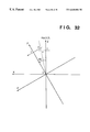
- FIG. 32 shows a brief coordinate system when the image sensing system is rotated according to the second embodiment
- FIG. 33 shows a brief flow of combining a document file, image information and the distance information according to the second embodiment
- FIG. 34 is an explanatory view showing a flow that image information is fitted to a model image according to the second embodiment
- FIG. 35 is an explanatory view showing that an image information file is combined with the document file according to the second embodiment
- FIG. 36 is a brief overall view of an image processing system according to a first modification of the second embodiment
- FIG. 37 is a block diagram illustrating a configuration of a three-dimensional shape extraction apparatus 2100 according to the first modification of the second embodiment
- FIG. 38 is a flowchart showing a processing by the three-dimensional shape extraction apparatus according to the first modification of the second embodiment
- FIG. 39 is a block diagram illustrating a configuration of a three-dimensional shape extraction apparatus according to the second modification of the second embodiment
- FIG. 40 is a flowchart showing a processing by the three-dimensional shape extraction apparatus according to the second modification of the second embodiment.
- FIG. 41 is an example of an image seen on a finder according to a third modification of the second embodiment.
- the present invention discloses an image processing apparatus which obtains images of an object sensed at a plurality of image sensing points, generates a three-dimensional image from these images and displays it.
- An image processing apparatus described in a first embodiment is characterized by three-dimensional shape recognition, especially wherein the optimum image sensing parameters are decided upon to sense the images of the object.
- an image processing apparatus described in a second embodiment it is characterized by correcting a three-dimensional image on the basis of predetermined image sensing parameters or editing a three-dimensional image.
- FIG. 1 is an explanatory view for explaining modes set in the image processing apparatuses according to the first and second embodiments.
- an image sensing parameter determination mode the optimum image sensing parameters are determined.
- a three-dimensional shape information extraction mode three-dimensional shape information of an object is extracted from images of the object sensed at a plurality of image sensing points by using image sensing parameters determined in the image sensing parameter determination mode.
- a display and editing mode a three-dimensional image is configured from three-dimensional shape information, displayed and further edited.
- a panoramic image is generated by synthesizing images sensed at a plurality of image sensing points by using a function, originally performed for extracting three-dimensional shape information, for sensing a plurality of images from a plurality of image sensing points. Further, a three-dimensional image input mode is furnished.
- FIG. 2 is an overall view illustrating a configuration of a three-dimensional shape recognition apparatus according to a first embodiment of the present invention. It is necessary to decide the most suitable image sensing parameters for recognizing three-dimensional shape information from images. The most suitable image sensing parameters make it easy to recognize, in high precision, three-dimensional shape information of an object.
- the three-dimensional shape recognition apparatus shown in FIG. 2 adopts a method of determining image sensing parameters of the present invention in order to realize reliable three-dimensional shape recognition in high precision. More specifically, in the apparatus shown in FIG. 2, after the most suitable image sensing parameters are determined, an optical system is set in accordance with the image sensing parameters, then the apparatus senses images of the object and recognizes three-dimensional shape information of the object of interest.
- reference numeral 1 denotes an apparatus (called “three-dimensional shape information extracting apparatus”, hereinafter) for extracting three-dimensional shape information of an object; and 2 , an object whose three-dimensional shape information is to be extracted, and the object 2 becomes a subject of a camera for obtaining the three-dimensional shape information of the object by an image processing in the present invention.
- reference numeral 3 denotes a stage set behind the object 2 , and it constitutes a background of the object 2 .
- reference numeral 100 R denotes a right object lens; and 100 L, a left object lens.
- reference numeral 200 denotes an illumination unit for illuminating the object 2 in accordance with an image sensing environment.
- the image sensing field of the right object lens 100 R is denoted by reference numeral 10 R
- the image sensing field of the left object lens 100 L is denoted by reference numeral 10 L.
- the three dimensional shape information extracting apparatus 1 is mounted on a vibration-type gyro (not shown), for example, and the position of the three dimensional shape information extracting apparatus 1 is detected by a posture detector 201 (refer to FIG. 3) which is also mounted on the vibration-type gyro.
- the three dimensional shape information extracting apparatus 1 senses the object 2 while moving from the start position A 0 of the image sensing to the end position A n of the image sensing. Further, position information and posture information of the three dimensional shape information extracting apparatus 1 at each image sensing point between A 0 -A n are calculated from signals obtained from the posture detector 201 of FIG. 3 .
- FIG. 3 is a block diagram illustrating a configuration of the three dimensional shape information extracting apparatus (referred to as “parameter extracting apparatus” hereinafter) 1 .
- reference numerals 100 R and 100 L denote the object lenses consisting of zoom lenses. Further, reference numerals 101 R and 101 L denote iris diaphragms; and 102 R and 102 L, image sensors and CCDs can be used as those.
- A/D converters 103 R and 103 L convert signals from the image sensors into digital signals.
- Image signal processors 104 R and 104 L convert the digital signals from the A/D converters 103 R and 103 L into image signals of a predetermined format (e.g., image signals in the YIQ system or image signals in the Lab system).
- Image separators 105 R and 105 L separate an image of the object 2 from an image of the background 3 .
- Zoom controllers 106 R and 106 L adjust focal lengths of the object (zoom) lenses 100 R and 100 L.
- Focus controllers 107 R and 107 L adjust focal points.
- Iris diaphragm controllers 108 R and 108 L adjust aperture diaphragm of the iris diaphragms 101 R and 101 L.
- Reference numeral 201 denotes the posture detector which consists of a vibration-type gyro and so on, and it outputs signals indicating the position and posture of the camera.
- Reference numeral 210 denotes a system controller which controls the overall parameter extracting apparatus 1 .
- the system controller 210 consists of a microcomputer 900 , memory 910 and an image processing section 920 .
- Reference numeral 220 denotes an image processor which extracts three-dimensional information of the object on the basis of the image signals obtained from the image sensors 102 R and 102 L, as well as outputs data after combining the three-dimensional information extracted at each image sensing point and posture information at each image sensing point obtained by the posture detector 201 .
- Reference numeral 250 denotes a recorder for recording an image.
- a focusing state detector 270 detects a focusing state of the sensed image on the basis of the image of the object 2 and the image of the background 3 separated by the image separators 105 R and 105 L.
- An R ⁇ L difference discriminator 260 calculates the differences between the obtained right image sensing parameters and left image sensing parameters.
- reference numeral 230 denotes a shutter; 280 , an external interface for external input; and 240 , a display, such as a LED.
- Images of the object 2 are inputted to the image sensors 102 R and 102 L through the object lenses 100 R and 100 L, and converted into electrical image signals.
- the obtained electrical image signals are converted from analog signals to digital signals by the A/D converters 103 R and 103 L and supplied to the image signal processors 104 R and 104 L.
- the image signal processors 104 R and 104 L convert the digitized image signals of the object into luminance signals and color signals (image signals in the YIQ system or image signals in the Lab system as described above) of a proper format.
- the image separators 105 R and 105 L separates the image of the object whose three-dimensional shape information is the subject to measurement from the image of the background 3 in the sensed image signals on the basis of the signals obtained from the image signal processors 104 R and 104 L.
- a separation method first, sense an image of the background in advance and store the sensed image in the memory (FIG. 4 ). Then, place the object 2 to be measured in front of the background 3 and sense an image of the object 2 . Thereafter, perform matching process and a differentiation process on the sensed image including the object 2 and the background 3 and the image of the background 3 which has been stored in the memory in advance, thereby separating the areas of the background 3 .
- the separation method is not limited to the above, and it is possible to separate images on the basis of information on colors or texture in the image.
- the separated image signals of the object 2 are inputted to the image processor 220 , where three-dimensional shape extraction is performed on the basis of the image sensing parameters at the image sensing operation.
- steps S 1 to step S 9 relate to the “image sensing parameter determination mode”.
- the “image sensing parameter determination mode” the optimum image sensing parameters for each of n image sensing points, or A 0 to A n shown in FIG. 2 are determined.
- each unit shown in FIG. 3 starts operating.
- the system controller 210 starts controlling at step S 1 . More specifically, the system controller 210 enables the iris diaphragm controllers 108 R and 108 L and the image sensors 102 R and 102 L so as to make them output image signals sensed through the lenses 100 R and 100 L, enables the A/D converters 103 R and 103 L so as to make them convert the image signals into digital image signals, and controls the image signal processors 104 R and 104 L to make them convert the digital image signals into image signals of the aforesaid predetermined format (includes luminance component, at least).
- the system controller 210 adjusts exposure at step S 2 .
- the system controller 210 controls the image processing section 920 (refer to FIG. 4) to perform an integral processing on the image signals of the object 2 obtained from the image separators 105 R and 105 L, and calculates a luminance level of the image of the entire object 2 . Further, the system controller 210 controls the iris diaphragm controllers 108 R and 108 L to set the iris diaphragms 101 R and 101 L to proper aperture diaphragms on the basis of the luminance level.
- step S 3 whether the luminance level obtained at step S 2 is not high enough to extract three-dimensional shape information and any control of the iris diaphragms 101 R and 101 L will not result in obtaining a proper luminance level or not is determined. If it is determined that the proper level is not obtained, then the illumination unit 200 is turned on at step S 4 . Note, the intensity level of the illumination unit 200 may be changed on the basis of the luminance level calculated at step S 2 .
- the system controller 210 adjusts the focal lengths at step S 5 by using the right and left image signals which are set to a proper luminance level.
- the parameter extracting apparatus 1 shown in FIG. 3 has the focus controllers 107 R and 107 L, thus adjustment for focusing is unnecessary. Therefore, the in-focus point adjustment performed at step S 5 is an adjustment of focus so that the entire image of the object is within the focal depths of the lenses 100 R and 100 L.
- the in-focus points of the lenses 100 R and 100 L are set at the upper part of the object 2 , then set at the lower part of the object 2 .
- the lower part of the object 2 can not be usually seen from the lenses 100 R and 100 L, therefore, the in-focus points of the lenses 100 R and 100 L are adjusted to the background 3 in practice at step S 5 .
- the focusing state in this process is detected by the focusing state detector 270 .
- a detection method a known method, such as detection of clarity of edges or detection of a blur from image signals, may be used.
- reference numerals X 1 and X 2 in FIG. 6 represent focus lengths to the upper and lower parts of the object 2 of either the right or left lens.
- the focusing state detector 270 outputs the values of X 1 and X 2 to the system controller 210 .
- the system controller 210 determines a focal length X with which the depth of focus is determined for the object 2 on the basis of the values, then outputs a control signal so as to obtain the focus distance X to the corresponding focus controller 107 R or 107 L.
- the range in the X direction in which the entire object 2 is within the depth of focus of the lenses 100 R and 100 L is denoted by X 1 ′ ⁇ X 2 ′ when the object lenses 100 R and 100 L focus at the distance X denoted by the equation (1).
- the upper limit of the range X 1 ′ and the lower limit of the range X 2 ′ can be expressed as follows.
- X 1 ′ X 1 ⁇ f 2 f 2 + ⁇ ⁇ F ⁇ ( X 1 - f ) ( 5 )
- X 2 ′ X 2 ⁇ f 2 f 2 + ⁇ ⁇ F ⁇ ( X 2 - f ) ( 6 )
- f denotes the focal length of the lenses 100 R and 100 L
- ⁇ denotes the diameter of the circle of least confusion. It should be noted that the size of a pixel of the image sensors 102 R and 102 L can be considered as ⁇ , for example.
- the system controller 210 controls the aperture diaphragm, or the aperture diameter of the iris diaphragm 101 , by controlling the iris diaphragm controllers 108 R and 108 L so that the F number which achieves the closest match between respective X 1 ′ and X 2 ′ satisfying the equations (5) and (6), and X 1 and X 2 of the equations (1) to (3).
- the focal length and aperture diaphragm are determined so that a clear image can be obtained in the entire range in the depth direction of the object 2 (in the X direction) by performing the operational sequence of steps S 2 to S 5 .
- zoom ratio is adjusted so that the entire object 2 is in the field of view of the camera.
- the convergence angle between the right and left lenses is much different from the angles of view of the right and left lenses, there would not be any overlapping portion in the images. Therefore, by maximizing an overlapping portion, a three-dimensional image of a wide area can be realized.
- FIGS. 7A, 7 B, 7 C and 7 D are explanatory views showing a brief zoom ratio adjustment performed at step S 6 .
- the system controller 210 stores images obtained from the image sensors 102 R and 102 L when the object 2 is basically in the focal depth X 1 ′ ⁇ X 2 ′ in the memory 910 (FIG. 4) as well as detects an overlapping portion of the object 2 by using the image processing section 920 .
- the overlapping portion is represented by image signals included in both images of the object sensed by the right and left lenses.
- the overlapping portion is shown with an oblique stripe pattern in FIGS. 7A, 7 B, 7 C and 7 D.
- a correlation operating method which takes correlation by comparing the obtained right and left images, or a template matching processing which searches a predetermined image that is set in the template from the right and left images, for instance, may be used.
- the zoom ratio adjustment at step S 6 is for adjusting the zoom ratio so that the area of the overlapping portion becomes maximum.
- the controller 210 detects the overlapping portion 500 between the right and left images of the object 2 sensed by the right and left lenses 100 R and 100 L, as shown in FIGS. 7A and 7B, by using the aforesaid method.
- the zoom ratios of the lenses 100 R and 100 L are changed so as to increase the area of the overlapping portion 500 (e.g., in FIGS. 7 C and 7 D), then the controller 210 outputs control signals to the zoom controllers 106 R and 106 L.
- FIG. 8 is a graph showing change of the area of the overlapping portion 500 of the object 2 in frames in accordance with the zoom ratio adjustment.
- the focal length f of the lenses 100 R and 100 L at which the area of the overlapping portion 500 reaches the peak P is calculated by the image processing section 920 of the controller 210 , then the controller 210 gives a control signal to the zoom controllers 106 R and 106 L so as to obtain the focal length f.
- step S 8 the parameters are readjusted.
- the readjustment performed at step S 8 is to repeat the processes at steps S 2 to S 7 .
- the right-left differences of the exposure amounts (aperture diaphragm), the aperture values F and the zoom ratios (focal length f) of the right and left optical systems are detected by the R ⁇ L difference discriminator 260 , and each optical system is controlled so that these differences decrease. More specifically, in a case where differences between the right and left lenses on the aperture diaphragms (will affect the exposure amounts and the focal depths) and the focal lengths (will affect the focal depths and an angles of field of view) obtained for the right and left optical systems at steps S 1 to S 7 are more than a threshold, the image sensing parameters obtained for the right optical system are used for both of the right and left optical systems. In other words, if the respective image sensing parameters for the right optical system differ from the corresponding image sensing parameters for the left optical system, then the image sensing parameters for the right optical system is used as the parameters for the system shown in FIG. 2 .
- Step S 9 Setting of Resolving Power
- information for expressing the actual distance to an object is in the form of parameters which specify the shape of the object.
- the aforesaid X 1 and X 2 are only the distances in the camera space coordinate system, not the real distances to the object. Therefore, the parameter extracting apparatus of the first embodiment finds the actual distance to the object as an example of shape parameters.
- f denotes a focal length of the optical system
- b base line length
- d parallax
- the resolving power at the distance Z with respect to the parallax is important.
- the resolving power is considered as one of the image sensing parameters, and constructed so as to be set from outside by an operator.
- the equation (8) indicates that, when the resolving power is given, the focal length changes in accordance with the resolving power.
- f - d 2 b ⁇ ⁇ Z ⁇ d ( 9 )
- the optimum image sensing parameters for each of n image sensing points, A 0 to A n can be determined from the processes at steps S 2 to S 9 .
- step S 10 an image of the object 2 is sensed.
- the image sensing is for recognizing the shape of the object 2 , and the image must be sensed under the optimum setting condition for the three-dimensional shape recognition by using the image sensing parameters determined at steps S 2 to S 9 .
- the system controller 210 gives a signal to the display 240 at step S 10 , and notifies a user of the completion of the image sensing parameters.
- the display 240 can be a CRT, LCD, or the like, or can be a simple display using an LED, or the like. Further, sound may be used for notification along with the visual display.
- the user confirms the notification by the LED, or the like, then makes the system controller 210 start performing the three-dimensional recognition (extraction of shape parameters).
- the posture of the camera is initialized at step S 12 .
- the initialization of the posture of the camera performed at step S 12 is to initialize the posture of the camera by using the optimum image sensing parameters for an image sensing point of the camera, A x , obtained at steps S 2 to S 9 , where the camera currently is. This initialization guarantees that the entire object falls within a proper depths of focus.
- the parameter extracting apparatus 1 senses the object 2 from different positions while moving from the position A 0 toward the position A n as shown in FIG. 2 .
- the change of the image sensing parameters is prohibited by the system controller 210 since the start inputting button is pushed until a stop button is pushed.
- the posture and the speed of the displacement of the apparatus 1 are detected by the posture detector 201 provided inside of the apparatus 1 at step S 13 .
- the detected speed of the displacement is not within an appropriate range at step S 14 .
- the user is notified by lighting the LED of the display 240 at step S 15 .
- step S 16 the user inputs an image by pressing the shutter 230 at a predetermined rate. It is possible to notify the user of the timing to press the shutter 230 calculated by the system controller 210 on the basis of the signals detected by the posture detector 201 , by lighting the LED of the display 240 , for example.
- the system controller 210 calculates posture information at that point from the signals detected by the posture detector 201 at step S 17 , as well as gives the calculated posture information to the image processor 220 . Thereafter, at step S 18 , the image processor 220 calculates the three dimensional coordinates of the objects from the posture information and the image signals of the right and left images, then outputs the calculated coordinates to the recorder 250 along with pixel values thereof.
- step S 19 the recorder 250 converts the inputted signals to signals in a proper format, and writes the formatted signals on a recording medium. After that, the processes at step S 17 to S 20 are repeated until it is determined that all the image signals have been inputted at step S 20 . When all the image signals have been inputted, the process is completed at step S 21 .
- FIG. 9 is an overall view illustrating a brief configuration of a three-dimensional shape recognition apparatus according to a modification of the first embodiment.
- a single-eye camera is used in the first modification.
- the first modification is performed under the “panoramic image sensing mode” shown in FIG. 1 .
- reference numeral 705 denotes an object
- 700 a parameter extracting apparatus
- 100 an object lens
- 200 an illumination unit
- Reference numeral 703 denotes a pad on which the object 705 is placed, and respective characters, “A”, “B”, “C” and “D” are written in the four corners of the pad 703 as markers.
- the pad 703 serves as a background image as in the first embodiment, as well as provides information for posture recognition, which is specific to the first modification, to the parameter extracting apparatus 700 .
- the parameter extracting apparatus 700 calculates its posture on the basis of the direction, distortion, and other information, of the image of the letters, “A”, “B”, “C” and “D”, written on the pad 703 .
- FIG. 10 is a block diagram illustrating a configuration of the parameter extracting apparatus according to the first modification. It should be noted that, in FIG. 10, the units and elements identified by the same or similar reference numerals as the number parts of the reference numerals in FIG. 3 have the same functions and operate in the same manner.
- reference numeral 100 denotes the object lens which may consist of a zoom lens.
- reference numeral 101 denotes an iris diaphragm; 102 , an image sensor, such as CCD; 103 , an A/D converter; 104 , an image signal processor; and 105 , an image separator for separating the object image from a background image.
- reference numeral 740 denotes a posture detector which detects a posture of the parameter extracting apparatus 700 on the basis of the direction, distortion, and other information, of the markers written on the pad 703 .
- Reference numeral 720 denotes an image processor for extracting three-dimensional shape information of the object 705 from the image signals and the posture information; 770 , a focusing state detector which has the same function and operates in the same manner as the focusing state detector 270 in the first embodiment, except the focusing state detector 770 has only one lens; 750 , an image memory; 710 , a system controller which controls the entire apparatus; and 730 , a memory provided in the system controller 710 .
- steps S 1 to S 5 shown in FIG. 11 are performed on a single image signal as in the case of the processes shown in FIGS. 5A, 5 B (first embodiment).
- the point which is different from the first embodiment is a method of adjusting the zoom ratio at step S 22 . More specifically, the pad 703 is placed at an appropriate position in advance to the image sensing operation, since the parameter extracting apparatus 700 in the first modification detects its posture in accordance with the image of the pad 703 . Thereafter, the image separator 105 performs correlation operation or template matching between a reference pattern of the markers (i.e., four letters, “A”, “B”, “C” and “D”, on four corners as shown in FIG. 9) on the pad 703 and the current image of the pad 703 . Then, an image of each marker is extracted, and a position detection signal of the image of the marker is outputted to the system controller 710 .
- a reference pattern of the markers i.e., four letters, “A”, “B”, “C” and “D”, on four corners as shown in FIG.
- the system controller 710 controls the zoom controller 106 to set the focal length f so that the markers on the pad 703 are inside of a proper range of the field of view. At the same time, information about the focal length f is stored in the memory 730 in the system controller 710 .
- the entire view of the pad 703 can be always put within the field of view, thus the posture can be always detected on the basis of the shapes of the markers. More specifically, the markers are written on the four corners of the pad 703 , and an operator puts the object 705 inside of the four corners in the first modification. Therefore, whenever the parameter extracting apparatus 700 can recognize all the four markers, the object 705 is within the field of view of the parameter extracting apparatus 700 .
- the aforesaid processing is the contents of the “zoom ratio adjustment” at step S 22 .
- markers are not necessarily needed, and three markers may be enough as far as the object is placed inside of the three markers.
- the markers are not limited to letters, and can be symbols. Furthermore, they do not have to be written on the pad 703 , and can be in the form of stickers which can be replaced freely.
- an LED of the display 240 is lit at step S 23 to notify the user that the apparatus is ready for input.
- the user starts inputting at step S 24 , and presses the shutter 230 at some intervals while moving the parameter extracting apparatus 700 at step S 25 , thereby inputting images.
- the system controller 710 adjusts a focal length so that all the markers are always within an appropriate range of the field of view of the camera on the basis of information from the image separator 105 so that the object 705 is always in the field of view of the camera.
- the image parameter information including the focal length, is stored in the memory 730 at each image sensing point. With this stored information, the posture detector 740 detects the posture of the parameter extracting apparatus 700 from the detected position of the markers (refer to FIG. 12 ).
- the image processor 720 performs an image processing for the three-dimensional recognition.
- the image processor 720 reads out a plurality of image signals (at each of image sensing points, A 0 and A 1 to A n ) stored in the image memory 750 . Thereafter, it corrects read-out images and converts them into images in the same focal state on the basis of the image sensing parameters stored in the memory 730 in the system controller 710 . Further, the image processor 720 extracts three-dimensional shape information of the object 705 from the corrected image signals and a posture signal obtained by the posture detector 740 , then outputs it to the recorder 250 . The recorder 250 converts the inputted signals into signals of a proper format, then records them into a recording medium. Images are inputted until the input at all the image sensing point is completed at step S 28 , thereafter, the process is ended at step S 29 .
- FIG. 13 is a block diagram illustrating a configuration of a parameter extracting apparatus of a second modification.
- a pad written with markers is used as in the first modification, however, it differs from the first modification in that the number of the pads used in the second modification is plural.
- the second modification is further characterized in that image sensing operation can be redone at arbitrary positions.
- FIG. 13 the same units and elements identified by the same reference numerals as those in FIG. 2 (first embodiment) and FIG. 10 (first modification) have the same functions and operate in the same manner, and explanations of those are omitted.
- reference numeral 820 denotes a memory for storing information on each of a plurality of pads.
- a user can select the type of the pad 703 through a pad selector 780 (e.g., keyboard).
- Reference numeral 790 denotes a recorder which records three-dimensional shape information as well as the image sensing parameters. This also has a function of reading out the stored information when necessary.
- Reference numeral 800 denotes a system controller having the same function as the system controller 210 in the first embodiment, and controls the entire apparatus.
- Reference numeral 810 denotes a matching processor for performing a matching process, based on pixel information, between three-dimensional shape information, recorded in advance, which is read out by the recorder 790 and an image currently sensed.
- the system controller 800 After the power is turned on at step S 1 , the user selects the type of the pad 703 by the pad selector 780 at step S 30 .
- the system controller 800 reads out information on the selected pad from the memory 820 on the basis of the input selection information at step S 31 , then uses the information for focal length control, focusing control, posture detection, and so on.
- the user can select a pad to be used as a background out of a plurality of pads with markers, thus it is possible to set the background which is most suitable to the shape and size, for example, of an object whose shape is to be recognized.
- the image sensing parameters which are most suitable to the object can be determined. Therefore, the precision of the three-dimensional shape recognition on the basis of images obtained by using the optimum image sensing parameters can be improved.
- steps S 32 to S 41 are the same as the processes at step S 2 to S 27 explained in the first modification. More specifically, the image sensing parameters are determined at steps S 32 to S 36 , then three-dimensional shape information of the object is extracted at steps S 37 to S 41 .
- the user selects a re-sensing mode through the pad selector 780 . This selection is detected at step S 42 .
- the user must move the parameter extracting apparatus 700 at a position where the object is to be re-sensed.
- the system controller 800 makes the recorder 790 read images which have been sensed and recorded at step S 43 .
- the system controller 800 performs matching operation between the currently sensed image and the plurality of read-out images, and specifies an image to be replaced.
- the LED for example, in the display 240 is lit at step S 37 to notify the user that the apparatus is ready for input. Then at steps S 38 and S 39 , the previously sensed image is replaced by the currently input image.
- the recorder 790 reads out the image sensing parameters in addition to a previously recorded three-dimensional shape information and pixel signals, and input operation is performed after setting the same image sensing parameters to those previously used in the image sensing operation.
- the pad 703 is to be registered through the external I/F 280 from a computer, or the like.
- the three-dimensional shape recognition apparatus is featured by determination of the optimum image sensing parameters and storage of images, and performs three-dimensional shape extraction in high precision by using the optimum image sensing condition parameters.
- the units which are in the right side of a dashed line L can be configured separately from the parameter extracting apparatus of the first embodiment, and may be provided in a workstation, a computer, or the like.
- the three-dimensional shape extraction apparatus is for displaying and editing a three-dimensional image by applying a principle of the method of determining the image sensing parameters described in the first embodiment (i.e., the three-dimensional shape extraction mode, the display and editing mode and the panoramic image sensing mode which are shown in FIG. 1 ).
- FIG. 15 is a brief view of the three-dimensional shape extraction apparatus and the environment in which the apparatus is used according to the second embodiment.
- the system shown in FIG. 15 has an image sensing head (camera head) 1001 , an image processing apparatus 4000 , a monitor 1008 , an operation unit 1011 , a printer 1009 , and programs 2000 and 3000 for combining data and editing a document.
- the image sensing head 1001 adopts multi-lens image sensing systems.
- Reference numerals 1100 L and 1100 R respectively denote left and right object lenses (simply referred as “right and left lenses”, hereinafter), and 1010 L and 1010 R denote image sensing areas for the right and left lenses 1100 L and 1100 R, respectively. Further, these image sensing areas have to be overlapped in order to obtain a three-dimensional image.
- reference numeral 1002 denotes an object
- 1003 a background stage to serve as a background image of the object 1002
- 1200 an illumination unit for illuminating the object 1002 .
- the illumination unit 1200 illuminates the object in accordance with the image sensing environment.
- Reference numeral 1004 denotes a posture detector for detecting a posture of the image sensing head 1001 when sensing an image.
- the posture detector 1004 has a detection function of detecting a posture (includes posture information) of the image sensing head 1001 by performing image processes on the basis of information obtained from the background stage 1003 and another detection function for physically detecting a posture of the image sensing head 1001 with a sensor, such as a gyro, or the like.
- the image sensing head 1001 senses the object 1002 while moving from the starting point A 0 for image sensing operation to the end point A n . Along with the image sensing operation performed at each image sensing point between the starting point A 0 and the end point A n , the position and posture of the image sensing head 1001 are detected by the posture detector 1004 , and detected posture information is outputted.
- a memory 1005 stores image data, obtained by the camera head 1001 , and the posture information of the camera head 1001 , obtained by the posture detector 1004 .
- a three-dimensional image processor (3D image processor) 1006 calculates three-dimensional shape information of the object on the basis of the image data stored in the memory 1005 and the corresponding posture information of the camera head 1001 .
- a two-dimensional image processor (2D image processor) 1007 calculates two-dimensional image data of the object seen from an arbitrary viewpoint in a style designated by a user from the three-dimensional image data of the object obtained by the 3D image data processor 1006 .
- FIG. 16 shows types of images processing prepared in the image processing apparatus according to the second embodiment.
- a user selects a type, in which an image is to be outputted, out of the prepared types of images shown in FIG. 16 via the operation unit 1011 shown in FIG. 15 .
- a user can select whether to process an image of the object as a half-tone image (e.g., 1012 in FIG. 16 ), or as a wire image in which edges of the object are expressed with lines (e.g., 1013 in FIG. 16 ), or as a polygon image in which the surface of the object is expressed with a plurality of successive planes of predetermined sizes (e.g., 1014 in FIG. 16) via the operation unit 1011 which will be described later.
- a half-tone image e.g., 1012 in FIG. 16
- a wire image in which edges of the object are expressed with lines
- a polygon image in which the surface of the object is expressed with a plurality of successive planes of predetermined sizes
- the document editor 3000 is for editing a document, such as text data, and the data combining program 2000 combines and edits document data and object data obtained by the 2D image processor 1007 .
- the monitor 1008 displays two-dimensional image data of the object, document data, and so on.
- the printer 1009 prints the two-dimensional image data of the object, the document data, and so on, on paper, or the like.
- the operation unit 1011 performs various kinds of operations for changing viewpoints to see the object, changing styles of image of the object, and combining and editing various kinds of data performed with the data combining program 2000 , for example.
- FIGS. 17A and 17B are block diagrams illustrating a detailed configuration of the image sensing head 1001 and the image processing unit (the unit surrounded by a dashed line in FIG. 15 ), which constitute a three-dimensional shape information extraction block together.
- the right and left lenses 1100 R and 1100 L consist of zoom lenses.
- iris diaphragms 1101 R and 1101 L Functions of iris diaphragms 1101 R and 1101 L, image sensors 1102 R and 1102 L, A/D converters 1103 R and 1103 L, image signal processors 1104 R and 1104 L, image separators 1105 R and 1105 L, zoom controllers 1106 R and 1106 L, focus controllers 1107 R and 1107 L, iris diaphragm controllers 1108 R and 1108 L, the posture detector 1004 , and so on, are the same as those in the first embodiment.
- a system controller 1210 corresponds to the system controller 210 in the first embodiment, and is for controlling the overall processes performed in the three-dimensional shape extraction apparatus.
- the system controller 1210 is configured with a microcomputer 1900 , a memory 1910 and an image processing section 1920 , as shown in FIG. 18 .
- An image processor 1220 corresponds to the image processor 220 explained in the first embodiment, and realizes functions of the memory 1005 , the 3D image processor 1006 , and the 2D image processor 1007 which are shown in a schematic diagram in FIG. 15 . More specifically, the image processor 1220 extracts three-dimensional shape information of the object from image signals of the sensed object. Further, it converts three-dimensional shape information of the object into information in integrated coordinate systems in accordance with posture information of the camera head at each image sensing point obtained by the posture detector 1004 .
- FIGS. 17A, 17 B An detailed operation of a camera portion of the three-dimensional shape extraction apparatus according to the second embodiment will be described below with reference to FIGS. 17A, 17 B.
- Images of the object are inputted through the lenses 1100 R and 1100 L.
- the inputted images of the object are converted into electrical signals by the image sensors 1102 R and 1102 L.
- the obtained electrical signals are further converted from analog signals to digital signals by the A/D converters 1103 R and 1103 L, then enter to the image signal processors 1104 R and 1104 L.
- the digitized image signals of the object are converted into luminance signals and color signals of appropriate formats. Then, the image separators 1105 R and 1105 L separate images of the object whose three-dimensional shape information is subject to measurement from a background image on the basis of the signals obtained by the image signal processors 1104 R and 1104 L.
- a method of separating the images adopted by the image separators 105 R and 105 L in the first embodiment is applicable in the second embodiment.
- the separated images of the object enter the image processor 1220 where three-dimensional shape information is extracted on the basis of image sensing parameters used upon sensing the images of the object.
- the first image data is stored in the memory 1005 .
- the user moves the camera head 1001 from the image sensing point A 0 to the point A n sequentially around the object.
- the next image sensing operation is performed at the next image sensing point A m+1 .
- images of the object are sensed sequentially at different image sensing points until the camera head 1001 reaches the point A n .
- the amount of change in position and direction, obtained from image data as well as posture data from the detector 1004 , of the camera head at each image sensing point with respect to the position A 0 from which the camera head 1001 sensed the object 1002 for the first time is stored in the memory 1005 .
- the apparatus warns the user.
- the aforesaid operation is repeated a few times. Then, when enough image data for calculating three-dimensional image data of the object is obtained, the user is notified by an indicator which is for notifying the end of the image sensing (not shown) and the image sensing operation is completed.
- the 3D image processor 1006 calculates to generate three-dimensional image data on the basis of the image data and the posture information (posture and position of the camera head 1001 when sensing images) corresponding to each image data stored in the memory 1005 .
- the 2D image processor 1007 calculates to obtain two-dimensional data of an image of the object seen from the image sensing point (A 0 ) from which the object is first sensed on the basis of the three-dimensional image data obtained by the 3D image processor 1006 , and the monitor 1008 displays the calculated two-dimensional data. At this time, the 2D image processor 1007 converts the three-dimensional data into the two-dimensional data in an image type (refer to FIG. 16) selected via the operation unit 1101 by the user.
- the three-dimensional shape extraction apparatus is able to change the image of the object displayed on the monitor 1008 to an image of an arbitrary image type designated via the operation unit 1011 by the user or to an image of the object seen from an arbitrary viewpoint. More specifically, when an image type is designated via the operation unit 1011 , the 2D image processor 1007 again calculates to obtain two-dimensional image data of a designated image type on the basis of the three-dimensional image data. Further, in order to change viewpoints, an image of the object 1015 , as shown in FIG. 19 for example, displayed on the monitor 1008 can be changed to any image of the object seen from an arbitrary viewpoint, as images denoted by 1016 to 1021 in FIG. 19 .
- the user can designate to output the image data of the sensed object to the printer 1009 after changing viewpoints or image types of the image data according to purpose of using the image. Further, the user can also combine or edit document data, made in advance, and image data, generated by the 2D image processor 1007 , while displaying those data on the monitor 1008 . If the user wants to change image types and/or viewpoints of the image of the object in this combining/editing process, the user operates the operation unit 1011 .
- a flowchart shown in FIG. 20 shows a processing sequence of the camera portion of the three-dimensional shape extraction apparatus according to the second embodiment.
- steps S 101 , S 102 , S 104 , S 105 , S 106 , S 108 and S 109 are the same as the steps S 1 , S 2 , S 4 , S 5 , S 6 , S 8 and S 9 described in the first embodiment, respectively.
- exposure adjustment is for controlling image signals so that luminance level of the image signals is high enough for performing three-dimensional shape information extraction.
- “In-focus point adjustment” at step S 105 is for controlling the aperture number (i.e., aperture diaphragm) of the camera so that an image of the object is within the depth of focus by adopting the same method explained with reference to FIG. 6 in the first embodiment.
- zoom ratio adjustment at step S 106 is for adjusting the zoom ratio so that an image of the entire object falls within the image sensing area of each image sensing system, as described with reference to FIGS. 7A and 7B in the first embodiment.
- “Readjustment of Parameters and Adjustment of Right-Left Difference” at step S 108 includes a correction process performed in a case where the focal length f is changed as a result of the “zoom ratio adjustment” and the depth of focus is changed more than an allowed value as a result of the zoom ratio adjustment, and a process to correct differences between the right and left lenses, as in the first embodiment.
- step S 109 has the same purpose as step S 9 in the first embodiment.
- the system controller 1210 gives a signal to an electrical view finder (EVF) 1240 to notify the user of the end of setting the image sensing condition parameters.
- EVF 1240 may be a CRT, an LCD, or a simple display, such as an LED. Further, sound may be used along with the display.
- An operator checks the display, e.g., an LED, then starts extracting three-dimensional shape information.
- the image processing apparatus in the second embodiment can generate a three-dimensional image and a panoramic image.
- a three-dimensional image can be generated from more than one image sensed by a double-lens camera (e.g., by the image sensing head 1001 shown in FIG. 15) or sensed by a single-lens camera at more than one image sensing point. In either case, an overlapping portion between an image for the right eye and an image for the left eye of the user is necessary in order to observe the images of the object as a three-dimensional image.
- the display operation on the finder in the second embodiment is performed with image memories 1073 R, 1073 L, 1075 R and 1075 L, the EVF 1240 , an overlapping portion detector 1092 and an sound generator 1097 which are shown in FIGS. 17A, 17 B.
- the sensed images are stored in a recorder 1250 as images relating to each other.
- the image memories 1073 R, 1073 L, 1075 R and 1075 L are used for primary storage of the sensed images. Especially, the last sensed images are stored in the image memories 1075 R and 1075 L, and the images currently being sensed are stored in the memories 1073 R and 1073 L.
- the image of the object currently being sensed by the right optical system is stored in the memory 1073 R, and the image currently being sensed by the left optical system is stored in the memory 1073 L.
- the overlapping portion detector 1092 detects an overlapping portion between the image, sensed by the right optical system and stored in the memory 1073 R, and the image, sensed by the left optical system and stored in the memory 1073 L.
- a template mapping which will be explained later, for example, may be used for detecting an overlapping portion.
- the electronic view finder in the second embodiment has a characteristic in the way of displaying images.
- no image is displayed on the EVF 1240 for areas which are not overlapped between the right and left images, and an overlapped portion of the images is displayed on the EVF based on the image sensed by the right optical system.
- An example shown in FIG. 22 shows what is displayed on the EVF 1240 when an object, in this case, a cup, is sensed by the right and left lenses 1100 R and 1100 L.
- portions indicated by oblique hatching are non-overlapping portions between the right and left images, thus neither right nor left image is not displayed.
- the central area, where a part of the cup is displayed, of the EVF shows the overlapping portion, and a right image is displayed to show that there is the overlapping portion between the right and left images.
- a user can obtain a three-dimensional image without fail by confirming that an object (either partial or whole) which the user wants to three-dimensionally display is displayed on the EVF 1240 .
- the sound generator 1097 generates an alarm indicating that there is no correlation between the right image and the left image.
- the user may notice that there is no correlation between the right image and the left image, however, when the user determines it is okay, the image sensing process can be continued by further pressing the release button 1230 .
- the recorder 1250 is disconnected from the image sensing apparatus and connected to a personal computer. Thereby, it is possible to use the obtained information with an application software on the personal computer.
- an image is automatically selected by checking a grouping flags included in supplementary information of the images and displayed on the personal computer, thereby using the right and left images.
- a recording format of an image in the recorder 1250 in the three-dimensional image input mode is shown in FIG. 23 . More specifically, posture information, image sensing condition parameters, an overlapping portion in a right image and an overlapping portion in a left image are stored for each image sensing point.
- group identifier/image sensing point/distinction of right and left cameras/compression method are also recorded as supplementary information.
- a panoramic image sensing is a function to synthesize a plurality of images sensed at a plurality of image sensing points as shown in FIG. 24, and more specifically, a function to generate an image as if it is a single continuous image with no overlapping portion and no discrete portion.
- the image processing apparatus has the overlapping portion detector 1092 for detecting an overlapping portion.
- the system controller 1210 stores images, sensed at a current image sensing point A m and transmitted from the image signal processors 1104 R and 1104 L, in the memories 1073 R and 1073 L, and controls so that the image sensed at the last image sensing point A m-1 are read out from the recorder 1250 and stored in the memories 1075 R and 1075 L.
- the system controller 1210 controls the overlapping portion detector 1092 to detect an overlapping portion between the image sensed at a current image sensing point A m and stored in the memory 1073 R and the image sensed at the last image sensing point A m-1 stored in the memory 1075 R.
- the system controller 1210 further controls the image processor 1220 so that the overlapping portion in the image stored in the memory 1073 R (i.e., the image currently being sensed) is not displayed. Then, the overlapping portion is not displayed on the EVF 1240 as shown in FIG. 25 . While checking the image displayed on the EVF 1240 , the user moves the image sensing head 1001 so that the overlapping portion (i.e., the portion which is not displayed) disappears, and thereafter presses the release button 1230 .
- a frame 1500 shows a field of view seen at the last image sensing point A m-1 .
- the user can obtain a panoramic image more certainly by giving attention to the frame 1500 .
- a series of obtained images are stored in the recorder 1250 with supplementary information, as in the case of the three-dimensional image input mode.
- image sensing failure can be prevented by displaying an image on the EVF 1240 so that an overlapping portion can be easily seen.
- an alarm sound is generated, thereby further preventing failure of image sensing operation.
- the grouping information is also recorded as supplementary information of the recorded image, thus it is easier to operate on a personal computer.
- an overlapping portion between the right and left images may be obtained on the basis of parameters for the image sensing apparatus, such as the focal lengths, distance to the object from the image sensing apparatus, the base line length, and the convergence angle of the right and left image sensing systems instead of finding it by correlation between the right and left images. Then, an image of the obtained overlapping portion is displayed.
- the image sensing apparatus such as the focal lengths, distance to the object from the image sensing apparatus, the base line length, and the convergence angle of the right and left image sensing systems instead of finding it by correlation between the right and left images.
- distance image information information on distances to a plurality of points on the object
- distance image information information on three-dimensional images obtained at a single image sensing point
- right images (R-images) 1110 R and left images (L-images) 1110 L are three-dimensional images stored in the memory 1910 (shown in FIG. 18 ).
- Reference numerals 1111 R and 1111 L denote edge extractors which detects edges from the stereo images 1110 R and 1110 L.
- a corresponding edge extractor 1113 finds which edge corresponds to which edge in the stereo images 1110 R and 1110 L. In other words, it extracts corresponding points which indicate a point on the object.
- a stereoscopic corresponding point extractor 1112 extracts corresponding points which indicate the same point on the object in the three-dimensional images 1110 R and 1110 L.
- the two correspondence information on the point of the object extracted by the two corresponding point extractors 1112 and 1113 have to be the same.
- An inconsistency eliminating unit 1114 determines whether or not there is any inconsistency between the correspondence information obtained by corresponding edge extractor 1113 and the correspondence information obtained by the stereoscopic corresponding point extractor 1112 . If there is, the obtained information on the corresponding points having inconsistency is removed. Note, the inconsistency eliminating unit 1114 can perform determination while weighing each output from the two corresponding point extractors 1112 and 1113 .
- An occlusion determination unit 1115 determines whether there is any occlusion relationship found in two sets of corresponding point information on the point of the object or not by using position information on the corresponding point information and an index (e.g., remaining difference information) indicating degree of correlation used for finding the corresponding points. This increases the reliability of the results of the corresponding point processing performed by the stereoscopic corresponding point extractor 1112 and the corresponding edge extractor 1113 . Correlation coefficients or remaining difference, as mentioned above, may be used as the index indicating the degree of the correlation. Very large remaining difference or small correlation coefficients mean low reliability of the corresponding relationship. The corresponding points whose correspondence relationship has low reliability are dealt with as either there is an occlusion relationship between the points or there is no correspondence relationship.
- an index e.g., remaining difference information
- a distance-distribution processor 1116 calculates information on distances to a plurality of points on the object by using the triangulation from the correspondence relationship.
- the triangulation is as described in relation to the equation (7) in the first embodiment.
- Characteristic point detectors 1117 R and 1117 L confirm identity of characteristic points (e.g., markers) on the background 1003 .
- a correction data calculation unit 1118 finds image sensing parameters (aperture diaphragm, focal length, etc.), a posture and displacement of the image sensing head by utilizing the characteristic points extracted from the background image by the characteristic point detectors 1117 R and 1117 L.
- a method of extracting corresponding points performed by the corresponding points extractors 1112 and 1113 will be described.
- a template matching method is used as the method of extracting corresponding points.
- a block (i.e., template) of N ⁇ N pixel size is taken out of either the right image 1110 R or the left image 1110 L (the right image 1110 R is used in the second embodiment), then the block is searched in a searching area of M ⁇ M (N ⁇ M) pixel size in the other image (the left image 1110 L in the second embodiment) for (M ⁇ N+1) 2 times.
- the stereoscopic corresponding point extractor 1112 applies the aforesaid template matching method on the stereo images 1110 R and 1110 L as shown in FIG. 26, thus obtaining corresponding points in luminance level.
- Extraction of corresponding points on edge is performed by applying the aforesaid template matching to the stereo images which are processed with edge extraction.
- the edge extraction process (performed by the edge extractors 1111 R and 1111 L) as a pre-processing for the extraction of corresponding points on edge enhances edge parts by using a Robert filter or a Sobel filter, for example.
- the stereo images 1110 R and 1110 L (referred by f(i,j)) are inputted the edge extractors 1111 R and 1111 L, then outputted as image data expressed by the following equation (referred by g(i,j)),
- an x-direction filter f x and a y direction filter f y are defined as below.
- f x ( - 1 0 1 - 2 0 2 - 1 0 1 ) ( 13 )
- f y ( - 1 2 - 1 0 0 0 1 2 1 )
- the edge extractors further applies binarization process on the images whose edges were enhanced to extracts edge portions.
- the binarization is performed by using an appropriate threshold.
- the image processing apparatus 1220 detects information on distances (referred as “distance information”, hereinafter) in the distance-distribution processor 1116 (shown in FIG. 26 ), further combines the distance information in time sequence by following the order of processed points shown in FIG. 28 .
- the distance-distribution processor 1116 of the image processor 1220 operates distance information Z in accordance with the aforesaid equation (7). Since the image sensing operation is performed at each image sensing point in this case, the distance information Z t corresponding to image sensing points (A 0 , A 1 , . . . , A n ) forms a sequence of time distance information. Thus, the distance information is denoted by Z t (i, j).
- the distance information can be expressed with Z t (i, j), Z t+2 ⁇ t (i, j), Z t+3 ⁇ t (i,j), and so on, as shown in FIG. 28 .
- the occlusion information is inputted from the occlusion determination unit 1115 , and image sensing parameters and posture information are inputted from the correction data calculation unit 1118 .
- a conversion unit 1121 maps the distance information Z t (i,j) ( 1120 ) to integrated coordinate systems.
- the distance information which is mapped to the integrated coordinate systems is combined.
- the word “combine” includes a process of unifying the identical points on images of the object (unification process), an interpolation process of interpolating between coordinates of the obtained points, a determination process of determining reliability of coordinates of points on the basis of flags included in depth-of-focus information of the image sensing system, and selection or removal of distance information on the basis of occlusion detection information.
- the distance information 1120 of the obtained stereo images are generated in every second.
- the system controller 1210 sends information, such as a displacement amount direction of the image sensing head 1001 , to the processing unit 1116 in synchronization with the distance information.
- the obtained distance information is mapped to the integrated coordinate systems by applying a processing method which will be explained later.
- the mapping to the integrated coordinate systems is aimed at making it easier to combine the information which is obtained in every second.
- the two points are considered as an identical point, and the either one point is outputted on the monitor 1008 .
- a, b, c and d are some coefficients.
- the interpolation process in the second embodiment is a griding process, i.e., an interpolation process with respect to a pair of corresponding points in images obtained at different image sensing points (viewpoints). Examples of grids (expressed by dashed lines) in the z direction are shown in FIG. 29 as an example.
- ⁇ and ⁇ are a pair of extracted corresponding data
- ⁇ is corresponding data obtained after interpolating between ⁇ data and the ⁇ data on the grid by performing a linear interpolation or a sprain interpolation, for example.
- the reliability check is for checking reliability of coordinates of corresponding points on the basis of information on the depth of focus sent from the image sensing systems. This operation is for removing corresponding point information of low reliability by using the information on the depth of focus of the image sensing systems, as well as for selecting pixels on the basis of the occlusion information.
- mapping to the integrated coordinate systems is performed at last.
- FIGS. 30A and 30B A method of mapping distance information Z t to the integrated coordinate systems is shown in FIGS. 30A and 30B.
- reference numeral 1002 denotes an object
- 1003 denotes a pad.
- the pad 1003 corresponds to a background stage to be serve as a background image.
- Reference numerals 1800 to 1804 denote virtual projection planes of optical systems of the image sensing head 1001 , and the distance information projected on the projection planes is registered in the second embodiment. Further, reference numerals 1810 to 1814 denotes central axes (optical axes) of the projection planes 1800 to 1804 , respectively.
- the integrated coordinate systems are five coordinate systems (e.g., xyz coordinate systems) forming the aforesaid five virtual projection planes.
- the distance information Z t ij obtained as above is projected on each of the projection planes (five planes).
- conversion such as the rotation and shifts, is performed on the distance information Z t ij along each of the reference coordinates.
- the projection process to the projection plane 1803 is shown in FIG. 30 B.
- the same process as shown in FIG. 30B is performed for the projection planes other than the projection plane 1803 .
- the same projection process is performed on the next distance information Z t+ ⁇ t ij .
- the distance information is overwritten on each projection plane in time sequence.
- one point may be expressed by five points, (x 0 , y 0 , z 0 ), (x 1 , y 1 , z 1 ), (x 2 , y 1 , z 2 ), (x 3 , y 3 , z 3 ) and (x 4 , y 4 , z 4 ).
- a three-dimensional image is generated as described above.
- Image sensing parameters need to be corrected in response to a posture of the image sensing head 1001 with respect to the background stage 1003 . Correction of the parameters is performed by the system controller 1210 with the help of the image processor 1220 or the posture detector 1004 .
- one mode is for correcting the image sensing parameters based on information from the posture detector 1004 ; and the other mode is for performing the correction based on image information from the image processor 1220 .
- a pad is used as a background stage 1003 .
- the pad 1003 is in an XYZ coordinate system, and a point on the pad 1003 is expressed with (U, V, W) in the XYZ coordinate system.
- a L ( 1 0 0 0 cos ⁇ ⁇ ⁇ A sin ⁇ ⁇ ⁇ A 0 - sin ⁇ ⁇ ⁇ A cos ⁇ ⁇ ⁇ A )
- ⁇ B L ( cos ⁇ ⁇ ⁇ B 0 - sin ⁇ ⁇ ⁇ B 0 1 0 sin ⁇ ⁇ ⁇ B 0 cos ⁇ ⁇ ⁇ B )
- ⁇ C L ( cos ⁇ ⁇ ⁇ C sin ⁇ ⁇ ⁇ C 0 - sin ⁇ ⁇ ⁇ C cos ⁇ ⁇ ⁇ C 0 0 0 1 ) ( 19 )
- FIG. 33 shows a processing sequence of combining the stereoscopic information which is obtained as described above, the image texture, and the document file. Each process shown in FIG. 33 is performed by the image processor 1220 .
- the extracted distance information (Z t ) is obtained through image sensing operations with a camera, thus, it often represents a shape different from a real object. Or, there are cases in which the distance information is not preferred because it represents the same shape as the real object.
- a fitting processor 1160 corrects the extracted distance information (Z t ) 1600 by using a distance template 1162 in response to a user operation.
- a paste unit 1161 pastes image texture 1602 to distance information which is corrected by the fitting process.
- a file combining processor 1163 integrates the corrected distance information 1601 , the image texture 1602 and a document file 1603 to generate a single file.
- the document file 1603 is a document text inputted from the operation unit 1101 .
- the combined file is outputted as a two- or three-dimensional image.
- reference numeral 2501 denotes an image represented by the extracted distance information
- 2500 a model image to be a template
- 2502 and 2503 differences between the extracted image 2501 and the model image 2500 .
- the fitting processor 1160 first displays the aforesaid two images ( 2500 and 2501 ) on the monitor 1008 as shown in FIG. 34 and prompts a user to perform a fitting operation. If a user designates to perform the fitting process with the model image 2500 , then the fitting processor 1160 calculates the difference 2502 between the two images, then corrects an image based on the differences 2502 into an image of the uniform differences 2503 . Further, the image 2501 is corrected on the basis of the image of the difference 2503 into an image 2504 . Note, the correction can be performed by using an input pen.
- a process of pasting the texture image 1602 to the corrected distance information 1601 obtained by performing the fitting process is the same as a method which is used in a field of computer graphics, and the like.
- the pasted image is further combined with the document file to generate a file for a presentation, for example.
- FIG. 35 shows a method of combining an image and a document by the file combining processor 1163 .
- information on an area in a document 1901 where an image is to be embedded is stored in an image coordinate information field.
- the image file 1902 is pasted at a coordinate position stored in a field 19008
- an image file 1903 is pasted at a coordinate position stored in a field 19009 .
- Fields 19001 and 19002 in the document file 1901 contain link information and respectively indicate a connection relationship between the document file 1901 and each of the image files 1902 and 1903 . Further, fields 19003 , 19005 and 19007 are for document data. Fields 19004 and 19006 are for image insertion flags which indicate where images are to be inputted, and refer to link information, in the fields 19001 and 19002 , showing links to the image files.
- the document file is made with link information, image insertion flag and document data.
- the image file is embedded in the position of the image embedding flag. Since the image file includes image coordinate information, an image is converted into an image seen from an arbitrary viewpoint on the basis of the image coordinate information and embedded in practice. In other words, the image coordinate information is information showing conversion relationship with respect to an originally obtained image. The image file thus generated is finally used.
- FIG. 36 is a brief overall view of an image processing system according to a first modification of the second embodiment.
- the first modification the three-dimensional shape extraction apparatus of the three-dimensional image editing system of the second embodiment is changed, and this modification corresponds to the first modification of the first embodiment.
- an object 2101 is illuminated by the illumination unit 1200 , and the three-dimensional shape information is extracted by a three-dimensional shape extraction apparatus 2100 .
- reference numeral 2102 denotes a calibration pad and the three-dimensional shape extraction apparatus 2100 detects the posture of itself on the basis of an image of the pad 2102 .
- characters, A, B, C and D written on the pad 2102 are markers used for detection of the posture.
- the posture is calculated from the direction and distortion of these markers.
- FIG. 37 is a block diagram illustrating a configuration of the three-dimensional shape extraction apparatus 2100 according to the first modification of the second embodiment.
- the units and elements which have the same reference numerals as those in FIGS. 17A, 17 B have the same function and operation, thus explanation of them is omitted.
- a posture detector 3004 is for detecting the posture of the three-dimensional shape extraction apparatus 2100 on the basis of the direction, distortion, and so on, of the markers written on the pad 2102 .
- Reference numeral 3220 denotes an image processor which extracts three-dimensional shape information of the object from image signals and posture information from the posture detector 3004 .
- Reference numeral 3210 denotes a system controller which controls the overall operation of the three-dimensional shape extraction apparatus 2100 .
- FIG. 38 is a flowchart showing a processing sequence by the three-dimensional shape extraction apparatus 2100 according to the first modification of the second embodiment.
- the first modification differs from the second embodiment in a method of adjusting the zoom ratio.
- the apparatus of the first modification performs posture detection in accordance with characteristic points (i.e., markers) of the pad 2102 , thus an image of pad 2102 is necessarily sensed in an appropriate area of the field of view of the image sensing system in an image sensing operation.
- an image separator 3105 performs correlation operation or a template matching process between characteristic information (inputted in advance) of the markers (letters, A, B, C and D) on the pad 2102 and image signals which are currently being inputted, and detects the positions of the markers. Thereafter, a result of the detection is outputted to the system controller 3210 .
- the system controller 3210 sets the focal length of the image sensing system on the basis of the detected positions of the markers so that the pad 2102 is sensed in an appropriate range of the field of view of the image sensing system.
- information on the focal length which enables the field of view of the image sensing system to include the entire pad 2102 is stored in a memory (not shown) in the system controller 3210 . Thereby, it is possible to always sense the entire pad in the field of view of the image sensing system, as well as to detect the posture of the three-dimensional shape extraction apparatus 2100 on the basis of distortion of the image of the markers.
- an LED of the EVF 1240 is turned on to notify a user that the apparatus 2100 is ready for input.
- the system controller 3210 sets the focal length so that the markers on the pad 2102 with the object are always within an appropriate range of the field of view of the image sensing system on the basis of information from the image separator 3105 . Furthermore, information on the image sensing parameters, including the focal length at each image sensing point, is stored in the memory 1910 . Accordingly, the posture detector 3004 detects the posture of the apparatus 2100 from the states of the markers.
- the image processor 3220 reads out a plurality of image signals stored in the image memories 1073 and 1075 , then converts the image into an image of a single focal length on the basis of the information on the image sensing parameters stored in the memory in the system controller 3210 . Further, the image processor 3220 extracts three-dimensional shape information of the object from the corrected image signals and the posture signal obtained by the posture detector 3004 , then outputs the information to the recorder 1250 . The recorder 1250 converts the inputted signals into signals of a proper format, then records them on a recording medium.
- FIG. 39 is a block diagram illustrating a configuration of a three-dimensional shape extraction apparatus according to the second modification of the second embodiment.
- the second modification of the second embodiment corresponds to the second modification of the first embodiment.
- This second modification is characterized in that images can be re-sensed by using a plurality of pads similar to the ones used in the first modification.
- information on the plurality of pads is stored in a memory 4400 .
- the I/F 1760 to an external device connects to a computer, or the like, for receiving information.
- the kinds of pads can be selected through the I/F 1760 .
- the recorder 1250 stores three-dimensional shape information along with the image sensing parameters. It also has a function of reading out stored information when necessary.
- Reference numeral 4210 denotes a system controller which controls the overall operation of the entire apparatus of the second modification.
- a matching processor 4401 specifies an image to be re-sensed out of the images stored in the recorder 1250 . Therefore, the matching processor 4401 searches the same image as the one which is currently sensed, from the images stored in the recorder 1250 by using a matching method.
- a user selects a kind of pad to be used when starting inputting.
- the system controller 4210 reads out information indicating characteristics of the selected pad from the memory for pads 4400 in accordance with the information on designation to select a pad.
- the similar processes as in the first modification are performed to start inputting images of an object, then its three-dimensional shape information is extracted.
- the user wants to re-sense an image, then selects a re-sensing mode through the I/F 1760 .
- the controller 4210 sequentially reads out images which have been recorded by the recorder 1250 , and controls the matching processor 4410 to perform a matching process between the read-out images and an image which is currently being sensed.
- an LED of the EVF 1240 is turned on to notify the user that the apparatus is ready for input.
- the matching process is also performed between the image which has been recorded and an image which is currently being sensed, then the matching image which was sensed before is replaced with the image which is currently being sensed.
- the recorder 1250 reads out the three-dimensional shape information and image signals as well as image sensing parameters which have been recorded, then the input operation is started by setting the image sensing parameters to the same ones used in the previous image sensing operation.
- an overlapping portion in the right and left images can be obtained by calculating correlation between the images stored in the memories 1073 R and 1073 L, non-overlapping portions are shown in a low luminance level in the EVF 1240 as shown in FIG. 41 so that the overlapping portion corresponding to the image sensed by the right image sensing system can be distinguished.
- FIG. 41 when an object on a table is to be sensed, both right and left end portions of the image on the EVF 1240 are expressed in a low luminance level. Since a ball is in the left end portion of the image which is expressed in the low luminance level, a user can easily recognize that it can not be seen as a three-dimensional image.
- the user can easily know that a tree and a plate in the central portion of the image can be displayed as an three-dimensional image.
- the portion which can be displayed as a three-dimensional image is seen clearly.
- the release button 1230 the right and left images are compressed in accordance with JPEG, and recorded by the recorder 1250 .
- EVF 1240 it may be considered to make the EVF 1240 as an optical system in order to provide the image sensing apparatus at low price. With an optical finder, it is impossible to display an image which has been sensed previously on it.
- the fourth modification is for providing a variety of functions described in this specification at low cost. More concretely, an LED is provided within or in the vicinity of the field of view of an optical finder, and the LED is tuned on and off in accordance with output from a correlation detector. For example, in a case where there is an overlapping area, the LED is turned on, whereas there is not, the LED is turned off. Thereby, the image sensing apparatus can be provided at low price.
- a plurality of LEDs may be provided both in the X and Y directions, and the LEDs in the overlapping portion are turned on. In this manner, not only the existence of any overlapping portion but also ratio of the overlapping portion to the display area can be recognized, making it easier to notice.
- an overlapping portion can be identified more precisely than using the LEDs.
- a scheme of extracting three-dimensional shape information and a basic structure of the apparatus are the same as those shown in FIG. 15 .
- the image sensing systems do not have a function to input three-dimensional shape information, and the inputting operation may be performed by executing an image input program installed in a computer, for example.
- an image input program installed in a computer, for example.
- a user Upon executing the input program, a user places an object to be measured on a pad.
- a window (referred as “finder window”, hereinafter) which corresponds to a finder of a camera is generated on a display device of the computer. Then, when the user turns on the switch of the camera, an image sensed by the camera is displayed in the finder window.
- the user performs framing while watching the displayed image so that the image of the object is displayed in about the center, then presses the shutter. Thereafter, the image of the object is scanned to obtain image data of the object.
- the image data is processed by a processing apparatus which is exclusively for a camera, and by other processing apparatus, thereby three-dimensional data of the object is obtained.
- the present invention can be applied to a system constituted by a plurality of devices, or to an apparatus comprising a single device. Furthermore, the invention is applicable also to a case where the object of the invention is attained by supplying a program to a system or apparatus.
Priority Applications (1)
| Application Number | Priority Date | Filing Date | Title |
|---|---|---|---|
| US10/429,686 US7164786B2 (en) | 1995-07-28 | 2003-05-05 | Image sensing and image processing apparatuses |
Applications Claiming Priority (4)
| Application Number | Priority Date | Filing Date | Title |
|---|---|---|---|
| JP7193596A JPH0946730A (ja) | 1995-07-28 | 1995-07-28 | 立体形状抽出装置 |
| JP7-193596 | 1995-07-28 | ||
| JP8121588A JPH09305796A (ja) | 1996-05-16 | 1996-05-16 | 画像情報処理装置 |
| JP8-121588 | 1996-05-16 |
Related Child Applications (1)
| Application Number | Title | Priority Date | Filing Date |
|---|---|---|---|
| US10/429,686 Continuation US7164786B2 (en) | 1995-07-28 | 2003-05-05 | Image sensing and image processing apparatuses |
Publications (2)
| Publication Number | Publication Date |
|---|---|
| US20020081019A1 US20020081019A1 (en) | 2002-06-27 |
| US6640004B2 true US6640004B2 (en) | 2003-10-28 |
Family
ID=26458907
Family Applications (2)
| Application Number | Title | Priority Date | Filing Date |
|---|---|---|---|
| US08/686,683 Expired - Fee Related US6640004B2 (en) | 1995-07-28 | 1996-07-26 | Image sensing and image processing apparatuses |
| US10/429,686 Expired - Fee Related US7164786B2 (en) | 1995-07-28 | 2003-05-05 | Image sensing and image processing apparatuses |
Family Applications After (1)
| Application Number | Title | Priority Date | Filing Date |
|---|---|---|---|
| US10/429,686 Expired - Fee Related US7164786B2 (en) | 1995-07-28 | 2003-05-05 | Image sensing and image processing apparatuses |
Country Status (1)
| Country | Link |
|---|---|
| US (2) | US6640004B2 (US06640004-20031028-M00017.png) |
Cited By (38)
| Publication number | Priority date | Publication date | Assignee | Title |
|---|---|---|---|---|
| US20010019363A1 (en) * | 2000-02-29 | 2001-09-06 | Noboru Katta | Image pickup system and vehicle-mounted-type sensor system |
| US20020012043A1 (en) * | 2000-07-17 | 2002-01-31 | Jean-Claude Guerin | Stereoscopic camera fitted with means to facilitate the adjustment of its opto-mechanical parameters |
| US20020041282A1 (en) * | 2000-08-08 | 2002-04-11 | Ricoh Company, Ltd. | Shape measurement system |
| US20020051006A1 (en) * | 2000-09-26 | 2002-05-02 | Minolta Co., Ltd. | Method and system for generating three-dimensional data |
| US20020118874A1 (en) * | 2000-12-27 | 2002-08-29 | Yun-Su Chung | Apparatus and method for taking dimensions of 3D object |
| US20020150278A1 (en) * | 2000-10-10 | 2002-10-17 | Sick Ag | Apparatus and a method for the detection of objects |
| US20020172415A1 (en) * | 2001-04-25 | 2002-11-21 | Olympus Optical Co., Ltd. | Information presentation apparatus and information presentation method |
| US20030026475A1 (en) * | 2001-08-01 | 2003-02-06 | Akira Yahashi | Three-dimensional measuring method and device, and computer program |
| US20030085890A1 (en) * | 2001-11-05 | 2003-05-08 | Baumberg Adam Michael | Image processing apparatus |
| US20030085891A1 (en) * | 2001-11-05 | 2003-05-08 | Alexander Lyons | Three-dimensional computer modelling |
| US20030107643A1 (en) * | 2001-08-17 | 2003-06-12 | Byoungyi Yoon | Method and system for controlling the motion of stereoscopic cameras based on a viewer's eye motion |
| US20040032508A1 (en) * | 1998-07-10 | 2004-02-19 | Kia Silverbrook | Cascading image modification using multiple digital cameras incorporating image processing |
| US20050084137A1 (en) * | 2002-01-16 | 2005-04-21 | Kim Dae-Hoon | System and method for iris identification using stereoscopic face recognition |
| US20050151838A1 (en) * | 2003-01-20 | 2005-07-14 | Hironori Fujita | Monitoring apparatus and monitoring method using panoramic image |
| US7053937B1 (en) * | 1999-05-21 | 2006-05-30 | Pentax Corporation | Three-dimensional image capturing device and recording medium |
| KR100605301B1 (ko) * | 2004-07-22 | 2006-07-28 | 한국방송공사 | 양안식 스테레오 카메라 시스템의 파라미터 모니터링/재생방법 |
| US20070008315A1 (en) * | 2005-07-05 | 2007-01-11 | Myoung-Seop Song | Stereoscopic image display device |
| US20070008313A1 (en) * | 2005-07-05 | 2007-01-11 | Myoung-Seop Song | 3D graphic processing device and stereoscopic image display device using the 3D graphic processing device |
| US20070030264A1 (en) * | 2005-08-05 | 2007-02-08 | Myoung-Seop Song | 3D graphics processor and autostereoscopic display device using the same |
| US20070081081A1 (en) * | 2005-10-07 | 2007-04-12 | Cheng Brett A | Automated multi-frame image capture for panorama stitching using motion sensor |
| US20070163099A1 (en) * | 2002-12-10 | 2007-07-19 | Chep Technology Pty Limited | Automated digital inspection and associated methods |
| US20080018668A1 (en) * | 2004-07-23 | 2008-01-24 | Masaki Yamauchi | Image Processing Device and Image Processing Method |
| US20080075351A1 (en) * | 2006-09-26 | 2008-03-27 | The Boeing Company | System for recording and displaying annotated images of object features |
| US20080129843A1 (en) * | 2004-01-14 | 2008-06-05 | Casio Computer Co., Ltd. | Moving image recording apparatus with a stream recording function of a moving image |
| US20090217850A1 (en) * | 2008-02-28 | 2009-09-03 | Brother Kogyo Kabushiki Kaisha | Sewing machine and computer-readable medium storing control program executable on sewing machine |
| US20100039682A1 (en) * | 2008-08-18 | 2010-02-18 | Waterloo Industries, Inc. | Systems And Arrangements For Object Identification |
| US8096642B2 (en) | 1997-08-11 | 2012-01-17 | Silverbrook Research Pty Ltd | Inkjet nozzle with paddle layer arranged between first and second wafers |
| US8102568B2 (en) | 1997-07-15 | 2012-01-24 | Silverbrook Research Pty Ltd | System for creating garments using camera and encoded card |
| US8274665B2 (en) | 1997-07-15 | 2012-09-25 | Silverbrook Research Pty Ltd | Image sensing and printing device |
| US8285137B2 (en) | 1997-07-15 | 2012-10-09 | Silverbrook Research Pty Ltd | Digital camera system for simultaneous printing and magnetic recording |
| US8421869B2 (en) | 1997-07-15 | 2013-04-16 | Google Inc. | Camera system for with velocity sensor and de-blurring processor |
| US8789939B2 (en) | 1998-11-09 | 2014-07-29 | Google Inc. | Print media cartridge with ink supply manifold |
| US8823823B2 (en) | 1997-07-15 | 2014-09-02 | Google Inc. | Portable imaging device with multi-core processor and orientation sensor |
| US8866923B2 (en) | 1999-05-25 | 2014-10-21 | Google Inc. | Modular camera and printer |
| US8896724B2 (en) | 1997-07-15 | 2014-11-25 | Google Inc. | Camera system to facilitate a cascade of imaging effects |
| US8902333B2 (en) | 1997-07-15 | 2014-12-02 | Google Inc. | Image processing method using sensed eye position |
| US8908075B2 (en) | 1997-07-15 | 2014-12-09 | Google Inc. | Image capture and processing integrated circuit for a camera |
| US8936196B2 (en) | 1997-07-15 | 2015-01-20 | Google Inc. | Camera unit incorporating program script scanner |
Families Citing this family (52)
| Publication number | Priority date | Publication date | Assignee | Title |
|---|---|---|---|---|
| US7046838B1 (en) * | 1999-03-30 | 2006-05-16 | Minolta Co., Ltd. | Three-dimensional data input method and apparatus |
| US6464666B1 (en) * | 1999-10-08 | 2002-10-15 | Augustine Medical, Inc. | Intravenous fluid warming cassette with stiffening member and integral handle |
| US7142281B2 (en) * | 2000-06-02 | 2006-11-28 | Georae Ltd. | Method and system for providing a three dimensional image |
| US7053908B2 (en) * | 2001-04-12 | 2006-05-30 | Polaroid Corporation | Method and apparatus for sensing and interpolating color image data |
| JP3905736B2 (ja) * | 2001-10-12 | 2007-04-18 | ペンタックス株式会社 | ステレオ画像撮像装置及び自動輻輳調整装置 |
| EP1590762A4 (en) * | 2003-01-16 | 2007-07-25 | Intelitrac Inc | METHOD AND / OR SYSTEM FOR AUTOMATED FACE RECOGNITION AND AUTOMATED FACE COMPARISON USING MULTIPLE 2D FACE PICTURES PAINTED FROM A RECORDED 3D FACE IMAGE |
| US20040196282A1 (en) * | 2003-02-14 | 2004-10-07 | Oh Byong Mok | Modeling and editing image panoramas |
| KR20060055536A (ko) * | 2003-08-07 | 2006-05-23 | 코닌클리케 필립스 일렉트로닉스 엔.브이. | 이미지 오브젝트 프로세싱 |
| WO2005029408A1 (ja) * | 2003-09-18 | 2005-03-31 | Brother Kogyo Kabushiki Kaisha | 画像処理装置、及び、撮像装置 |
| WO2005036372A2 (en) * | 2003-10-09 | 2005-04-21 | Honda Motor Co., Ltd. | Systems and methods for determining depth using shuttered light pulses |
| FI20031816A0 (fi) * | 2003-12-11 | 2003-12-11 | Nokia Corp | Menetelmä ja laite kuvan luomiseksi |
| ES2365239T3 (es) * | 2003-12-19 | 2011-09-27 | Chep Technology Pty Limited | Aparato y procedimiento para la inspección y reparación automática de pallets. |
| US7262783B2 (en) * | 2004-03-03 | 2007-08-28 | Virtual Iris Studios, Inc. | System for delivering and enabling interactivity with images |
| US7542050B2 (en) * | 2004-03-03 | 2009-06-02 | Virtual Iris Studios, Inc. | System for delivering and enabling interactivity with images |
| JP2007531951A (ja) * | 2004-04-05 | 2007-11-08 | マイケル エー. ベセリー | 水平遠近法ディスプレイ |
| JP4665430B2 (ja) * | 2004-04-26 | 2011-04-06 | 富士ゼロックス株式会社 | 画像出力制御装置、画像出力制御方法及び画像出力制御プログラム並びにプリンタ装置 |
| US20060069591A1 (en) * | 2004-09-29 | 2006-03-30 | Razzano Michael R | Dental image charting system and method |
| KR100579135B1 (ko) * | 2004-11-11 | 2006-05-12 | 한국전자통신연구원 | 수렴형 3차원 다시점 영상 획득 방법 |
| KR100782811B1 (ko) * | 2005-02-04 | 2007-12-06 | 삼성전자주식회사 | 영상의 주파수 특성에 따라 포맷을 달리하는 스테레오 영상 합성 방법 및 장치와, 그 영상의 송신 및 수신 방법과, 그 영상의 재생 방법 및 장치 |
| US7586534B2 (en) * | 2005-03-22 | 2009-09-08 | Fujifilm Corporation | Multi-eye image pickup device, adjusting method and device therefor, and image-area adjusting system and method |
| US8717423B2 (en) | 2005-05-09 | 2014-05-06 | Zspace, Inc. | Modifying perspective of stereoscopic images based on changes in user viewpoint |
| US7817826B2 (en) | 2005-08-12 | 2010-10-19 | Intelitrac Inc. | Apparatus and method for partial component facial recognition |
| US20070109657A1 (en) * | 2005-11-15 | 2007-05-17 | Byoungyi Yoon | System and method for providing a three dimensional image |
| JP4668220B2 (ja) * | 2007-02-20 | 2011-04-13 | ソニー株式会社 | 画像処理装置および画像処理方法、並びにプログラム |
| JP5507797B2 (ja) * | 2007-03-12 | 2014-05-28 | キヤノン株式会社 | 頭部装着型撮像表示装置及び画像生成装置 |
| WO2009040872A1 (ja) * | 2007-09-25 | 2009-04-02 | Fujitsu Limited | 画像合成装置及び方法 |
| JP2009172122A (ja) * | 2008-01-24 | 2009-08-06 | Brother Ind Ltd | ミシン |
| JP4694581B2 (ja) * | 2008-01-25 | 2011-06-08 | 富士フイルム株式会社 | ファイル生成装置および方法、3次元形状再生装置および方法並びにプログラム |
| TWI378329B (en) * | 2008-02-12 | 2012-12-01 | Shenzhen China Star Optoelect | Method for controlling angle of display and self-adjusting display device |
| US8452053B2 (en) * | 2008-04-24 | 2013-05-28 | GM Global Technology Operations LLC | Pixel-based texture-rich clear path detection |
| US20090316012A1 (en) * | 2008-06-21 | 2009-12-24 | Matos Jeffrey A | Method of processing multiple video images |
| US8334893B2 (en) * | 2008-11-07 | 2012-12-18 | Honeywell International Inc. | Method and apparatus for combining range information with an optical image |
| KR101606797B1 (ko) * | 2009-10-28 | 2016-03-29 | 삼성디스플레이 주식회사 | 입체 영상 표시 장치 및 영상 표시 방법 |
| US8817071B2 (en) * | 2009-11-17 | 2014-08-26 | Seiko Epson Corporation | Context constrained novel view interpolation |
| AU2010344290B2 (en) | 2010-01-26 | 2016-07-21 | Saab Ab | An automated three dimensional mapping method |
| US8717360B2 (en) | 2010-01-29 | 2014-05-06 | Zspace, Inc. | Presenting a view within a three dimensional scene |
| JP5812599B2 (ja) * | 2010-02-25 | 2015-11-17 | キヤノン株式会社 | 情報処理方法及びその装置 |
| CN102959943B (zh) * | 2010-06-24 | 2016-03-30 | 富士胶片株式会社 | 立体全景图像合成装置和方法、以及图像捕获装置 |
| US9013552B2 (en) * | 2010-08-27 | 2015-04-21 | Broadcom Corporation | Method and system for utilizing image sensor pipeline (ISP) for scaling 3D images based on Z-depth information |
| KR101700363B1 (ko) * | 2010-09-08 | 2017-01-26 | 삼성전자주식회사 | 적절한 밝기를 갖는 입체 영상을 생성하는 디지털 영상 촬영 장치 및 이의 제어 방법 |
| US8786529B1 (en) | 2011-05-18 | 2014-07-22 | Zspace, Inc. | Liquid crystal variable drive voltage |
| JP2012253667A (ja) * | 2011-06-06 | 2012-12-20 | Sony Corp | 画像処理装置、画像処理方法、及びプログラム |
| JP5143262B1 (ja) * | 2011-08-30 | 2013-02-13 | 株式会社東芝 | 立体映像処理装置、立体映像処理方法 |
| DE102012214473B4 (de) * | 2012-08-14 | 2022-01-13 | Sirona Dental Systems Gmbh | Verfahren zur Vermessung eines dentalen Objekts mittels einer dentalen Kamera |
| JP2014064657A (ja) * | 2012-09-25 | 2014-04-17 | Canon Inc | 立体内視鏡装置 |
| US10249321B2 (en) | 2012-11-20 | 2019-04-02 | Adobe Inc. | Sound rate modification |
| US10455219B2 (en) | 2012-11-30 | 2019-10-22 | Adobe Inc. | Stereo correspondence and depth sensors |
| US10249052B2 (en) * | 2012-12-19 | 2019-04-02 | Adobe Systems Incorporated | Stereo correspondence model fitting |
| CN107203034B (zh) * | 2016-03-18 | 2021-02-26 | 松下知识产权经营株式会社 | 图像生成装置、图像生成方法以及记录介质 |
| US20180357819A1 (en) * | 2017-06-13 | 2018-12-13 | Fotonation Limited | Method for generating a set of annotated images |
| CN109990756B (zh) * | 2019-04-11 | 2021-07-27 | 武汉纺织大学 | 一种双目测距方法及系统 |
| CN112560539A (zh) * | 2019-09-10 | 2021-03-26 | 中国电子技术标准化研究院 | 虹膜采集设备的分辨力测试方法、装置及系统 |
Citations (11)
| Publication number | Priority date | Publication date | Assignee | Title |
|---|---|---|---|---|
| US3960563A (en) * | 1973-09-20 | 1976-06-01 | Dimensional Development Corporation | Methods and apparatus for taking and composing stereoscopic pictures |
| US4344679A (en) * | 1978-10-02 | 1982-08-17 | Konishiroku Photo Industry Co., Ltd. | Camera with photoelectric focus detecting device |
| US4422745A (en) * | 1981-07-31 | 1983-12-27 | National School Studios, Inc. | Camera system |
| US4583117A (en) * | 1984-07-17 | 1986-04-15 | Stereographics Corporation | Stereoscopic video camera |
| US4727179A (en) * | 1984-03-29 | 1988-02-23 | Deutsche Gesellschaft Fur Wiederaufarbeitung Von Kernbrennstoffen Mbh | Method and apparatus for position control of plant parts in a highly radioactive cell for an atomic plant |
| US4837616A (en) * | 1987-06-19 | 1989-06-06 | Kabushiki Kaisha Toshiba | Image processing apparatus suitable for measuring depth of given point with respect to reference point using two stereoscopic images |
| US4956705A (en) * | 1989-03-10 | 1990-09-11 | Dimensional Visions Group | Electronic method and apparatus for stereoscopic photography |
| US5243375A (en) * | 1987-05-21 | 1993-09-07 | Minolta Camera Kabushiki Kaisha | Automatic focus adjusting device for adjusting the focus of the main object to be photographed |
| EP0563737A1 (en) * | 1992-03-23 | 1993-10-06 | Canon Kabushiki Kaisha | Multilens imaging apparatus with correction of misregistration |
| US5602584A (en) * | 1992-10-22 | 1997-02-11 | Canon Kabushiki Kaisha | Apparatus for producing a panoramic image using a plurality of optical systems |
| US5638461A (en) * | 1994-06-09 | 1997-06-10 | Kollmorgen Instrument Corporation | Stereoscopic electro-optical system for automated inspection and/or alignment of imaging devices on a production assembly line |
-
1996
- 1996-07-26 US US08/686,683 patent/US6640004B2/en not_active Expired - Fee Related
-
2003
- 2003-05-05 US US10/429,686 patent/US7164786B2/en not_active Expired - Fee Related
Patent Citations (12)
| Publication number | Priority date | Publication date | Assignee | Title |
|---|---|---|---|---|
| US3960563A (en) * | 1973-09-20 | 1976-06-01 | Dimensional Development Corporation | Methods and apparatus for taking and composing stereoscopic pictures |
| US4344679A (en) * | 1978-10-02 | 1982-08-17 | Konishiroku Photo Industry Co., Ltd. | Camera with photoelectric focus detecting device |
| US4422745A (en) * | 1981-07-31 | 1983-12-27 | National School Studios, Inc. | Camera system |
| US4422745B1 (US06640004-20031028-M00017.png) * | 1981-07-31 | 1993-01-12 | Nat School Studios Inc | |
| US4727179A (en) * | 1984-03-29 | 1988-02-23 | Deutsche Gesellschaft Fur Wiederaufarbeitung Von Kernbrennstoffen Mbh | Method and apparatus for position control of plant parts in a highly radioactive cell for an atomic plant |
| US4583117A (en) * | 1984-07-17 | 1986-04-15 | Stereographics Corporation | Stereoscopic video camera |
| US5243375A (en) * | 1987-05-21 | 1993-09-07 | Minolta Camera Kabushiki Kaisha | Automatic focus adjusting device for adjusting the focus of the main object to be photographed |
| US4837616A (en) * | 1987-06-19 | 1989-06-06 | Kabushiki Kaisha Toshiba | Image processing apparatus suitable for measuring depth of given point with respect to reference point using two stereoscopic images |
| US4956705A (en) * | 1989-03-10 | 1990-09-11 | Dimensional Visions Group | Electronic method and apparatus for stereoscopic photography |
| EP0563737A1 (en) * | 1992-03-23 | 1993-10-06 | Canon Kabushiki Kaisha | Multilens imaging apparatus with correction of misregistration |
| US5602584A (en) * | 1992-10-22 | 1997-02-11 | Canon Kabushiki Kaisha | Apparatus for producing a panoramic image using a plurality of optical systems |
| US5638461A (en) * | 1994-06-09 | 1997-06-10 | Kollmorgen Instrument Corporation | Stereoscopic electro-optical system for automated inspection and/or alignment of imaging devices on a production assembly line |
Cited By (103)
| Publication number | Priority date | Publication date | Assignee | Title |
|---|---|---|---|---|
| US8902340B2 (en) | 1997-07-12 | 2014-12-02 | Google Inc. | Multi-core image processor for portable device |
| US9544451B2 (en) | 1997-07-12 | 2017-01-10 | Google Inc. | Multi-core image processor for portable device |
| US9338312B2 (en) | 1997-07-12 | 2016-05-10 | Google Inc. | Portable handheld device with multi-core image processor |
| US8947592B2 (en) | 1997-07-12 | 2015-02-03 | Google Inc. | Handheld imaging device with image processor provided with multiple parallel processing units |
| US8947679B2 (en) | 1997-07-15 | 2015-02-03 | Google Inc. | Portable handheld device with multi-core microcoded image processor |
| US9060128B2 (en) | 1997-07-15 | 2015-06-16 | Google Inc. | Portable hand-held device for manipulating images |
| US9584681B2 (en) | 1997-07-15 | 2017-02-28 | Google Inc. | Handheld imaging device incorporating multi-core image processor |
| US8913182B2 (en) | 1997-07-15 | 2014-12-16 | Google Inc. | Portable hand-held device having networked quad core processor |
| US9560221B2 (en) | 1997-07-15 | 2017-01-31 | Google Inc. | Handheld imaging device with VLIW image processor |
| US8913137B2 (en) | 1997-07-15 | 2014-12-16 | Google Inc. | Handheld imaging device with multi-core image processor integrating image sensor interface |
| US9432529B2 (en) | 1997-07-15 | 2016-08-30 | Google Inc. | Portable handheld device with multi-core microcoded image processor |
| US8866926B2 (en) | 1997-07-15 | 2014-10-21 | Google Inc. | Multi-core processor for hand-held, image capture device |
| US8908075B2 (en) | 1997-07-15 | 2014-12-09 | Google Inc. | Image capture and processing integrated circuit for a camera |
| US9237244B2 (en) | 1997-07-15 | 2016-01-12 | Google Inc. | Handheld digital camera device with orientation sensing and decoding capabilities |
| US9219832B2 (en) | 1997-07-15 | 2015-12-22 | Google Inc. | Portable handheld device with multi-core image processor |
| US9197767B2 (en) | 1997-07-15 | 2015-11-24 | Google Inc. | Digital camera having image processor and printer |
| US9191530B2 (en) | 1997-07-15 | 2015-11-17 | Google Inc. | Portable hand-held device having quad core image processor |
| US9191529B2 (en) | 1997-07-15 | 2015-11-17 | Google Inc | Quad-core camera processor |
| US8908051B2 (en) | 1997-07-15 | 2014-12-09 | Google Inc. | Handheld imaging device with system-on-chip microcontroller incorporating on shared wafer image processor and image sensor |
| US9185247B2 (en) | 1997-07-15 | 2015-11-10 | Google Inc. | Central processor with multiple programmable processor units |
| US8908069B2 (en) | 1997-07-15 | 2014-12-09 | Google Inc. | Handheld imaging device with quad-core image processor integrating image sensor interface |
| US9185246B2 (en) | 1997-07-15 | 2015-11-10 | Google Inc. | Camera system comprising color display and processor for decoding data blocks in printed coding pattern |
| US9179020B2 (en) | 1997-07-15 | 2015-11-03 | Google Inc. | Handheld imaging device with integrated chip incorporating on shared wafer image processor and central processor |
| US9168761B2 (en) | 1997-07-15 | 2015-10-27 | Google Inc. | Disposable digital camera with printing assembly |
| US9148530B2 (en) | 1997-07-15 | 2015-09-29 | Google Inc. | Handheld imaging device with multi-core image processor integrating common bus interface and dedicated image sensor interface |
| US9143636B2 (en) | 1997-07-15 | 2015-09-22 | Google Inc. | Portable device with dual image sensors and quad-core processor |
| US9143635B2 (en) | 1997-07-15 | 2015-09-22 | Google Inc. | Camera with linked parallel processor cores |
| US9137397B2 (en) | 1997-07-15 | 2015-09-15 | Google Inc. | Image sensing and printing device |
| US9137398B2 (en) | 1997-07-15 | 2015-09-15 | Google Inc. | Multi-core processor for portable device with dual image sensors |
| US8902333B2 (en) | 1997-07-15 | 2014-12-02 | Google Inc. | Image processing method using sensed eye position |
| US9131083B2 (en) | 1997-07-15 | 2015-09-08 | Google Inc. | Portable imaging device with multi-core processor |
| US20070296836A1 (en) * | 1997-07-15 | 2007-12-27 | Silverbrook Research Pty Ltd | Interconnected Camera System With Insertion Cards |
| US9124737B2 (en) | 1997-07-15 | 2015-09-01 | Google Inc. | Portable device with image sensor and quad-core processor for multi-point focus image capture |
| US8896724B2 (en) | 1997-07-15 | 2014-11-25 | Google Inc. | Camera system to facilitate a cascade of imaging effects |
| US9124736B2 (en) | 1997-07-15 | 2015-09-01 | Google Inc. | Portable hand-held device for displaying oriented images |
| US8913151B2 (en) | 1997-07-15 | 2014-12-16 | Google Inc. | Digital camera with quad core processor |
| US9055221B2 (en) | 1997-07-15 | 2015-06-09 | Google Inc. | Portable hand-held device for deblurring sensed images |
| US8953061B2 (en) | 1997-07-15 | 2015-02-10 | Google Inc. | Image capture device with linked multi-core processor and orientation sensor |
| US8953060B2 (en) | 1997-07-15 | 2015-02-10 | Google Inc. | Hand held image capture device with multi-core processor and wireless interface to input device |
| US8902324B2 (en) | 1997-07-15 | 2014-12-02 | Google Inc. | Quad-core image processor for device with image display |
| US8102568B2 (en) | 1997-07-15 | 2012-01-24 | Silverbrook Research Pty Ltd | System for creating garments using camera and encoded card |
| US8953178B2 (en) | 1997-07-15 | 2015-02-10 | Google Inc. | Camera system with color display and processor for reed-solomon decoding |
| US8922791B2 (en) | 1997-07-15 | 2014-12-30 | Google Inc. | Camera system with color display and processor for Reed-Solomon decoding |
| US8937727B2 (en) | 1997-07-15 | 2015-01-20 | Google Inc. | Portable handheld device with multi-core image processor |
| US8274665B2 (en) | 1997-07-15 | 2012-09-25 | Silverbrook Research Pty Ltd | Image sensing and printing device |
| US8936196B2 (en) | 1997-07-15 | 2015-01-20 | Google Inc. | Camera unit incorporating program script scanner |
| US8285137B2 (en) | 1997-07-15 | 2012-10-09 | Silverbrook Research Pty Ltd | Digital camera system for simultaneous printing and magnetic recording |
| US8421869B2 (en) | 1997-07-15 | 2013-04-16 | Google Inc. | Camera system for with velocity sensor and de-blurring processor |
| US8934027B2 (en) | 1997-07-15 | 2015-01-13 | Google Inc. | Portable device with image sensors and multi-core processor |
| US8902357B2 (en) | 1997-07-15 | 2014-12-02 | Google Inc. | Quad-core image processor |
| US8823823B2 (en) | 1997-07-15 | 2014-09-02 | Google Inc. | Portable imaging device with multi-core processor and orientation sensor |
| US8836809B2 (en) | 1997-07-15 | 2014-09-16 | Google Inc. | Quad-core image processor for facial detection |
| US8934053B2 (en) | 1997-07-15 | 2015-01-13 | Google Inc. | Hand-held quad core processing apparatus |
| US8928897B2 (en) | 1997-07-15 | 2015-01-06 | Google Inc. | Portable handheld device with multi-core image processor |
| US8922670B2 (en) | 1997-07-15 | 2014-12-30 | Google Inc. | Portable hand-held device having stereoscopic image camera |
| US8896720B2 (en) | 1997-07-15 | 2014-11-25 | Google Inc. | Hand held image capture device with multi-core processor for facial detection |
| US8096642B2 (en) | 1997-08-11 | 2012-01-17 | Silverbrook Research Pty Ltd | Inkjet nozzle with paddle layer arranged between first and second wafers |
| US7286169B2 (en) * | 1998-07-10 | 2007-10-23 | Silverbrook Research Pty Ltd | Cascading image modification using multiple digital cameras incorporating image processing |
| US20040032508A1 (en) * | 1998-07-10 | 2004-02-19 | Kia Silverbrook | Cascading image modification using multiple digital cameras incorporating image processing |
| US8789939B2 (en) | 1998-11-09 | 2014-07-29 | Google Inc. | Print media cartridge with ink supply manifold |
| US7053937B1 (en) * | 1999-05-21 | 2006-05-30 | Pentax Corporation | Three-dimensional image capturing device and recording medium |
| US8866923B2 (en) | 1999-05-25 | 2014-10-21 | Google Inc. | Modular camera and printer |
| US20010019363A1 (en) * | 2000-02-29 | 2001-09-06 | Noboru Katta | Image pickup system and vehicle-mounted-type sensor system |
| US6972796B2 (en) * | 2000-02-29 | 2005-12-06 | Matsushita Electric Industrial Co., Ltd. | Image pickup system and vehicle-mounted-type sensor system |
| US20020012043A1 (en) * | 2000-07-17 | 2002-01-31 | Jean-Claude Guerin | Stereoscopic camera fitted with means to facilitate the adjustment of its opto-mechanical parameters |
| US7310154B2 (en) * | 2000-08-08 | 2007-12-18 | Ricoh Company, Ltd. | Shape measurement system |
| US20020041282A1 (en) * | 2000-08-08 | 2002-04-11 | Ricoh Company, Ltd. | Shape measurement system |
| US20020051006A1 (en) * | 2000-09-26 | 2002-05-02 | Minolta Co., Ltd. | Method and system for generating three-dimensional data |
| US7110593B2 (en) * | 2000-09-26 | 2006-09-19 | Minolta Co., Ltd. | Method and system for generating three-dimensional data |
| US20020150278A1 (en) * | 2000-10-10 | 2002-10-17 | Sick Ag | Apparatus and a method for the detection of objects |
| US7116799B2 (en) * | 2000-10-10 | 2006-10-03 | Sick Ag | Apparatus and a method for the detection of objects |
| US20020118874A1 (en) * | 2000-12-27 | 2002-08-29 | Yun-Su Chung | Apparatus and method for taking dimensions of 3D object |
| US20020172415A1 (en) * | 2001-04-25 | 2002-11-21 | Olympus Optical Co., Ltd. | Information presentation apparatus and information presentation method |
| US6922484B2 (en) * | 2001-04-25 | 2005-07-26 | Olympus Corporation | Information presentation apparatus and information presentation method |
| US20030026475A1 (en) * | 2001-08-01 | 2003-02-06 | Akira Yahashi | Three-dimensional measuring method and device, and computer program |
| US6853458B2 (en) * | 2001-08-01 | 2005-02-08 | Minolta Co., Ltd. | Three-dimensional measuring method and device, and computer program |
| US20030117395A1 (en) * | 2001-08-17 | 2003-06-26 | Byoungyi Yoon | Method and system for calculating a photographing ratio of a camera |
| US20030107643A1 (en) * | 2001-08-17 | 2003-06-12 | Byoungyi Yoon | Method and system for controlling the motion of stereoscopic cameras based on a viewer's eye motion |
| US6954212B2 (en) * | 2001-11-05 | 2005-10-11 | Canon Europa N.V. | Three-dimensional computer modelling |
| US20030085890A1 (en) * | 2001-11-05 | 2003-05-08 | Baumberg Adam Michael | Image processing apparatus |
| US20030085891A1 (en) * | 2001-11-05 | 2003-05-08 | Alexander Lyons | Three-dimensional computer modelling |
| US6975326B2 (en) * | 2001-11-05 | 2005-12-13 | Canon Europa N.V. | Image processing apparatus |
| US20050084137A1 (en) * | 2002-01-16 | 2005-04-21 | Kim Dae-Hoon | System and method for iris identification using stereoscopic face recognition |
| US20070163099A1 (en) * | 2002-12-10 | 2007-07-19 | Chep Technology Pty Limited | Automated digital inspection and associated methods |
| US8918976B2 (en) * | 2002-12-10 | 2014-12-30 | Chep Technology Pty Limited | Automated digital inspection and associated methods |
| US20050151838A1 (en) * | 2003-01-20 | 2005-07-14 | Hironori Fujita | Monitoring apparatus and monitoring method using panoramic image |
| US20080129843A1 (en) * | 2004-01-14 | 2008-06-05 | Casio Computer Co., Ltd. | Moving image recording apparatus with a stream recording function of a moving image |
| US7903151B2 (en) * | 2004-01-14 | 2011-03-08 | Casio Computer Co., Ltd. | Moving image recording apparatus with a stream recording function of a moving image |
| KR100605301B1 (ko) * | 2004-07-22 | 2006-07-28 | 한국방송공사 | 양안식 스테레오 카메라 시스템의 파라미터 모니터링/재생방법 |
| US20080018668A1 (en) * | 2004-07-23 | 2008-01-24 | Masaki Yamauchi | Image Processing Device and Image Processing Method |
| US8207961B2 (en) | 2005-07-05 | 2012-06-26 | Samsung Mobile Display Co., Ltd. | 3D graphic processing device and stereoscopic image display device using the 3D graphic processing device |
| US8154543B2 (en) * | 2005-07-05 | 2012-04-10 | Samsung Mobile Display Co., Ltd. | Stereoscopic image display device |
| US20070008315A1 (en) * | 2005-07-05 | 2007-01-11 | Myoung-Seop Song | Stereoscopic image display device |
| US20070008313A1 (en) * | 2005-07-05 | 2007-01-11 | Myoung-Seop Song | 3D graphic processing device and stereoscopic image display device using the 3D graphic processing device |
| US20070030264A1 (en) * | 2005-08-05 | 2007-02-08 | Myoung-Seop Song | 3D graphics processor and autostereoscopic display device using the same |
| US8279221B2 (en) | 2005-08-05 | 2012-10-02 | Samsung Display Co., Ltd. | 3D graphics processor and autostereoscopic display device using the same |
| US20070081081A1 (en) * | 2005-10-07 | 2007-04-12 | Cheng Brett A | Automated multi-frame image capture for panorama stitching using motion sensor |
| US7796802B2 (en) * | 2006-09-26 | 2010-09-14 | The Boeing Company | System for recording and displaying annotated images of object features |
| US20080075351A1 (en) * | 2006-09-26 | 2008-03-27 | The Boeing Company | System for recording and displaying annotated images of object features |
| US8186289B2 (en) | 2008-02-28 | 2012-05-29 | Brother Kogyo Kabushiki Kaisha | Sewing machine and computer-readable medium storing control program executable on sewing machine |
| US8522701B2 (en) | 2008-02-28 | 2013-09-03 | Brother Kogyo Kabushiki Kaisha | Sewing machine and computer-readable medium storing control program executable on sewing machine |
| US20090217850A1 (en) * | 2008-02-28 | 2009-09-03 | Brother Kogyo Kabushiki Kaisha | Sewing machine and computer-readable medium storing control program executable on sewing machine |
| US20100039682A1 (en) * | 2008-08-18 | 2010-02-18 | Waterloo Industries, Inc. | Systems And Arrangements For Object Identification |
Also Published As
| Publication number | Publication date |
|---|---|
| US20030206653A1 (en) | 2003-11-06 |
| US7164786B2 (en) | 2007-01-16 |
| US20020081019A1 (en) | 2002-06-27 |
Similar Documents
| Publication | Publication Date | Title |
|---|---|---|
| US6640004B2 (en) | Image sensing and image processing apparatuses | |
| US6823080B2 (en) | Three-dimensional information processing apparatus and method | |
| CN102318354B (zh) | 成像装置和图像校正方法 | |
| US20090058878A1 (en) | Method for displaying adjustment images in multi-view imaging system, and multi-view imaging system | |
| US20110234759A1 (en) | 3d modeling apparatus, 3d modeling method, and computer readable medium | |
| US9704255B2 (en) | Three-dimensional shape measurement device, three-dimensional shape measurement method, and three-dimensional shape measurement program | |
| EP2096603A1 (en) | Image processing apparatus, method, and program | |
| KR20150003576A (ko) | 삼차원 영상 생성 또는 재생을 위한 장치 및 방법 | |
| JPH11266388A (ja) | デジタルカメラ及び撮影方法並びに記憶媒体 | |
| JPH09305796A (ja) | 画像情報処理装置 | |
| JPH1079029A (ja) | 立体情報検出方法及びその装置 | |
| JP6409769B2 (ja) | 3次元形状計測装置、3次元形状計測方法及び3次元形状計測プログラム | |
| JPH1021401A (ja) | 三次元情報処理装置 | |
| JPH1023311A (ja) | 画像情報入力方法及び装置 | |
| KR101025785B1 (ko) | 3차원 실물 화상장치 | |
| JP6381206B2 (ja) | 画像処理装置、その制御方法およびプログラム | |
| JPH09231370A (ja) | 画像情報入力装置 | |
| JPH09231369A (ja) | 画像情報入力装置 | |
| US6128071A (en) | Range data recordation | |
| JPH0946730A (ja) | 立体形状抽出装置 | |
| JP7373297B2 (ja) | 画像処理装置、画像処理方法及びプログラム | |
| CN109565544B (zh) | 位置指定装置及位置指定方法 | |
| JP6916627B2 (ja) | 撮像装置およびその制御方法 | |
| JPH07220113A (ja) | 画像記録再生装置 | |
| JP2001004370A (ja) | 視差画像撮像装置、視差画像処理装置、視差画像撮像方法、及び視差画像処理方法 |
Legal Events
| Date | Code | Title | Description |
|---|---|---|---|
| AS | Assignment |
Owner name: CANON KABUSHIKI KAISHA, JAPAN Free format text: ASSIGNMENT OF ASSIGNORS INTEREST;ASSIGNORS:KATAYAMA, TATSUSHI;OKAUCHI, SHIGEKI;FUKUSHIMA, NOBUO;AND OTHERS;REEL/FRAME:008127/0360;SIGNING DATES FROM 19960719 TO 19960723 |
|
| FEPP | Fee payment procedure |
Free format text: PAT HOLDER NO LONGER CLAIMS SMALL ENTITY STATUS, ENTITY STATUS SET TO UNDISCOUNTED (ORIGINAL EVENT CODE: STOL); ENTITY STATUS OF PATENT OWNER: LARGE ENTITY |
|
| REFU | Refund |
Free format text: REFUND - SURCHARGE, PETITION TO ACCEPT PYMT AFTER EXP, UNINTENTIONAL (ORIGINAL EVENT CODE: R2551); ENTITY STATUS OF PATENT OWNER: LARGE ENTITY |
|
| FPAY | Fee payment |
Year of fee payment: 4 |
|
| FPAY | Fee payment |
Year of fee payment: 8 |
|
| REMI | Maintenance fee reminder mailed | ||
| LAPS | Lapse for failure to pay maintenance fees | ||
| STCH | Information on status: patent discontinuation |
Free format text: PATENT EXPIRED DUE TO NONPAYMENT OF MAINTENANCE FEES UNDER 37 CFR 1.362 |
|
| FP | Lapsed due to failure to pay maintenance fee |
Effective date: 20151028 |