US663633A - Pneumatic tire. - Google Patents
Pneumatic tire. Download PDFInfo
- Publication number
- US663633A US663633A US797500A US1900007975A US663633A US 663633 A US663633 A US 663633A US 797500 A US797500 A US 797500A US 1900007975 A US1900007975 A US 1900007975A US 663633 A US663633 A US 663633A
- Authority
- US
- United States
- Prior art keywords
- tube
- endless
- tire
- fabric
- band
- Prior art date
- Legal status (The legal status is an assumption and is not a legal conclusion. Google has not performed a legal analysis and makes no representation as to the accuracy of the status listed.)
- Expired - Lifetime
Links
- 239000004744 fabric Substances 0.000 description 25
- 239000010410 layer Substances 0.000 description 10
- 238000004073 vulcanization Methods 0.000 description 9
- 239000004636 vulcanized rubber Substances 0.000 description 8
- 239000004568 cement Substances 0.000 description 6
- 238000010276 construction Methods 0.000 description 6
- 238000000034 method Methods 0.000 description 5
- 238000009740 moulding (composite fabrication) Methods 0.000 description 5
- 238000009958 sewing Methods 0.000 description 4
- 238000004519 manufacturing process Methods 0.000 description 3
- 230000002939 deleterious effect Effects 0.000 description 2
- 230000000694 effects Effects 0.000 description 2
- 241000272525 Anas platyrhynchos Species 0.000 description 1
- 238000003490 calendering Methods 0.000 description 1
- 239000011248 coating agent Substances 0.000 description 1
- 238000000576 coating method Methods 0.000 description 1
- 230000002349 favourable effect Effects 0.000 description 1
- 239000000835 fiber Substances 0.000 description 1
- 230000002787 reinforcement Effects 0.000 description 1
- 230000003014 reinforcing effect Effects 0.000 description 1
- 239000002356 single layer Substances 0.000 description 1
Images

Classifications
-
- B—PERFORMING OPERATIONS; TRANSPORTING
- B60—VEHICLES IN GENERAL
- B60C—VEHICLE TYRES; TYRE INFLATION; TYRE CHANGING; CONNECTING VALVES TO INFLATABLE ELASTIC BODIES IN GENERAL; DEVICES OR ARRANGEMENTS RELATED TO TYRES
- B60C5/00—Inflatable pneumatic tyres or inner tubes
- B60C5/02—Inflatable pneumatic tyres or inner tubes having separate inflatable inserts, e.g. with inner tubes; Means for lubricating, venting, preventing relative movement between tyre and inner tube
- B60C5/04—Shape or construction of inflatable inserts
- B60C5/08—Shape or construction of inflatable inserts having reinforcing means
-
- Y—GENERAL TAGGING OF NEW TECHNOLOGICAL DEVELOPMENTS; GENERAL TAGGING OF CROSS-SECTIONAL TECHNOLOGIES SPANNING OVER SEVERAL SECTIONS OF THE IPC; TECHNICAL SUBJECTS COVERED BY FORMER USPC CROSS-REFERENCE ART COLLECTIONS [XRACs] AND DIGESTS
- Y10—TECHNICAL SUBJECTS COVERED BY FORMER USPC
- Y10T—TECHNICAL SUBJECTS COVERED BY FORMER US CLASSIFICATION
- Y10T152/00—Resilient tires and wheels
- Y10T152/10—Tires, resilient
- Y10T152/10495—Pneumatic tire or inner tube
- Y10T152/10855—Characterized by the carcass, carcass material, or physical arrangement of the carcass materials
Definitions
- flQR/ZZ m ucnms PEYEHS co. FHOTO LITHO. wAsulNoToN. u. c
- My invention relates to an improvement in pneumatic tires of the class which employ in their construction rubber and fabric,and more particularly to that class of pneumatic tires known as singletube tires.
- the pneumatic tires embodying my invention may be used on bicycles or other velocipedes, as well as on vehicle-wheels of all kinds-such as antomobiles, wagons, carriages, motocycles, 8:0.
- the object of my ll'IVGIllJlOIl is to produce a single-tube tire for bicycles and other vehicles the elements of which shall be united into a single endless tube without employing vulcanization for this purpose and without any vulcanization subsequent to the union of the elements.
- the further object of my invention is to produce a single-tube tire which shall be free of any of the objections above pointed out and which may be more economically produced than other single-tube tires now known.
- myinvention consistsinasingle-tube tire composed of a vulcanized inner endless air-tube, an intermediate tubular endless layer of fabric, and an outer endless tube of vulcanized rubber, the parts being united by cementing and without vulcanization.
- My invention further consists in the preferred method of assembling and uniting the elements of the tire, as hereinafter set forth, andmy invention further consists in the preferred general and specific details of construction and combinations of parts, all as hereinafter set forth.
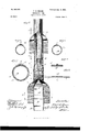
- Figure 1 is a view in elevation of a single-tube pneumatic tire embodying my improvements.
- Fig. 2 is a view illustrating the various steps in the manufacture of the tire in accordance with my in- Fig. 3 is a cross-section on the line Fig. 4c is a cross-section on the Fig. 5 is a cross-section on Fig. 6 is a cross-section vention. 3 of Fig. 2.
- Fig. 7 is a cross-section on the line 7 of Fig. 2.
- Fig. 8 is a view of the endless band of fabric, and
- Fig. 9 is a view of the endless outer rubber band which constitutes the outer layer of the tubing.
- A represents the inner tube, which may be made in any manner found most desirable, either by joining a calendered strip into tubular form or by the well-known method of producing seamless tubing on a tubing-machine or otherwise.
- the tube A may, moreover, he of any thickness and size desired.
- the inner tube will ordinarily be comparatively thin, with an internal diameter of, say, one inch or alittle more, While in the case of an automobile-tire the tubing will be ordinarily much thicker and of greater diameter.
- the tube A is vulcanized in a straight length and preferably upon a straight mandrel.
- I may either weave a tube with the diameter desired in the band and cut the tube into transverse sections of the desired Width of the band, or I'may take a strip of fabric of the desired Width and cut either on the bias or straight and join the ends to produce an endless band of the proper diameter by stitching, cementing, lacing, or otherwise.
- This endless band,cemented as described is placed beneath the tube A, which is firmly rolled down upon the band, so as to be united to the latter along its central line, as indicated in crosssection in Fig. 3.
- the free edgest of the band 0 are then brought together, as indicated in Fig.
- the inner tube A may be made and tested for. flaws before incorporating it in the tire.
- the strain-resisting fabric C is at no time subjected to the deleterious effect of vulcanization.
- the outer tube or layer may be vulcanized under the most favorable conditions, as on a drum, and all the elements of the tire may be, and do become, securely united to each other by the simple operations of inflating and applying hand-roller pressure.
- the puncture can be repaired in the same manner now practiced with other single -tube tiresnamely, by injecting cement into the puncture or by inserting and vulcanizing a patch or by introducing a plug.
- the method of producing a single-tube pneumatic tire which consists in forming an endless inner tube of vulcanized rubber, applying and cementing thereto an endless band of fabric, stitching the edges of the fabric to form a tube, cementing upon the joined edges a protection-strip of fabric, and applying to the tube of fabric and cementing thereto a tube of vulcanized rubber, substantially as described' 2.
- the method of producing an inner vulcanized tube with an unvulcanized endless tubular covering of fabric cemented thereto which consists in first form ing an endless vulcanized rubber tube, then forming an endless band of fabric having cement upon one surface, firmly uniting the rubber tube to the band along the center of the latter, uniting, as by sewing, the edges of the band to form an endless tube, and thereupon inflating the inner tube, to cause it to be united to the remaining surface of the hand, all as set forth.
- a pneumatic tire comprising the inner endless vulcanized rubber tube A, provided with a valve D, the outer endless vulcanized rubber tube F, the intermediate unvulcanized reinforcing fabric 0, having its edges united to form a tube, and the joint-protecting strip E, the elements being united together by cement Without vulcanization, substantially as described.
- a single-tube pneumatic tire comprising an inner vulcanized endless tube of rubber, an outer vulcanized endless band havingscribed.
Landscapes
- Engineering & Computer Science (AREA)
- Mechanical Engineering (AREA)
- Tyre Moulding (AREA)
- Tires In General (AREA)
Description
No. 663,633. Patented Dec. II, I900. F. H. MASON.
PNEUMATIC TIRE.
(Application filed Mar. 9, 1900.)
(No Model.) 2 Sheets-Sheet I.
flan if I 425077,
(No Model.)
F. H. MASON.
PNEUMATIC TIRE.
(Application filed Mar. 9, 1900.)
Patented Dec. ll, I900.
2 Sheets-Sh6et z.
flQR/ZZ m: ucnms PEYEHS co. FHOTO LITHO. wAsulNoToN. u. c
NITE
FRANK H. MASON,
OF AKRON, OHIO.
PNEUMATIC TIRE.
.SPECIFIGATION forming part of Letters Patent No. 663,633, dated December 0- Application filed March 9, l. 9 00.
T0 at whom it may concern.-
Be it known that I, FRANK H. MASON, a citizen of the United States, residing at Akron, in the county of Summit and State of Ohio, haveinvented a new and useful Improvement in Pneumatic Tires, of which the following is a specification.
My invention relates to an improvement in pneumatic tires of the class which employ in their construction rubber and fabric,and more particularly to that class of pneumatic tires known as singletube tires. The pneumatic tires embodying my invention may be used on bicycles or other velocipedes, as well as on vehicle-wheels of all kinds-such as antomobiles, wagons, carriages, motocycles, 8:0.
Heretofore in the construction of the single tube pneumatic tire it has been deemed essential in practice to build up the tire-tube with an inner lining or tube of rubber, an intermediate layer of strain-resisting fabric, and an outer tubing of rubber, and thereupon to join the ends of the several component partsv together and effect the permanent union at the joints and between the component parts by vulcanization, to which end the rubber tubes referred to were employed in an un vulcanized state in building the tire. It has been urged, however, that the act of vulcanizin g the cloth or fabric which constitutes the strain-resist ing elementor the tire has a deleterious effect upon the fiber,wl1ereby it does not present to the utmost or even to the required degree the strength and rigidity desirable in this element. It is further recognized, moreover, among tire-manufacturers that the act of producing the joint whereby the straight tubing is formed into an annulus is where the ele- Serial No. 7,975. (No model.)
the forms of double-tube tire the earlier construction of the Dunlop employed an inner detachable tube of vulcanized rubber made endless and an outer detachable cover in the form of an endless band of rubber having a layer of fabric cemented or vulcanized upon itsinnersnrface. It has, so far as Iam aware, however, been deemed impracticable to use in the construction of single-tube tires the method of combining the elements practiced in the manufacture of the double-tube detachable tire.
The object of my ll'IVGIllJlOIl is to produce a single-tube tire for bicycles and other vehicles the elements of which shall be united into a single endless tube without employing vulcanization for this purpose and without any vulcanization subsequent to the union of the elements.
The further object of my invention is to produce a single-tube tire which shall be free of any of the objections above pointed out and which may be more economically produced than other single-tube tires now known.
To these ends myinventionconsistsinasingle-tube tire composed of a vulcanized inner endless air-tube, an intermediate tubular endless layer of fabric, and an outer endless tube of vulcanized rubber, the parts being united by cementing and without vulcanization.
My invention further consists in the preferred method of assembling and uniting the elements of the tire, as hereinafter set forth, andmy invention further consists in the preferred general and specific details of construction and combinations of parts, all as hereinafter set forth.
In the drawings, Figure 1 is a view in elevation of a single-tube pneumatic tire embodying my improvements. Fig. 2 is a view illustrating the various steps in the manufacture of the tire in accordance with my in- Fig. 3 is a cross-section on the line Fig. 4c is a cross-section on the Fig. 5 is a cross-section on Fig. 6 is a cross-section vention. 3 of Fig. 2. line 4 of. Fig. 2. the line 5 of Fig. 2.
on the line 6 of Fig. 2. Fig. 7 is a cross-section on the line 7 of Fig. 2. Fig. 8 is a view of the endless band of fabric, and Fig. 9 is a view of the endless outer rubber band which constitutes the outer layer of the tubing.
In explanation of Fig. 2 of the drawings it should be understood that the length of tubing embodied in said figure is a section of an endless tire and that the various cross-sectional views illustrate the step-by-step condition of the tire being manufactured.
A represents the inner tube, which may be made in any manner found most desirable, either by joining a calendered strip into tubular form or by the well-known method of producing seamless tubing on a tubing-machine or otherwise. The tube A may, moreover, he of any thickness and size desired. Thus for bicycletires the inner tube will ordinarily be comparatively thin, with an internal diameter of, say, one inch or alittle more, While in the case of an automobile-tire the tubing will be ordinarily much thicker and of greater diameter. The tube A is vulcanized in a straight length and preferably upon a straight mandrel. Either before or after vulcanizing the tube is cut to the length desired in the pneumatic tire, and then after vulcanizing the ends are joined by telescoping one into the other, as illustrated at -B, Fig. 2, the joint being made secure by the use of cement. It will involve no departure from my invention, however, to join the ends of the tube A before vulcanization or in any other suitable manner after vulcanization. The inner rubber tube A having thus been produced, I next prepare an endless band of suitable fabric, such as duck, by forming it into an endless strip of suitable Width, more than enough to envelop the tube A, and apply to the inner face of this fabric a coating of rubber cement. To make the fabric 0, I may either weave a tube with the diameter desired in the band and cut the tube into transverse sections of the desired Width of the band, or I'may take a strip of fabric of the desired Width and cut either on the bias or straight and join the ends to produce an endless band of the proper diameter by stitching, cementing, lacing, or otherwise. This endless band,cemented as described, is placed beneath the tube A, which is firmly rolled down upon the band, so as to be united to the latter along its central line, as indicated in crosssection in Fig. 3. The free edgest of the band 0 are then brought together, as indicated in Fig. 4, and stitched on an ordinary stitching-machine to produce an endless tube of fabric internally solutioned and presenting along one inner circumferential face the flaps t. The outer sides of these flaps t are thereupon provided with solution and the inner tube is inflated through the medium of the valve D, which'had previously been supplied to the inner tube in the usual manner. The effect of inflation is firmly to cement the inner tube to the tube of fabric. At this time also the flaps t are rolled down, and over the flaps is placed a strip E of fabric which is solutioned on its under face. This is illustrated in Fig. 6. I now prepare an endless band of vulcanized rubber having the thickness desired in the outer rubber covering of the tube and, if desired, also made thicker in one part than in another, this band being by preference made endless before vulcanization, after the manner common in the outer covering of detachable tires. The innersurface of this band F is coated with solution and applied to the partially-completed tire-tube in such a manner that the meeting edges of the band are presented at the seating side of the tire. To make the union more perfect, the elements are rolled firmly together while the inner tube is inflated. The inflating of the inner tube for this purpose may, however,be dispensed with.
Where the exigencies require the use of greater reinforcement than can be obtained with a single layer of fabric, more than one layer may be employed, and by preference each layer is independently sewed up into an endless tube before the next layer is applied thereto, and by preference also the line of the joint produced by sewing is not made coincident in the various layers. It will, however, be no departure from my invention to unite several layers in a tube in one sewing operation. Where the nature of the fabric forbids sewing to be practiced, other means of effecting the joint which forms the fabric into an endless tube may be employed, and such other means may be used in any event.
In a tire embodying the above construction it will be observed that the inner tube A may be made and tested for. flaws before incorporating it in the tire. The strain-resisting fabric C is at no time subjected to the deleterious effect of vulcanization. The outer tube or layer may be vulcanized under the most favorable conditions, as on a drum, and all the elements of the tire may be, and do become, securely united to each other by the simple operations of inflating and applying hand-roller pressure.
In case of puncturing the tire in use the puncture can be repaired in the same manner now practiced with other single -tube tiresnamely, by injecting cement into the puncture or by inserting and vulcanizing a patch or by introducing a plug.
What I claim as new, and desire to secure by Letters Patent, is-
1. The method of producing a single-tube pneumatic tire, which consists in forming an endless inner tube of vulcanized rubber, applying and cementing thereto an endless band of fabric, stitching the edges of the fabric to form a tube, cementing upon the joined edges a protection-strip of fabric, and applying to the tube of fabric and cementing thereto a tube of vulcanized rubber, substantially as described' 2. In the manufacture of a pneumatic tire, substantially as described, the method of producing an inner vulcanized tube with an unvulcanized endless tubular covering of fabric cemented thereto, which consists in first form ing an endless vulcanized rubber tube, then forming an endless band of fabric having cement upon one surface, firmly uniting the rubber tube to the band along the center of the latter, uniting, as by sewing, the edges of the band to form an endless tube, and thereupon inflating the inner tube, to cause it to be united to the remaining surface of the hand, all as set forth.
A pneumatic tire, comprising the inner endless vulcanized rubber tube A, provided with a valve D, the outer endless vulcanized rubber tube F, the intermediate unvulcanized reinforcing fabric 0, having its edges united to form a tube, and the joint-protecting strip E, the elements being united together by cement Without vulcanization, substantially as described.
4. A single-tube pneumatic tire, comprising an inner vulcanized endless tube of rubber, an outer vulcanized endless band havingscribed.
FRANK H. MASON.
In presence of- D. W. LEE, A. D. BACOI.
Priority Applications (1)
| Application Number | Priority Date | Filing Date | Title |
|---|---|---|---|
| US797500A US663633A (en) | 1900-03-09 | 1900-03-09 | Pneumatic tire. |
Applications Claiming Priority (1)
| Application Number | Priority Date | Filing Date | Title |
|---|---|---|---|
| US797500A US663633A (en) | 1900-03-09 | 1900-03-09 | Pneumatic tire. |
Publications (1)
| Publication Number | Publication Date |
|---|---|
| US663633A true US663633A (en) | 1900-12-11 |
Family
ID=2732192
Family Applications (1)
| Application Number | Title | Priority Date | Filing Date |
|---|---|---|---|
| US797500A Expired - Lifetime US663633A (en) | 1900-03-09 | 1900-03-09 | Pneumatic tire. |
Country Status (1)
| Country | Link |
|---|---|
| US (1) | US663633A (en) |
Cited By (1)
| Publication number | Priority date | Publication date | Assignee | Title |
|---|---|---|---|---|
| US6418991B1 (en) * | 1999-12-27 | 2002-07-16 | Michael L. Trice | Puncture proof inner tube |
-
1900
- 1900-03-09 US US797500A patent/US663633A/en not_active Expired - Lifetime
Cited By (1)
| Publication number | Priority date | Publication date | Assignee | Title |
|---|---|---|---|---|
| US6418991B1 (en) * | 1999-12-27 | 2002-07-16 | Michael L. Trice | Puncture proof inner tube |
Similar Documents
| Publication | Publication Date | Title |
|---|---|---|
| US7438961B2 (en) | Plies sleeve for use in forming an elastomeric tire | |
| CN113928059A (en) | Radial tire and method of joining carcass layer thereof | |
| US20170239995A1 (en) | Improved tire belt construction | |
| US663633A (en) | Pneumatic tire. | |
| US497971A (en) | Island | |
| US2010767A (en) | Method of making pneumatic tires | |
| US1141708A (en) | Method of making tires. | |
| US2401045A (en) | Method of producing a renewable tread tire | |
| US1258506A (en) | Process of making tires. | |
| US1318119A (en) | wallace | |
| US604636A (en) | Device for repairing rubber tires | |
| US453550A (en) | John boyd dunlop | |
| US603605A (en) | Pneumatic tire | |
| US1828925A (en) | Joint and methods of making the same | |
| US476681A (en) | Pneumatic tire | |
| US646710A (en) | Pneumatic tire. | |
| US675164A (en) | Pneumatic tire and method of making same. | |
| US467502A (en) | Pneumatic tire for bicycles | |
| US1317665A (en) | Clifford | |
| US487522A (en) | William folding | |
| US533251A (en) | Alexander straus | |
| US548675A (en) | Alexander straus | |
| US1171449A (en) | Process of retreading old auto-tires. | |
| US599802A (en) | Pneumatic tire | |
| US643826A (en) | Pneumatic tire. |