US661897A - Machine-gun. - Google Patents
Machine-gun. Download PDFInfo
- Publication number
- US661897A US661897A US1576500A US1900015765A US661897A US 661897 A US661897 A US 661897A US 1576500 A US1576500 A US 1576500A US 1900015765 A US1900015765 A US 1900015765A US 661897 A US661897 A US 661897A
- Authority
- US
- United States
- Prior art keywords
- bolt
- barrel
- cartridge
- tubular
- opening
- Prior art date
- Legal status (The legal status is an assumption and is not a legal conclusion. Google has not performed a legal analysis and makes no representation as to the accuracy of the status listed.)
- Expired - Lifetime
Links
Images


Classifications
-
- F—MECHANICAL ENGINEERING; LIGHTING; HEATING; WEAPONS; BLASTING
- F41—WEAPONS
- F41A—FUNCTIONAL FEATURES OR DETAILS COMMON TO BOTH SMALLARMS AND ORDNANCE, e.g. CANNONS; MOUNTINGS FOR SMALLARMS OR ORDNANCE
- F41A7/00—Auxiliary mechanisms for bringing the breech-block or bolt or the barrel to the starting position before automatic firing; Drives for externally-powered guns; Remote-controlled gun chargers
- F41A7/08—Drives for externally-powered guns, i.e. drives for moving the breech-block or bolt by an external force during automatic firing
Description
Patented Nov. l3, I900.
H., H. 'l oLL. MACHINE GUN. (Application filed May 7 1900.
4 Sheets-Sheet (No Model.)
Patented Nov. I3, I900. H. H. TOLL.
MACHINE GUN.
(Application filed May 7, 1900.)
(No Model.)
7% mf w& g IIIIII X 4 SheetsSheet 3.
Patented Nov. [3-, I900.
M o 9 L L w 0 m T d "b HM .m t Mm M p u 7 9 8 m m 6 M M 0 0 N N Patented Nov. I3, I900.
N0. 6BL897.
H. H. TULL..
MACHINE GUN.
(Application filed May 7, 1900.
4 Sh'eetsSheei 4.
{No Model.)
Wilgzsses @J imam grates 'ATENT trio's.
HERMAN H. TOLL, OF CLARINDA, IOVA.
MACHINE-GUN.
SPECIFICATION formingpart of Letters Patent No. 661.897, dated November 13, 1900. Application filed May 7. 1900 Serial No. 15.765. LNo modei.)
To all whom, it may concern:
Be it known that I, HERMAN H. TOLL, acitizen of the United States, residing at Olarinda, in the county of Page and Stale of Iowa, have invented a new and useful Machine-Gun, of which the following is a specification.
My invention is an improved machine-gun; and it consists in the peculiar construction and combination of devices hereinafter fully set forth, and pointed out in the claims.
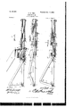
In the accompanying drawings, Figure l is a side elevation, partly in section, of a machine-gun embodying my improvements organized for service. Fig. 2 is a detail sectional view of a portion of the barrel, the tubular bolt, and the operating rock-shaft and connections, the parts being in position as sumed when the cartridge is supplied to the bolt. Fig. 3 is a similar view of the same, the parts being in position when the cartridge is loaded into the breech of the barrel by the bolt and just before it is fired. Fig. 4 is a similar view of the same,showing the positions assumed by the parts after the cartridge has been fired and while the cartridge-shell is being withdrawn from the barrel. Fig. 5 is a top plan view, partly in sect-ion. Fig. 6 is a vertical transverse sectional view taken through the magazine and the bolt. Fig. 7 isa detail side elevation. Fig. 8 is adetail perspective view of the cartridge-holder for charging a plurality of magazines simultaneously.
In service I contemplate the employment of a number of my improved machine-guns in a single arm organized for simultaneous operation, as shown in Figs. 1 and 5.
I will first describe my improved machinegun per se. The barrel 1 is of the usual construction and may be mounted in any suitable manner. As here shown, the barrel is supported between a pair of rearward-extending arms or plates 2, which form in their 0pposing sides guideways 3 for a tubular cy1indrical combined bolt, carrier, and breechpiece 4, which for brevity of expression I will hereinafter refer to as a tubular bolt. The said tubular bolt fits accurately and is adapted to slide longitudinally on the breech of the barrel and is closed at its rear end, as at 5, and provided with a projecting firingstud 6. Flanges 7 project laterally from the side of the tubular bolt and operate in the guideways 3. length is madein the upper side of the tubular bolt, near the rearend thereof, and a discharge-opening 9 of suitable length is made in the lower side of the tubular bolt, near the front end thereof, the length of the said tubular bolt somewhat exceeding the combined lengths of the said openings 8 9, so that the same are disposed in different vertical planes and do not overlap. A cam 10 is formed centrally on the lower side of the tubular bolt. The cartridge-shell ejector ll forms the section of a cylinder and is disposed in the lower side of the tubular bolt, in rear of the discharge-opening 9 thereof, is provided at its front end on its upper side with an engaging flange or shoulder 12, which is adapted to engage the base-rim of the cartridge-shell, and is provided on its lower side with a dovetailed spline 13, which operates in a dovetailed groove 14, disposed longitudinally in the lower side of the tubular bolt. The closed breech 5 of the tubular bolt has an opening 15 of appropriate size and shape to admit of the longitudinal play of the ejector in the tubular bolt.
The operation of the gun or firearm is as follows: The tubular bolt being drawn outward on the breech of the barrel, so as to uncover the feed-opening 8, a cartridge may be inserted in the tubular bolt and upon the ejector, which forms the lower side thereof, through the opening 8, as shown in Fig. 2. The tubular bolt being then moved forward in sliding upon the breech of the barrel carries the cartridge with it, the firing-stud bearing on the center of the cap and moving the cartridge into the breech of the barrel, as shown in Fig. 3. At the instant that the front end of the ejector engages the breech of the barrel the motion of the ejector is arrested and the tubular bolt continuing to move forward completes its forward movement independently of the ejector, the latter being caused to extend beyond the breech of the tubular bolt, as shown in Fig. 3. As the tubular bolt reaches the forward limit of its movement its firing-stud 6 engages and compresses the center cap in the base of the cartridge-shell and discharges the same by percussion, as will be understood. On the ensuing reverse movement of the tubular bolt A feed-opening 8 of suitable the ejector 12 being in engagement with the base-rim of the cartridge-shell and being in contact with the closed front end of the dovetailed groove'la moves rearward with the tubular bolt, thereby withdrawing the empty cartridge-shell from the breech of the barrel, the empty shell droppi ng through the opening 9 as the latter is uncovered by the recession of the tubular bolt. I do not limit myself to the use of the firing-stud here shown, as the same mightin some instances cause cartridges of the kind now in common use to be exploded while being placed in the breech of the gun. I have shown and described the firing-stud as one means for firing the cartridges; but I would have it understood that any suitable firing mechanism may be used in connection with my improvements. It will be understood that any suitable means may be employed for thus actuating lhe'tubular bolt. I will now describe means which are adapted to this purpose. A rock-shaft 1G is journaled transversely with relation to the arms or plates 2 and in bearings 17 at the rear ends thereof, and said rock-shaft is provided with a rocking arm 18, which is connected to the breech of the tubular bolt by a connectingrod 19, the latter being jointed, as at 20, pivotally to the rocking arm and pivota lyjointed at its front end to rearwardprojecting lugs or cars 21, with which the breech of the tubular bolt is provided. It willbe understood that by imparting rocking motion to the shaft 16, which may be done by a suit-able handle or lever, reciprocating motion, such as before described, may be communicated to the tubular bolt and the arm loaded, fired, and the cartridge-shell ejected in the manner hereinbefore described.
I will now describe means for automatically loading the gun. A magazine 22 rises from one side of the gun at a point opposite the feed-opening 8 when the tubular bolt is at the rearward limit of its movement. The magazine may be supported by any suitable means. I have here shown it as attached to and supported on one of the plates 2. The
' magazine is so disposed that the cartridges therein descend by gravity, and the magazine is provided at its lower side with afeed-chamber 23, of suitable shape and dimensions, in which is mounted a revoluble feeder 24. The latter is provided with a series of faces or seats 25, longitudinally disposed therein and concentric with its axis, which faces or seats are adapted to receive the cartridges successively as the latter descend by gravity in the magazine. The feeder thus forms a gate or stop to arrest the descent of the cartridges and to regulate the admission thereof one by one into the tubular bolt through the opening 8, this being accomplished by partly turning the revoluble feeder in the direction indicated by the arrow in Fig. 8 when the tubular bolt reaches the rearward limit of its Stroke.
I will now describe means forautomatically partly rotating the revolnble feeder at each rear stroke of the tubular bolt. The revoluble feeder is provided with ratchet-teeth 26 at one end,which correspond in number with the faces or recesses 25. A bell-crank lever 27 is fulcrumed to a suitable support, as at 28, (shown in Fig. 6,) the lower arm 29 of which bell-crank lever extends under the tubular bolt and is adapted to be engaged by the cam 10 on the under side of the latter and depressed thereby on the reverse stroke of the tubular bolt. A pawl 30 (indicated in dotted lines in Fig. 6 and shown in full lines in Figs. 2and 7) is pivotally connected to the arm 31. of said bell-crank lever and is adapted to engage the ratchet-teeth 26 successively, and hence partly turn the revolnble feeder at each reverse stroke of the tubular bolt a distance sufficient to cause the revoluble feeder to discharge the cartridge carried thereby into the breech end of the tubular bolt, as will be understood. A spring 32 returns the bell-crank lever to its initial position (shown in Fig. 6) as said bell-crank lever is disengaged by the cam 10 as the tubular bolt moves forward, thereby engaging the pawl 30 with the next successive ratchettooth.
My improved machine-gun is highly efficient when used singly and is effective in discharging shots with great rapidity, a single movement back and forth of the rockshaft sufficing for the loading, firing, and discharge of the cartridge-shell and reloading for the next shot. Under certain conditions, however, I propose to employ a num ber of my machine-guns in a single arm for field, naval, and other service, and in Fig. 1 of the drawings I have shown a machine-gun thus organized, which I will now describe.
A shield or casing 33, which is of substantially cylindrical form, contains the guns, which are in this figure designated individually by the letter A. Any desired numberof the guns may be used and the same are disposed one above another in horizontal tiers. The guns are provided with trunnions 34, which operate in vertical slots 35, with which the vertical supporting-bars 36 are provided. Cam-levers 37 are fulcrumed on the said supporting-bars and are provided with eccentrically-disposed cam slots 88, which engage the projecting ends ofthe trunnions, and the said. cam levers have rearward extending arms 39, which are connected together in series by a vertically-disposed rod 40. The rock-shafts 16 at the rear ends of the guns are common to each horizontally-disposed row thereof, said rock-shafts being journaled in vertically-disposed supporting-bars 4:2 and forming the pivots of the guns, upon which they turn individually in vertical planes, so as to concentrate or diffuse their fire vertically, as will be understood. The said rockshafts 16 are provided with sprocket-pinions 4L3, engaged on one side by one lead of an endless sprocket-chain 4L4. Said sprocket-chain IIO engages an operating sprocket wheel 45, which is actuated first in one direction and then in the reverse direction through a partial rotation by a hand-lever 46, which is connected thereto by a pitman 47, rocking motion being hence communicated to the rockshaft 16 through said wheel 45, sprocket-pinions 43, and sprocket-chain 44, as will be understood, thus actuating the firing mechanism ofallthegunssimultaneously,and hence causing the same to fire in volleys, as will be understood. A hand-lever 48 is connected to the rod 40 by a rod 4E9 and links 50 51 52, said links 50 52 being levers fulcrumed on suitable supports, as shown. In this embodiment of myinvention the magazines of the respective guns incline rearwardly, as shown, so that their upper ends are accessible and to enable them to be readily charged. The connected simultaneously-operated cam-levers 37 for raising and lowering the trunnions of the guns concent rate or scatter their fire vertically, as may be required in action.
I do not limit myself to the means herein shown and described for operating a number of my machine-guns in unison, as any suit,- able means may be substituted in lieu thereof.
The shield or casing 33 maybe pivotally mounted on a suitable carriage, as shown in Fig. l. i
In Fig. 8 I illustrate a cartridge-case having a plurality of sections 53, which should correspond in number with the guns in a horizontal row and are adapted at their lower ends to register with the upper feed ends of the magazines. Each of the said sections is provided at its lower end With a hinged valve or gate 54, operated by a rod 55, connected to and actuated by a rock-arm 56 of a rock-shaft 57, which is mounted on a plate 58, that connects the upper ends of the sections 53 in serie The said rock-shaft 57 has an operating-arm 59, by turning which the valves 54 may be simultaneously opened, so as to discharge the cartridges in the sections 53 into the magazines of the guns. A locking-bolt 60 is employed to keep the valves 5% normally closed, the said locking-bolt engaging the operating-arm 59, as shown.
Having thus described my invention, I claim-- 1. In a firearm, the combination of a barrel and a bolt adapted to slide telescopically thereon, to contain a cartridge and load the same into the barrel as the bolt moves forward, said bolt having an opening in one side through which the cartridge is fed thereto, and another opening, in advance of the former, covered by the barrel as the bolt moves forward and uncovered by the barrel as the bolt recedes, through which latter opening the shell of the exploded cartridge is ejected, substantially as described.
2. In a firearm, the combination of a barrel, a bolt adapted to slide telescopically.
thereon, to contain a cartridge and load the same into the barrel as the bolt moves forward, said bolt having an opening in one.
side, through which the cartridge is fed thereto, and another opening in advance of the former, covered by the barrel as the bolt moves forward and uncovered by the barrel the bolt recedes, through which latter opening the shell of the exploded cartridge is ejected, and an ejector movable longitudinally with said bolt on the forward stroke of the latter, said bolt and ejector having coacting stops, to withdraw said extractor from the breech of the barrel on the reverse stroke of the bolt, substantially as described.
3. In a firearm, the combination of a barrel, a bolt adapted to slide telescopically thereon and to carry and load a cartridge into the barrel, said bolt having an opening, uncovered by the barrel. on the reverse movement of the bolt, in advance of the seat of the cartridge on the initial movement of the bolt, an extractor movable with the bolt and also movable longitudinally independently of the bolt, and stops to limit said movement of said extractor, substantially as described.
4. In a firearm, the combination of a barrel, a bolt adapted to slide telescopically thereon, to carry a cartridge and load the same into the barrel as said bolt moves forward, said bolt having an opening, in advance of the seat of the cartridge on the initial movement of the bolt, and uncovered by the barrel on the reverse movement of the bolt, and an extractor, movable with the bolt and also movable longitudinally independent of the bolt, said extractor having a flange to engage the base-rim of the cartridge-shell and said extractor being adapted to contact with the barrel, on the forward stroke of the bolt, whereby the forward movement of said extractor is arrested, prior to that of the bolt, and said extractor and bolt having coacting stops, to move said extractor rearward with said bolt, substantially as described.
5. In a firearm, the combination of a barrel, a bolt adapted to slide telescopically thereon and to carry and load a cartridge into the barrel, said bolt having an opening, uncovered by the barrel on the reverse movement of the bolt, in advance of the seat of the cartridge on the initial movement of the bolt, an extractor movable with the bolt and also movable longitudinally independently of the bolt, stops to limit said movement of said extractor, and means to feed acartridge singly to the bolt on the rear stroke of the latter, substantially as described.
6. In a firearm, the combination of a barrel, a bolt adapted to slide telescopically thereon and to carry and load a cartridge into the barrel, said bolt having an opening, uncovered by the barrel on the reverse movement of the bolt, in advance of the seat of the cartridge on the initial movement of the bolt, an extractor movable with the bolt and also movable longitudinally, independently to the bolt on the rear stroke of the latter and means to actuate said bolt, substantially as described.
7. In a firearm, the combination of a barrel, a bolt adapted to slide telescopically thereon, and to carry and load a cartridge into the barrel, said bolt having an opening, uncovered by the barrel, on the reverse movement of the bolt, in advance of the seat of the cartridge on the initial movement of the bolt, an extractor movable with the bolt and also movable longitudinally independently of the bolt, means to feed cartridges singly to the bolt on the rear stroke of the latter and arock-shaft havingarock-arm, and arod connecting said rock-shaft to said bolt, substantially as described.
8. In a firearm, the combination of a barrel, a bolt adapted to slide telescopically thereon and to carry and load a cartridge into the barrel, said bolt having an opening uncovered by the barrel, on the reverse movement of the bolt, in advance of the seat of the cartridge on the initial movement of the bolt, an extractor movable with the bolt and also movable longitudinally independently thereof, stops to limit said movement of said extractor, means to feed cartridges singly to the bolt on the rear strokes of the latter, an actuating-shaft and connections between the former and the bolt, substantially as described.
9. In a firearm, the combination of a barrel, a bolt adapted to slide telescopically thereon and to carry and load a cartridge into .of the bolt, means to feed cartridges singly l the barrel, said bolt having an opening uncovered by the barrel on the reverse movement of the bolt, in advance of the seat of the cartridge on the initial movement of the bolt, an extractor movable with the bolt and also movable longitudinally independently of the bolt, stops to limit said movement of said extractor, a magazine, a revoluble feeder, and connections actuated by the bolt to operate said revoluble feeder, substantially as described.
10. In a firearm, the combination of a barrel, a bolt adapted to slide telescopically thereon and to carry and load a cartridge into the barrel, said bolt having an opening uncovered by the barrel on the reverse movement of the bolt in advance of the seat of the cartridge on the initial movement'of the bolt, and also having a cam, an extractor movable with the bolt and also movable longitudinally, independently of the bolt, stops to limit said movement of said extractor, a magazine, a revoluble feeder to convey cartridges singly from the magazine to the bolt, said revoluble feeder having ratchet-teeth, a lever actuated by the cam of the tubular bolt, and a pawl carried by said lever and engaging the ratchet-teeth of said revoluble feeder, substantially as described.
In testimony that I claim the foregoing as my own I have hereto affiXed my signature in the presence of two witnesses.
HERMAN H. TOLL.
Witnesses:
E. B. ToLL, A. B. CLARK.
Priority Applications (1)
| Application Number | Priority Date | Filing Date | Title |
|---|---|---|---|
| US1576500A US661897A (en) | 1900-05-07 | 1900-05-07 | Machine-gun. |
Applications Claiming Priority (1)
| Application Number | Priority Date | Filing Date | Title |
|---|---|---|---|
| US1576500A US661897A (en) | 1900-05-07 | 1900-05-07 | Machine-gun. |
Publications (1)
| Publication Number | Publication Date |
|---|---|
| US661897A true US661897A (en) | 1900-11-13 |
Family
ID=2730460
Family Applications (1)
| Application Number | Title | Priority Date | Filing Date |
|---|---|---|---|
| US1576500A Expired - Lifetime US661897A (en) | 1900-05-07 | 1900-05-07 | Machine-gun. |
Country Status (1)
| Country | Link |
|---|---|
| US (1) | US661897A (en) |
Cited By (6)
| Publication number | Priority date | Publication date | Assignee | Title |
|---|---|---|---|---|
| US2495822A (en) * | 1945-05-09 | 1950-01-31 | United Shoe Machinery Corp | Firing mechanism for use in armed mounts |
| US2545217A (en) * | 1945-07-18 | 1951-03-13 | Earl C Walker | Rocket launcher |
| US3362293A (en) * | 1965-03-02 | 1968-01-09 | Bofors Ab | Round feeding mechanism for automatic guns |
| US4069740A (en) * | 1975-08-14 | 1978-01-24 | Werkzeugmaschinenfabrik Oerlikon-Buhrle Ag | Automatic weapon equipped with at least two cartridge magazines |
| US4418607A (en) * | 1977-04-21 | 1983-12-06 | Hughes Helicopters, Inc. | Single barrel externally powdered gun |
| US4481861A (en) * | 1980-08-05 | 1984-11-13 | Societe Cassanelli & Cie | Fire adjustment device designed to be mounted on the end of a gun barrel |
-
1900
- 1900-05-07 US US1576500A patent/US661897A/en not_active Expired - Lifetime
Cited By (6)
| Publication number | Priority date | Publication date | Assignee | Title |
|---|---|---|---|---|
| US2495822A (en) * | 1945-05-09 | 1950-01-31 | United Shoe Machinery Corp | Firing mechanism for use in armed mounts |
| US2545217A (en) * | 1945-07-18 | 1951-03-13 | Earl C Walker | Rocket launcher |
| US3362293A (en) * | 1965-03-02 | 1968-01-09 | Bofors Ab | Round feeding mechanism for automatic guns |
| US4069740A (en) * | 1975-08-14 | 1978-01-24 | Werkzeugmaschinenfabrik Oerlikon-Buhrle Ag | Automatic weapon equipped with at least two cartridge magazines |
| US4418607A (en) * | 1977-04-21 | 1983-12-06 | Hughes Helicopters, Inc. | Single barrel externally powdered gun |
| US4481861A (en) * | 1980-08-05 | 1984-11-13 | Societe Cassanelli & Cie | Fire adjustment device designed to be mounted on the end of a gun barrel |
Similar Documents
| Publication | Publication Date | Title |
|---|---|---|
| US1332060A (en) | Recoll-operated ordnance | |
| US661897A (en) | Machine-gun. | |
| US454403A (en) | o odkolek | |
| US642018A (en) | Automatic machine-gun. | |
| US789142A (en) | Firearm. | |
| US672300A (en) | Magazine-pistol. | |
| US863101A (en) | Automatic gun | |
| US282553A (en) | Machine-gun | |
| US1504393A (en) | Cartridge-feeding mechanism for automatic guns | |
| US1839621A (en) | Automatic firearm | |
| US544657A (en) | Territory | |
| US390114A (en) | bugton | |
| US638677A (en) | Magazine-gun. | |
| US459828A (en) | The hor | |
| US809640A (en) | Gun. | |
| US319595A (en) | maxim | |
| US1003790A (en) | Gun. | |
| US10520A (en) | Improvement in fire-arms | |
| US206365A (en) | Improvement in machine-guns | |
| US121277A (en) | Improvement in machine-guns | |
| US781503A (en) | Automatic gun. | |
| US591155A (en) | Recoil-operated gun | |
| US154596A (en) | Improvement in machine-guns | |
| US632235A (en) | Magazine-firearm. | |
| US33813A (en) | Improvement in repeating ordnance, sgc |