US6602448B1 - Graded plastic optical element and method for producing thereof - Google Patents
Graded plastic optical element and method for producing thereof Download PDFInfo
- Publication number
- US6602448B1 US6602448B1 US09/461,482 US46148299A US6602448B1 US 6602448 B1 US6602448 B1 US 6602448B1 US 46148299 A US46148299 A US 46148299A US 6602448 B1 US6602448 B1 US 6602448B1
- Authority
- US
- United States
- Prior art keywords
- bore
- index
- tube
- refractive index
- preform
- Prior art date
- Legal status (The legal status is an assumption and is not a legal conclusion. Google has not performed a legal analysis and makes no representation as to the accuracy of the status listed.)
- Expired - Lifetime
Links
- 230000003287 optical effect Effects 0.000 title claims abstract description 9
- 239000004033 plastic Substances 0.000 title claims description 7
- 229920003023 plastic Polymers 0.000 title claims description 7
- 238000004519 manufacturing process Methods 0.000 title description 4
- 239000002019 doping agent Substances 0.000 claims abstract description 84
- 239000000463 material Substances 0.000 claims abstract description 82
- 239000013307 optical fiber Substances 0.000 claims abstract description 55
- 238000000034 method Methods 0.000 claims abstract description 50
- 229920002313 fluoropolymer Polymers 0.000 claims abstract description 49
- 239000004811 fluoropolymer Substances 0.000 claims abstract description 49
- 238000009792 diffusion process Methods 0.000 claims abstract description 30
- 238000010438 heat treatment Methods 0.000 claims abstract description 28
- 239000007788 liquid Substances 0.000 claims abstract description 26
- 230000004907 flux Effects 0.000 claims description 10
- 229920001577 copolymer Polymers 0.000 claims description 9
- 230000005540 biological transmission Effects 0.000 claims description 7
- 229920001343 polytetrafluoroethylene Polymers 0.000 claims description 6
- 230000009477 glass transition Effects 0.000 claims description 5
- -1 polytetrafluoroethylene Polymers 0.000 claims description 3
- 239000013306 transparent fiber Substances 0.000 claims 3
- YSYRISKCBOPJRG-UHFFFAOYSA-N 4,5-difluoro-2,2-bis(trifluoromethyl)-1,3-dioxole Chemical compound FC1=C(F)OC(C(F)(F)F)(C(F)(F)F)O1 YSYRISKCBOPJRG-UHFFFAOYSA-N 0.000 claims 2
- 239000004810 polytetrafluoroethylene Substances 0.000 claims 1
- BFKJFAAPBSQJPD-UHFFFAOYSA-N tetrafluoroethene Chemical group FC(F)=C(F)F BFKJFAAPBSQJPD-UHFFFAOYSA-N 0.000 claims 1
- 238000009826 distribution Methods 0.000 abstract description 16
- 239000000835 fiber Substances 0.000 description 29
- 239000006185 dispersion Substances 0.000 description 7
- 238000001228 spectrum Methods 0.000 description 7
- 230000008569 process Effects 0.000 description 5
- 238000010521 absorption reaction Methods 0.000 description 4
- 238000005253 cladding Methods 0.000 description 4
- 238000000926 separation method Methods 0.000 description 4
- 230000008901 benefit Effects 0.000 description 3
- UUAGAQFQZIEFAH-UHFFFAOYSA-N chlorotrifluoroethylene Chemical group FC(F)=C(F)Cl UUAGAQFQZIEFAH-UHFFFAOYSA-N 0.000 description 3
- 230000007547 defect Effects 0.000 description 3
- 238000001125 extrusion Methods 0.000 description 3
- 230000004927 fusion Effects 0.000 description 3
- 239000004809 Teflon Substances 0.000 description 2
- 229920006362 Teflon® Polymers 0.000 description 2
- 229920006125 amorphous polymer Polymers 0.000 description 2
- 239000003365 glass fiber Substances 0.000 description 2
- 229920003229 poly(methyl methacrylate) Polymers 0.000 description 2
- 229920000642 polymer Polymers 0.000 description 2
- 239000004926 polymethyl methacrylate Substances 0.000 description 2
- 230000005855 radiation Effects 0.000 description 2
- 230000002411 adverse Effects 0.000 description 1
- 238000000149 argon plasma sintering Methods 0.000 description 1
- 238000005266 casting Methods 0.000 description 1
- 125000001309 chloro group Chemical group Cl* 0.000 description 1
- 238000004891 communication Methods 0.000 description 1
- 238000007796 conventional method Methods 0.000 description 1
- 229920006038 crystalline resin Polymers 0.000 description 1
- 230000008030 elimination Effects 0.000 description 1
- 238000003379 elimination reaction Methods 0.000 description 1
- 239000011521 glass Substances 0.000 description 1
- 230000000977 initiatory effect Effects 0.000 description 1
- 238000001746 injection moulding Methods 0.000 description 1
- 238000003780 insertion Methods 0.000 description 1
- 230000037431 insertion Effects 0.000 description 1
- 238000002844 melting Methods 0.000 description 1
- 230000008018 melting Effects 0.000 description 1
- 230000000149 penetrating effect Effects 0.000 description 1
- 230000000704 physical effect Effects 0.000 description 1
- 239000013308 plastic optical fiber Substances 0.000 description 1
- 239000000843 powder Substances 0.000 description 1
- 230000008054 signal transmission Effects 0.000 description 1
- 239000000243 solution Substances 0.000 description 1
- 238000004528 spin coating Methods 0.000 description 1
- 238000009827 uniform distribution Methods 0.000 description 1
Images


Classifications
-
- B—PERFORMING OPERATIONS; TRANSPORTING
- B29—WORKING OF PLASTICS; WORKING OF SUBSTANCES IN A PLASTIC STATE IN GENERAL
- B29D—PRODUCING PARTICULAR ARTICLES FROM PLASTICS OR FROM SUBSTANCES IN A PLASTIC STATE
- B29D11/00—Producing optical elements, e.g. lenses or prisms
- B29D11/00663—Production of light guides
- B29D11/00682—Production of light guides with a refractive index gradient
-
- B—PERFORMING OPERATIONS; TRANSPORTING
- B29—WORKING OF PLASTICS; WORKING OF SUBSTANCES IN A PLASTIC STATE IN GENERAL
- B29D—PRODUCING PARTICULAR ARTICLES FROM PLASTICS OR FROM SUBSTANCES IN A PLASTIC STATE
- B29D11/00—Producing optical elements, e.g. lenses or prisms
- B29D11/00663—Production of light guides
- B29D11/00721—Production of light guides involving preforms for the manufacture of light guides
Definitions
- the present invention relates generally to optical fibers having graded index of refraction. More particularly, the invention relates to a method for forming an optical fiber having a graded index of refraction in the core and having high light transparency.
- Step-indexed and gradient glass optical fibers typically have small diameters which render their connections to other parts of a communication system labor-intensive and cumbersome.
- connection of such glass fibers to another part of a system requires critical alignment of the fiber with a tolerance in the range of a few microns.
- a step-indexed fiber typically includes a core having a particular index of refraction surrounded by a cladding having a different index of refraction.
- a step-indexed fiber has a sharp discontinuity in the index of refraction at the boundary between the core and the cladding.
- Such step-indexed glass fibers generally have relatively low bandwidths, and hence are not suitable for many applications that require high rates of data transmission.
- plastics optical fibers including fibers having a gradient index of refraction with a particular shape are known.
- the index of refraction in fibers having a gradient index of refraction varies continuously in one direction, typically in a direction perpendicular to the longitudinal axis of the fiber, rather than having a sharp discontinuity.
- Such a refractive index gradient has typically a cylindrical symmetry and an approximately parabolic shape.
- Conventional plastic optical fibers are usually made of an amorphous polymer such as poly(methyl methacrylate) (PMMA).
- PMMA poly(methyl methacrylate)
- Such plastics fibers can be formed to have relatively large diameters, and can be employed for multi-mode transmission of data.
- These conventional plastics fibers typically exhibit relatively large absorption coefficients in the infrared region of the electromagnetic spectrum, thereby limiting their applications in this region the spectrum. Further, such fibers can not be reliably employed at high temperatures and/or in humid environments.
- U.S. Pat. No. 5,916,971 describes a graded refractive index fiber that is formed of an amorphous fluoropolymer and doped with a dopant material having a refractive index different from that of the fluoropolymer.
- the dopant material is said to be distributed within the amorphous fluoropolymer so as to produce the graded refractive index.
- the preferred method described in this patent for producing such a fiber includes producing a hollow tube formed of the fluoropolymer material and inserting a rod formed of the fluoropolymer material and the dopant material into the hollow tube. Heat fusing the rod with the tube produces the final distribution of refractive index across the tube.
- the insertion of the rod into the hollow tube requires producing the cavity in the tube with precise dimensions, thus adding to the cost and the time of the manufacturing process. Further, the distribution of the dopant material in the rod may not be uniform, and may not be the same for different rods, thus adversely affecting the reproducibility of the refractive-index gradient in the optical fiber and the quality of the gradient. In addition, there is a possibility of forming defects at the boundary between the rod and the tube upon heat fusion of the rod with the tube. Further, this process may not reliably secure the rod to the tube. That is, there is a possibility that the core splits from the cladding in the fiber.
- the present invention provides a method of forming an optical fiber having a graded index of refraction in a plane perpendicular to its longitudinal axis.
- graded index of refraction refers to an index of refraction that varies continuously in a particular direction.
- the method the invention includes a step of providing a tube formed of an amorphous fluoropolymer having a first index of refraction.
- the tube has a longitudinal axis and a radial axis perpendicular to the longitudinal axis, and further includes a bore that extends along the longitudinal axis with an opening at an end thereof.
- the term “tube” as used herein can refer to a number of different structures which have a hollow interior portion open at one or both ends.
- the tube preferably has a circular cross section.
- the tube can be selected to have other shapes, such as parallelepiped or trapezoidal shape.
- the method of the invention includes a step of filling the bore, formed in the tube with a liquid dopant material having a second index of refraction different from the first index of refraction to form a raw preform.
- the raw preform is heated for a sufficient duration to cause diffusion of the dopant material in the direction of the radial axis to form the desired graded refractive index.
- the heating of the raw preform further provides diffusion of the fluoropolymer into the filled bore to fuse the bore and form a finished preform having a core with the desired refractive index.
- the finished preform may be drawn to produce an optical fiber having the graded index of refraction.
- the bore is typically centrally located, and may have two openings at its opposed ends, each of which provides access to the space within the bore.
- the diameter of the bore can be selected to be a few millimeters, for example, one to two millimeters. If the bore has two openings, a plastic jacket can be placed around at least a portion of the tube, and clamped at one end to close one opening, thereby allowing filling of the bore with the liquid dopant material.
- the amorphous fluoropolymer employed for forming the tube can be selected from a family of copolymers having selected ratios of polytetrafluroethylene (PTFE) and 2,2-bis(trifuoromethyl)-4,5-difluoro-1,3-dioxole.
- the dopant material is preferably an oligomer of trifluorochloroethylene.
- the raw preform is heated to a temperature in a range of approximately 30° C. above the glass transition of the copolymer, and is maintained at this temperature for a sufficient time, e.g., in the range of approximately 200 to 500 hours depending on the transport properties of the dopant and the desired configuration of the preform, such as core to cladding ratio, preform diameter and the numerical aperture.
- the heating of the preform causes diffusion of the liquid dopant in a radial direction to provide a graded distribution of the dopant material in the radial direction, and to fuse the core with the fluoropolymer tube. Because, the dopant material has an index of refraction that is different from the index of refraction of the fluoropolymer, the graded radial distribution of the dopant material leads to a graded refractive index in the finished preform.
- the method of the invention is not limited to fluoropolymers. In particular, any amorphous polymer/copolymer can be utilized in the method of the invention to form an optical fiber.
- Another aspect of the invention provides a method for forming a transparent element having a graded refractive index.
- the method includes a first step of providing a tube of an amorphous fluoropolymer having a first index of refraction, and having a longitudinal axis and radial axis, and further having a bore extending along the longitudinal axis.
- the bore is formed to have at least one opening at one end thereof.
- the bore is filled with a liquid dopant material having a second index of refraction which differs from the first index of refraction to form a raw preform.
- the raw preform is heated for a sufficient duration to provide diffusion of the dopant material in the direction of the radial axis to form the graded refractive index.
- the heating provides a sufficient flux of the fluoropolymer into the filled bore to fuse the filled bore, thereby forming the transparent element with a core having the graded refractive index.
- a further aspect of the present invention provides an optical fiber by first extruding an amorphous fluoropolymer to form a preform having a longitudinal axis and a radial axis, and further having a core extending along the longitudinal axis.
- the core has at least an opening that allows introducing a liquid dopant material into the volume subtended by the core, to form a raw preform.
- the dopant material is selected to have an index of refraction that is different from the index of refraction of the fluoropolymer.
- the raw preform is heated for a sufficient duration to provide diffusion of the dopant material in the direction of the radial axis to form the graded refractive index.
- the heating of the preform further provides a sufficient flux of the fluoropolymer into the filled bore to fuse the filled bore, thereby forming a finished preform with a core having the graded refractive index.
- the finished preform is drawn to form an optical fiber having the graded index of refraction.
- the present invention provides an optical fiber and/or a transparent element produced by any of the above recited methods.
- FIG. 1 is a flow chart depicting the various steps of a method according to the invention for forming a graded-refractive index optical fiber
- FIG. 2 is a perspective view of a tube formed of an amorphous fluoropolymer and having a bore along its longitudinal axis, to be employed in the method of the invention;
- FIG. 3 is another perspective view of the tube of FIG. 2 placed within a jacket so the bore can be filled with a liquid dopant material according to the teachings of the present invention to form a raw preform;
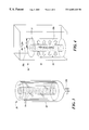
- FIG. 4 illustrates the raw preform of FIG. 3 placed within an oven to be heated to a selected temperature for a selected time duration to cause the diffusion of the dopant material to form a finished preform
- FIG. 5 illustrates a plurality of curves that schematically depict the diffusion of the dopant material as the heating of the preform progresses
- FIG. 6 schematically illustrates drawing an optical fiber from the finished preform
- FIG. 7A schematically illustrates the phenomenon of modal dispersion in an optical fiber having a uniform index of refraction
- FIG. 7B schematically illustrates that an optical fiber formed according to the teachings of the present invention ameliorates the modal dispersion when the fiber is employed to transmit data in a multi-mode fashion.
- the present invention provides a method for producing an optical fiber with a graded index of refraction that varies continuously in a selected direction.
- the optical fiber is formed of an amorphous fluoropolymer to render the fiber transparent to radiation over a wide range of the electromagnetic spectrum, e.g., in a range from ultraviolet to infrared.
- a dopant material, introduced into the fluoropolymer with a graded distribution, as discussed below, provides the fiber with a graded refractive index.
- the graded refractive index advantageously substantially eliminates modal dispersion in a multi-mode operation of the fiber, thus providing the fiber with a large bandwidth for transmission of data at a high rate.
- a fiber formed according to the invention can be employed to transmit data at a rate of a few Gigabits per seconds.
- FIG. 1 illustrates a flowchart 10 depicting the various steps of forming a graded-refractive index optical fiber in accord with a preferred method of the present invention.
- a tube formed of an amorphous fluoropolymer preferably selected to be a copolymer of polytetrafluroroethylene and 2,2-bis(trifuoromethyl)-4,5-difluoro-1,3-dioxol with a selected melting temperature, having a particular index of refraction is provided.
- the tube has a longitudinal axis and a radial axis, and is selected to have a bore extending along its longitudinal axis.
- the bore is filled with a liquid dopant material having an index of refraction that is different, for example larger, than the index of refraction of the tube, to form a raw preform.
- the dopant material for example, can be selected to be an oligomer of trifluorchloroethylene.
- the raw preform is heated for a sufficient duration to cause diffusion of the dopant material in the direction of the radial axis of the raw preform, to form a finished preform having a graded-refractive index in the radial direction.
- the finished preform is drawn to create an optical fiber having the graded-refractive index.
- an illustrative tube 20 to be utilized in the method of the invention is formed of an amorphous fluoropolymer, selected to be substantially free of C—H bonds.
- a copolymer of PTFE and 2,2-bis(trifuoromethyl)-4,5-difluoro-1,3-dioxol can be employed to form the tube 20 .
- Polymeric materials typically include C—H bonds which exhibit vibrational and deformation bands in the near infrared region of the electromagnetic spectrum, and hence cause absorption loss in this region.
- selecting the amorphous fluoropolymer for forming the tube 20 to be substantially free of free C—H bonds advantageously reduces the absorption coefficient of the tube 20 in the infrared region of the electromagnetic spectrum, for example in the wavelength range from 600 to 1550 nm.
- the lower absorption coefficient in turn enhances the transparency of an optical fiber to be made from the tube 20 , as described below, in such a wavelength region.
- employing an amorphous fluoropolymer in the present invention rather than a crystalline fluororesin advantageously eliminates light scattering from various crystalline domains of a crystalline resin, to further enhance the transparency of an optical fiber to be formed according to the method of the invention.
- the illustrated tube 20 has a longitudinal axis L and a radial axis R, and further includes a bore 22 that extends along the longitudinal axis L.
- the diameter of the bore 22 is preferably selected to be a few millimeters, e.g., one to two millimeters.
- the selection of the diameter of bore 22 depends on a number of factors including the diameter of tube 20 , the desired core size of the optical fiber to be formed, the transport properties of the dopant material, and can be approximately determined based on the modeling of the diffusion process.
- the illustrated bore 22 has two openings 22 a and 22 b at its two ends which provide access to the space within the bore 22 .
- the illustrated tube 20 has a circular cross-section, those skilled in the art will understand that it is possible to choose other shapes, such as triangular or polygonal, for the cross-section of the tube 20 .
- the bore 22 can be configured to have only one opening to the external environment rather than the two illustrated openings 22 a and 22 b.
- tube 20 can be formed by injection molding, casting, and spin casting.
- a powder of a selected fluoropolymer such those available from Dupont Company of Delaware, U.S.A under the trade designations Teflon AF1600 or Teflon AF 2400, is fed into the extruder machine and is extruded to form the tube 20 .
- the bore 22 of tube 20 is filled with a liquid dopant material 24 that has a refractive index that is selected to be different from that of the fluoropolymer forming tube 20 .
- a liquid dopant material 24 that has a refractive index that is selected to be different from that of the fluoropolymer forming tube 20 .
- a jacket 28 such as a plastic jacket, clamped at one end by a clamp 28 a provides an enclosure for preform 26 and closes end 22 b , to allow filling the bore 22 with the liquid dopant 24 .
- the bore 22 has only one opening, rather than two, to allow filling the bore with a liquid dopant without a need for a jacket.
- the dopant material 24 is selected to be substantially free of C—H bonds to provide enhanced transparency in the infrared region of the electromagnetic spectrum.
- One preferred embodiment of the invention employs an oligomer of trifluorochloroethylene as the liquid dopant material 24 . The presence of chlorine atoms in this dopant material results in an index of refraction that is greater than that of the fluoropolymer forming the tube 20 .
- Employing a liquid dopant material has a number of advantages over conventional techniques which insert a rod having a dopant material distributed therein in the bore of a tube, such as the tube 20 , and heating the assembly to create a graded distribution of the dopant material.
- employing a liquid dopant obviates the need for producing the bore 22 with precise dimensions so that the rod would fit therein, thereby lowering the manufacturing time and cost.
- employing a liquid dopant material allows utilizing pure dopant material with a concomitant increase of the concentration of the dopant material in the bore 22 .
- Employing a rod may cause defects at the boundary between the rod and the tube upon heat fusion of the rod with the tube. Such defects are less likely to develop when a liquid dopant material is employed.
- employing a pure dopant material improves the reproducibility of the refractive gradient among different batches of optical fibers produced in accordance with the method of the present invention.
- FIG. 4 illustrates the heating step.
- the raw preform 26 is placed in an oven 30 , such as a vacuum heated oven, and is heated at a selected temperature for a sufficient duration to cause diffusion of the dopant material in the direction of the radial axis R of the tube 20 , and diffusion of the fluoropolymer material of the tube 20 into bore 22 . This fuses the bore, thereby producing a finished preform.
- an oven 30 such as a vacuum heated oven
- the raw preform 26 is preferably maintained at a temperature of approximately 30° C. above the glass transition temperature of the polymer for a sufficient duration, in the range of approximately 200 to 500 hours, to form the finished preform.
- C(r,t) denotes the concentration of the dopant material at a position r from a central axis 26 a of the preform 26 at a time t after the initiation of the heating of the raw preform 26
- D is the diffusion constant which, among other factors, depends on the temperature at which the preform is maintained and the physical properties of the diffusing material.
- the diffusion coefficient can be approximated to be a constant when the diffusion process occurs above the glass transition of the polymer.
- Equation (2) indicates that the dopant material is confined at all times within the preform 26 ; that is, the rate of flow of the dopant material through the outer boundary 26 b of the preform 26 is zero.
- Equation (3) is based on the assumption that the dopant material is initially distributed uniformly within the bore 22 of the tube 20 .
- boundary Equation (4) indicates that initially, no dopant material is present within the annular space of the tube 20 , i.e., the space beyond bore 22 .
- C(t,r) denotes the concentration of the dopant material at a position r from central axis 26 a
- C 0 represents the initial concentration of the dopant material
- J 0 and J 1 are zeroth order and first order Bessel functions, respectively
- R 1 is the radius of bore 22
- R 2 is the radius of tube 20
- ⁇ n represents the roots of the zeroth order Bessel function J 0 ( ⁇ n )
- D is the diffusion coefficient
- Equation (4) indicates that as time passes, the dopant material 24 diffuses into the annular portion of the tube 20 .
- This diffusion process can be better understood by reference to FIG. 5, which illustrates a graph 34 that includes curves 36 a , 36 b , 36 c , and 36 d , which schematically illustrate the distribution of the dopant material within preform 26 at different time intervals during heating of preform 26 .
- curve 36 a illustrates that initially, i.e., before heating the raw preform 26 , all the dopant material is confined within bore 22 with a uniform distribution.
- Curves 36 b , 36 c , and 36 d which are approximately Gaussian and have progressively wider widths, schematically illustrate the distribution of the dopant material upon heating the preform as a function of time. As time passes, the distribution of the dopant material flattens out, with more of the dopant material penetrating into the annular portion of tube 20 .
- the actual distribution of the dopant material may be different that those depicted in FIG. 5 . Further, those skilled in the art will appreciate that while the dopant material is diffusing into the annular portion of tube 20 , there is also a diffusion of the fluoropolymer into the filled bore 22 which, over time, results in fusion of bore 22 .
- heating the raw preform 26 causes a flux of the dopant material 32 into the annular portion of tube 20 , and further causes a flux of the fluoropolymer forming tube 20 into bore 22 , to fuse bore 22 and form a graded distribution of the dopant material within the preform 26 .
- the dopant material 32 is selected to have a refractive index that is different from that of the fluoropolymer forming tube 22 , a graded distribution of the dopant material leads to a graded distribution of the refractive index in the finished preform.
- the finished preform is drawn to form an optical fiber having a graded refractive index similar to that of the finished preform.
- FIG. 6 schematically depicts the process of drawing the finished preform to form an optical fiber.
- a heater 38 heats a finished preform 40 , as it is fed into the space within the heater 38 , to a temperature that is selected to be preferably above the glass transition temperature of the finished preform 40 .
- Fiber 42 is drawn from the preform 40 .
- a spool 44 collects the optical fiber 42 .
- the drawn optical fiber 42 has substantially the same graded distribution of the dopant material, and hence substantially the same graded index of refraction as that of the finished preform.
- FIG. 7A schematically illustrates an optical fiber 46 having a uniform index of refraction.
- Two pulses of light 48 and 50 separated by a time interval T 1 , and injected at different angles into the optical fiber 46 at one end 46 a thereof, traverse different path lengths through the optical fiber 46 before exiting through an opposed end 46 b of the fiber 46 .
- the differential in the path lengths traversed by the two beams 48 and 50 causes the time separation of the exiting pulses 48 a and 50 a to be less than the time separation of the pulses 48 and 50 .
- the exiting pulses 48 a and 50 a are partially overlapping.
- Such a modal dispersion in an optical fiber having a uniform index of refraction results in a low bandwidth, thereby limiting the rate of data transmission through the fiber.
- FIG. 7B shows the two light pulses 48 and 50 , separated by a time interval T 1 , are injected at different angles into an optical fiber 52 produced according to the present invention to have a graded refractive index.
- the light pulses 48 and 50 sample different portions of the fiber 52 , having different indices of refraction, as they traverse through the fiber 52 .
- the two light pulses 48 and 50 may traverse different physical pathlengths, they have substantially similar optical pathlengths as they traverse through the fiber 52 .
- a time separation T 2 of the exiting pulses 48 a and 50 a is substantially similar to the time separation T 1 of the entry pulses 48 and 50 .
- the substantial elimination of the modal dispersion advantageously allows transmitting optical information through the optical fiber of the invention in a multi-mode fashion at rates that are substantially faster than those achieved in conventional fibers.
- an optical fiber produced according to the present invention can be employed to transmit data at a rate of a few Gigabits per second.
- an optical fiber formed according to the method of the invention is chemically stable and is transparent to radiation ranging from ultraviolet to infrared.
- An optical fiber of the invention can be employed in a variety of applications. For example, such an optical fiber can be installed in a residential or office building to carry data among a variety of instruments and/or appliances. Further, an optical fiber of the invention can be installed in an automobile for transmission of signals to various systems of the automobile.
Landscapes
- Engineering & Computer Science (AREA)
- Health & Medical Sciences (AREA)
- Manufacturing & Machinery (AREA)
- Ophthalmology & Optometry (AREA)
- Mechanical Engineering (AREA)
- Optical Fibers, Optical Fiber Cores, And Optical Fiber Bundles (AREA)
Abstract
Description


Claims (16)
Priority Applications (3)
| Application Number | Priority Date | Filing Date | Title |
|---|---|---|---|
| US09/461,482 US6602448B1 (en) | 1999-12-14 | 1999-12-14 | Graded plastic optical element and method for producing thereof |
| AU25796/01A AU2579601A (en) | 1999-12-14 | 2000-12-14 | Graded plastic optical element and method for producing thereof |
| PCT/US2000/033948 WO2001043954A1 (en) | 1999-12-14 | 2000-12-14 | Graded plastic optical element and method for producing thereof |
Applications Claiming Priority (1)
| Application Number | Priority Date | Filing Date | Title |
|---|---|---|---|
| US09/461,482 US6602448B1 (en) | 1999-12-14 | 1999-12-14 | Graded plastic optical element and method for producing thereof |
Publications (1)
| Publication Number | Publication Date |
|---|---|
| US6602448B1 true US6602448B1 (en) | 2003-08-05 |
Family
ID=23832738
Family Applications (1)
| Application Number | Title | Priority Date | Filing Date |
|---|---|---|---|
| US09/461,482 Expired - Lifetime US6602448B1 (en) | 1999-12-14 | 1999-12-14 | Graded plastic optical element and method for producing thereof |
Country Status (3)
| Country | Link |
|---|---|
| US (1) | US6602448B1 (en) |
| AU (1) | AU2579601A (en) |
| WO (1) | WO2001043954A1 (en) |
Cited By (3)
| Publication number | Priority date | Publication date | Assignee | Title |
|---|---|---|---|---|
| WO2005090450A1 (en) * | 2004-03-17 | 2005-09-29 | The University Of Sydney | Solution doping of polymer optical fibres |
| US20120255863A1 (en) * | 2011-04-05 | 2012-10-11 | Joye Colin D | Microfabrication of Tunnels |
| USD901664S1 (en) * | 2016-10-28 | 2020-11-10 | Energizer Brands II, LLC | Air freshener |
Citations (8)
| Publication number | Priority date | Publication date | Assignee | Title |
|---|---|---|---|---|
| US3718383A (en) * | 1971-04-19 | 1973-02-27 | Eastman Kodak Co | Plastic optical element having refractive index gradient |
| US5253323A (en) | 1990-08-16 | 1993-10-12 | Yasuhiro Koike | Method of manufacturing a graded optical transmission medium made of synthetic resin |
| EP0615141A1 (en) | 1992-08-17 | 1994-09-14 | KOIKE, Yasuhiro | Method of manufacturing plastic light transmitters |
| EP0710855A1 (en) | 1994-04-18 | 1996-05-08 | Yasuhiro Koike | Refractive index distribution type optical resin and production method thereof |
| US5541247A (en) | 1991-10-22 | 1996-07-30 | Koike; Yasuhiro | Optical resin materials with distributed refractive index, process for producing the materials, and optical conductors using the materials |
| US5760139A (en) | 1994-04-18 | 1998-06-02 | Yasuhiro Koike | Graded-refractive-index optical plastic material and method for its production |
| US5916971A (en) | 1995-06-09 | 1999-06-29 | Yasuhiro Koike | Graded-refractive-index optical plastic material and method for its production |
| US6086999A (en) * | 1997-06-12 | 2000-07-11 | Boston Optical Fiber, Inc. | Method for producing a graded index plastic optical material |
-
1999
- 1999-12-14 US US09/461,482 patent/US6602448B1/en not_active Expired - Lifetime
-
2000
- 2000-12-14 WO PCT/US2000/033948 patent/WO2001043954A1/en not_active Ceased
- 2000-12-14 AU AU25796/01A patent/AU2579601A/en not_active Abandoned
Patent Citations (12)
| Publication number | Priority date | Publication date | Assignee | Title |
|---|---|---|---|---|
| US3718383A (en) * | 1971-04-19 | 1973-02-27 | Eastman Kodak Co | Plastic optical element having refractive index gradient |
| US5253323A (en) | 1990-08-16 | 1993-10-12 | Yasuhiro Koike | Method of manufacturing a graded optical transmission medium made of synthetic resin |
| US5541247A (en) | 1991-10-22 | 1996-07-30 | Koike; Yasuhiro | Optical resin materials with distributed refractive index, process for producing the materials, and optical conductors using the materials |
| US5763514A (en) | 1991-10-22 | 1998-06-09 | Koike; Yasuhiro | Process for producting optical resin materials with distributed refractive index |
| US5767200A (en) | 1991-10-22 | 1998-06-16 | Koike; Yasuhiro | Optical resin materials with distributed refractive index |
| EP0615141A1 (en) | 1992-08-17 | 1994-09-14 | KOIKE, Yasuhiro | Method of manufacturing plastic light transmitters |
| US5593621A (en) | 1992-08-17 | 1997-01-14 | Koike; Yasuhiro | Method of manufacturing plastic optical transmission medium |
| EP0710855A1 (en) | 1994-04-18 | 1996-05-08 | Yasuhiro Koike | Refractive index distribution type optical resin and production method thereof |
| US5760139A (en) | 1994-04-18 | 1998-06-02 | Yasuhiro Koike | Graded-refractive-index optical plastic material and method for its production |
| US5783636A (en) | 1994-04-18 | 1998-07-21 | Yasuhiro Koike | Graded-refractive-index optical plastic material and method for its production |
| US5916971A (en) | 1995-06-09 | 1999-06-29 | Yasuhiro Koike | Graded-refractive-index optical plastic material and method for its production |
| US6086999A (en) * | 1997-06-12 | 2000-07-11 | Boston Optical Fiber, Inc. | Method for producing a graded index plastic optical material |
Cited By (5)
| Publication number | Priority date | Publication date | Assignee | Title |
|---|---|---|---|---|
| WO2005090450A1 (en) * | 2004-03-17 | 2005-09-29 | The University Of Sydney | Solution doping of polymer optical fibres |
| US20120255863A1 (en) * | 2011-04-05 | 2012-10-11 | Joye Colin D | Microfabrication of Tunnels |
| US9777384B2 (en) * | 2011-04-05 | 2017-10-03 | The United States Of America, As Represented By The Secretary Of The Navy | Microfabrication of tunnels |
| US20180030606A1 (en) * | 2011-04-05 | 2018-02-01 | The Government Of The United States Of America, As Represented By The Secretary Of The Navy | Microfabrication of Tunnels |
| USD901664S1 (en) * | 2016-10-28 | 2020-11-10 | Energizer Brands II, LLC | Air freshener |
Also Published As
| Publication number | Publication date |
|---|---|
| WO2001043954A1 (en) | 2001-06-21 |
| AU2579601A (en) | 2001-06-25 |
| WO2001043954A9 (en) | 2002-07-11 |
Similar Documents
| Publication | Publication Date | Title |
|---|---|---|
| EP1297368B1 (en) | Method of manufacturing a plastic photonic crystal fiber for terahertz wave transmission | |
| US7058271B2 (en) | Plastic optical fiber | |
| US7062140B2 (en) | Composite material photonic crystal fibres, method of production and its use | |
| EP1494847B1 (en) | Process for manufacturing a micro-structured optical fibre | |
| US20030190130A1 (en) | Multiple optical pathway fiber optic cable | |
| US7135133B2 (en) | Method and apparatus for manufacturing plastic optical transmission medium | |
| US6602448B1 (en) | Graded plastic optical element and method for producing thereof | |
| EP1395861A1 (en) | Method of optical fibre preform manufacture | |
| WO2004046777A1 (en) | Microstructured polymer signal guiding element | |
| US6265018B1 (en) | Fabricating graded index plastic optical fibers | |
| Asai et al. | High-bandwidth graded-index plastic optical fiber by the dopant diffusion coextrusion process | |
| JP2003322729A (en) | Optical fiber and method for manufacturing the same | |
| JP2004177954A (en) | Plastic optical fiber preform | |
| US7305166B1 (en) | Graded refractive index optical fibers, optical components fabricated to include plural graded index optical fibers and methods of fabricating the same | |
| US20120063734A1 (en) | Multimode graded-index plastic optical fiber and method for producing the same | |
| KR100384440B1 (en) | Method of fabricating polymeric fiber having radially-varying properties and apparatus therefor | |
| US20030091306A1 (en) | Rod type polymer preform having radially-varying properties, process for the preparation thereof and apparatus therefor | |
| JP4071135B2 (en) | Fiber optic and liquid sensors | |
| Veit | Optical Fibers | |
| Asai et al. | Control of Refractive Index Distribution for High-Bandwidth Graded Index PlasticOptical Fiber | |
| JPH04295807A (en) | Multi-core plastic waveguide | |
| JP2001033603A (en) | How to make optical components | |
| AU2002308422A1 (en) | Method of optical fibre preform manufacture |
Legal Events
| Date | Code | Title | Description |
|---|---|---|---|
| AS | Assignment |
Owner name: WANG LABORATORIES INC. (PREDECESSOR IN INTEREST TO Free format text: SECURITY AGREEMENT;ASSIGNOR:BOSTON OPTICAL FIBER, INC.;REEL/FRAME:010615/0229 Effective date: 19960422 |
|
| AS | Assignment |
Owner name: BOSTON OPTICAL FIBER, INC., MASSACHUSETTS Free format text: ASSIGNMENT OF ASSIGNORS INTEREST;ASSIGNOR:ILYASHENKO, VICTOR;REEL/FRAME:010838/0329 Effective date: 20000508 |
|
| FEPP | Fee payment procedure |
Free format text: PAYOR NUMBER ASSIGNED (ORIGINAL EVENT CODE: ASPN); ENTITY STATUS OF PATENT OWNER: LARGE ENTITY |
|
| AS | Assignment |
Owner name: GETRONICSWANG CO., LLC, MASSACHUSETTS Free format text: CONFIRMATORY ASSIGNMENT;ASSIGNOR:BOSTON OPTICAL FIBER INC.;REEL/FRAME:014135/0423 Effective date: 20000524 |
|
| STCF | Information on status: patent grant |
Free format text: PATENTED CASE |
|
| FPAY | Fee payment |
Year of fee payment: 4 |
|
| AS | Assignment |
Owner name: BEAR STEARNS CORPORATE LENDING, INC., TEXAS Free format text: SECURITY AGREEMENT;ASSIGNOR:GETRONICS USA INC.;REEL/FRAME:021450/0001 Effective date: 20080820 |
|
| AS | Assignment |
Owner name: GETRONICS USA, INC., TEXAS Free format text: CHANGE OF NAME;ASSIGNOR:GETRONICSWANG CO., LLC;REEL/FRAME:023607/0971 Effective date: 20060829 Owner name: COMPUCOM SYSTEMS, INC., TEXAS Free format text: MERGER;ASSIGNOR:GETRONICS USA, INC.;REEL/FRAME:023607/0975 Effective date: 20081224 |
|
| REMI | Maintenance fee reminder mailed | ||
| FPAY | Fee payment |
Year of fee payment: 8 |
|
| SULP | Surcharge for late payment |
Year of fee payment: 7 |
|
| AS | Assignment |
Owner name: COMPUCOM SYSTEMS, INC., AS SUCCESSOR-IN-INTEREST T Free format text: RELEASE OF SECURITY INTEREST IN PATENT COLLATERAL AT REEL/FRAME NO. 21450/0001;ASSIGNOR:BEAR STEARNS CORPORATE LENDING INC.;REEL/FRAME:029074/0759 Effective date: 20121004 |
|
| AS | Assignment |
Owner name: CITIBANK, N.A., AS ADMINISTRATIVE AGENT, DELAWARE Free format text: GRANT OF SECURITY INTEREST IN UNITED STATES PATENTS;ASSIGNOR:COMPUCOM SYSTEMS, INC.;REEL/FRAME:030389/0533 Effective date: 20130509 |
|
| FEPP | Fee payment procedure |
Free format text: PAYER NUMBER DE-ASSIGNED (ORIGINAL EVENT CODE: RMPN); ENTITY STATUS OF PATENT OWNER: LARGE ENTITY |
|
| FEPP | Fee payment procedure |
Free format text: PAYOR NUMBER ASSIGNED (ORIGINAL EVENT CODE: ASPN); ENTITY STATUS OF PATENT OWNER: LARGE ENTITY |
|
| FPAY | Fee payment |
Year of fee payment: 12 |
|
| AS | Assignment |
Owner name: COMPUCOM SYSTEMS, INC., TEXAS Free format text: RELEASE BY SECURED PARTY;ASSIGNOR:CITIBANK, N.A.;REEL/FRAME:044075/0204 Effective date: 20171108 Owner name: GOLDMAN SACHS LENDING PARTNERS LLC, AS COLLATERAL Free format text: SECURITY AGREEMENT;ASSIGNORS:COMPUCOM SYSTEMS, INC.;OFFICE DEPOT, INC.;OMX, INC.;REEL/FRAME:044700/0965 Effective date: 20171108 |
|
| AS | Assignment |
Owner name: JPMORGAN CHASE BANK, N.A., ILLINOIS Free format text: PATENT SECURITY AGREEMENT;ASSIGNOR:COMPUCOM SYSTEMS, INC.;REEL/FRAME:044799/0307 Effective date: 20171108 |
|
| AS | Assignment |
Owner name: LINCOLN MERGER SUB TWO, LLC, FLORIDA Free format text: RELEASE BY SECURED PARTY;ASSIGNOR:GOLDMAN SACHS LENDING PARTNERS LLC;REEL/FRAME:052437/0762 Effective date: 20200417 Owner name: SOLUTIONS4SURE.COM, INC., FLORIDA Free format text: RELEASE BY SECURED PARTY;ASSIGNOR:GOLDMAN SACHS LENDING PARTNERS LLC;REEL/FRAME:052437/0762 Effective date: 20200417 Owner name: CSI FUNDING INC., TEXAS Free format text: RELEASE BY SECURED PARTY;ASSIGNOR:GOLDMAN SACHS LENDING PARTNERS LLC;REEL/FRAME:052437/0762 Effective date: 20200417 Owner name: OFFICE DEPOT FOREIGN HOLDINGS GP, LLC, FLORIDA Free format text: RELEASE BY SECURED PARTY;ASSIGNOR:GOLDMAN SACHS LENDING PARTNERS LLC;REEL/FRAME:052437/0762 Effective date: 20200417 Owner name: OFFICE DEPOT FOREIGN HOLDINGS LP, LLC, FLORIDA Free format text: RELEASE BY SECURED PARTY;ASSIGNOR:GOLDMAN SACHS LENDING PARTNERS LLC;REEL/FRAME:052437/0762 Effective date: 20200417 Owner name: EDEPOT, LLC, CALIFORNIA Free format text: RELEASE BY SECURED PARTY;ASSIGNOR:GOLDMAN SACHS LENDING PARTNERS LLC;REEL/FRAME:052437/0762 Effective date: 20200417 Owner name: MAPLEBY HOLDINGS MERGER CORPORATION, FLORIDA Free format text: RELEASE BY SECURED PARTY;ASSIGNOR:GOLDMAN SACHS LENDING PARTNERS LLC;REEL/FRAME:052437/0762 Effective date: 20200417 Owner name: PICABO HOLDINGS, INC., FLORIDA Free format text: RELEASE BY SECURED PARTY;ASSIGNOR:GOLDMAN SACHS LENDING PARTNERS LLC;REEL/FRAME:052437/0762 Effective date: 20200417 Owner name: BIZMART, INC., FLORIDA Free format text: RELEASE BY SECURED PARTY;ASSIGNOR:GOLDMAN SACHS LENDING PARTNERS LLC;REEL/FRAME:052437/0762 Effective date: 20200417 Owner name: COMPUCOM SYSTEMS FEDERAL, INC., TEXAS Free format text: RELEASE BY SECURED PARTY;ASSIGNOR:GOLDMAN SACHS LENDING PARTNERS LLC;REEL/FRAME:052437/0762 Effective date: 20200417 Owner name: OFFICE DEPOT, INC., FLORIDA Free format text: RELEASE BY SECURED PARTY;ASSIGNOR:GOLDMAN SACHS LENDING PARTNERS LLC;REEL/FRAME:052437/0762 Effective date: 20200417 Owner name: OMX, INC., FLORIDA Free format text: RELEASE BY SECURED PARTY;ASSIGNOR:GOLDMAN SACHS LENDING PARTNERS LLC;REEL/FRAME:052437/0762 Effective date: 20200417 Owner name: BIZMART (TEXAS), INC., FLORIDA Free format text: RELEASE BY SECURED PARTY;ASSIGNOR:GOLDMAN SACHS LENDING PARTNERS LLC;REEL/FRAME:052437/0762 Effective date: 20200417 Owner name: MINIDOKA PAPER COMPANY, FLORIDA Free format text: RELEASE BY SECURED PARTY;ASSIGNOR:GOLDMAN SACHS LENDING PARTNERS LLC;REEL/FRAME:052437/0762 Effective date: 20200417 Owner name: COMPUCOM FINANCE, INC., TEXAS Free format text: RELEASE BY SECURED PARTY;ASSIGNOR:GOLDMAN SACHS LENDING PARTNERS LLC;REEL/FRAME:052437/0762 Effective date: 20200417 Owner name: OFFICEMAX CORP., FLORIDA Free format text: RELEASE BY SECURED PARTY;ASSIGNOR:GOLDMAN SACHS LENDING PARTNERS LLC;REEL/FRAME:052437/0762 Effective date: 20200417 Owner name: OFFICEMAX SOUTHERN COMPANY, FLORIDA Free format text: RELEASE BY SECURED PARTY;ASSIGNOR:GOLDMAN SACHS LENDING PARTNERS LLC;REEL/FRAME:052437/0762 Effective date: 20200417 Owner name: COMPUCOM PUERTO RICO, LLC, TEXAS Free format text: RELEASE BY SECURED PARTY;ASSIGNOR:GOLDMAN SACHS LENDING PARTNERS LLC;REEL/FRAME:052437/0762 Effective date: 20200417 Owner name: COMPUCOM SYSTEMS, INC., TEXAS Free format text: RELEASE BY SECURED PARTY;ASSIGNOR:GOLDMAN SACHS LENDING PARTNERS LLC;REEL/FRAME:052437/0762 Effective date: 20200417 Owner name: COMPUCOM INTERMEDIATE HOLDINGS INC., TEXAS Free format text: RELEASE BY SECURED PARTY;ASSIGNOR:GOLDMAN SACHS LENDING PARTNERS LLC;REEL/FRAME:052437/0762 Effective date: 20200417 Owner name: VIKING OFFICE PRODUCTS, INC., FLORIDA Free format text: RELEASE BY SECURED PARTY;ASSIGNOR:GOLDMAN SACHS LENDING PARTNERS LLC;REEL/FRAME:052437/0762 Effective date: 20200417 Owner name: 4SURE.COM, INC., FLORIDA Free format text: RELEASE BY SECURED PARTY;ASSIGNOR:GOLDMAN SACHS LENDING PARTNERS LLC;REEL/FRAME:052437/0762 Effective date: 20200417 Owner name: LNS TECHNOLOGIES, INC., TEXAS Free format text: RELEASE BY SECURED PARTY;ASSIGNOR:GOLDMAN SACHS LENDING PARTNERS LLC;REEL/FRAME:052437/0762 Effective date: 20200417 Owner name: OFFICEMAX INCORPORATED, FLORIDA Free format text: RELEASE BY SECURED PARTY;ASSIGNOR:GOLDMAN SACHS LENDING PARTNERS LLC;REEL/FRAME:052437/0762 Effective date: 20200417 Owner name: THE OFFICE CLUB, INC., FLORIDA Free format text: RELEASE BY SECURED PARTY;ASSIGNOR:GOLDMAN SACHS LENDING PARTNERS LLC;REEL/FRAME:052437/0762 Effective date: 20200417 Owner name: COMPUCOM SUPER HOLDINGS LLC, TEXAS Free format text: RELEASE BY SECURED PARTY;ASSIGNOR:GOLDMAN SACHS LENDING PARTNERS LLC;REEL/FRAME:052437/0762 Effective date: 20200417 Owner name: OFFICEMAX NORTH AMERICA, INC., FLORIDA Free format text: RELEASE BY SECURED PARTY;ASSIGNOR:GOLDMAN SACHS LENDING PARTNERS LLC;REEL/FRAME:052437/0762 Effective date: 20200417 Owner name: OD INTERNATIONAL, INC., FLORIDA Free format text: RELEASE BY SECURED PARTY;ASSIGNOR:GOLDMAN SACHS LENDING PARTNERS LLC;REEL/FRAME:052437/0762 Effective date: 20200417 |
|
| AS | Assignment |
Owner name: COMPUCOM SYSTEMS, INC., TEXAS Free format text: RELEASE OF SECURITY INTEREST IN PATENTS PREVIOUSLY RECORDED AT REEL/FRAME (044799/0307);ASSIGNOR:JPMORGAN CHASE BANK, N.A., AS ADMINISTRATIVE AGENT;REEL/FRAME:058602/0683 Effective date: 20211231 |