This application is a U.S. National Phase Application of PCT International Application PCT/JP00/04161.
TECHNICAL FIELD
The present invention relates to a robot machine and particularly relates to an origin point adjustment method thereof.
BACKGROUND ART
The instructing process of a prior art teaching playback type robot is performed while the robot being actually operated. Because of such an instructing method as above, a lot of teaching playback type robots have been widely used in the industry and the market thereof is still expanding. The operating accuracy of a teaching playback type robot is positional accuracy in reproducibility of a teaching point. Therefore, the individuality of each respective robot and absolute positional accuracy have not been considered important. The foregoing tendency is still prevailing.
In recent years, however, a demand for a reduction in teaching steps of teaching playback type robots has been growing and there are great expectations upon an off-line teaching process that allows the teaching process and performance simulation of robots to be taken place on a display with the use of a computer. By living up to the expectations, many off-line teaching systems have been introduced to the market and actually in use.
However, the positional difference existing between the structural model of a robot defined inside a computer and the actual robot in use becomes a serious cause of degrading the teaching accuracy involved. Therefore, it is necessary at present for a teaching program prepared by the use of an off-line teaching system to be corrected at worksite and actually many corrective teaching instructions are provided.
In addition to the positional accuracy, a high degree of accuracy has been required of an operating path when a CP(continuous path) operation is taking place.
In order to satisfy the foregoing requirement, considerable efforts have been put into enhancing the computing speed and accuracy of a robot controller and achieving a higher degree of accuracy in machining the respective mechanical parts that constitute robot arms. However, in the same way as in the case of off-line teaching, the positional difference existing between the structural model of a robot defined inside a robot controller and the actual robot has a great effect on the accuracy of an operating path. Therefore, market requirements with respect to operating path accuracy at the time of CP operation are not allowed to be satisfied sufficiently.
The positional difference between the structural model of a robot and an actual robot causes adverse effects on individuality, absolute positional accuracy and operating path accuracy of the robot.
The foregoing positional difference is caused by machining accuracy of arm length, twisting between axes and the like, assembly accuracy and shifting in position of the original point of rotational joint axis. Above all, the shifting in position of the original point of rotational joint axis has the greatest influence to cause the positional difference.
As the method of calibration is considered a method for applying a correction to a structural model by taking measurements of a positional difference between the structural model of a robot and an actual robot. This calibration method is being studied for calibration purposes of robots. A few different methods are proposed as the calibration method. However, since the measurement of the positional difference needs to be performed with an extremely high degree of accuracy, the method of measurement itself is difficult and requires very expensive measurement instruments. As a result, the method of applying calibration to a structural model has not so far prevailed in the industry. Therefore, the inventor of the present invention proposed a method of using a tilt angle sensor in the Japanese Patent Application Unexamined Publication No. H05-318351 as the method for facilitating automated measurement at a relatively low cost.
Next, a brief description is given to a prior art method with reference to FIG. 1, FIG. 7 and FIG. 8. Particularly, FIG. 1 is used for guidance in order to make the description simple.
FIG. 1 is a perspective view of an example of the robots that are targeted for an origin point adjustment. Robot 1 in FIG. 1 comprises six rotational joint axes of first joint axis J1 to six joint axis J6. As FIG. 1 shows, respective joint axes J1 to J6 are allowed to be moved in rotational directions a to f by controller 2 that controls the motion of the robot.
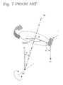
FIG. 7 is a conceptual illustration of an original point adjustment method as employed in a prior art robot and shows in a schematic form third joint axis J3, fourth joint axis J4 and tilt angle sensor 3 mounted on the tip of robot arm for the robot as shown in FIG. 1, for example. As FIG. 7 shows, fourth joint axis J4 is tilting by angle α from direction G of gravity due to the rotation of third joint axis J3 that makes the center axis of rotation for fourth joint axis J4. Tilt angle sensor 3 is mounted on the tip of robot arm via fifth joint axis J5 and six joint axis J6. (Refer to FIG. 1.)
In the foregoing, the sensor mounting surface serving as a reference surface of detection for tilt angle sensor 3 is assumed to make a tilting angle of γ (not shown in FIG. 1) against fourth joint axis J4.
In addition, an encoder (not shown in FIG. 1) acting as means for measuring a rotational angle of joint axis is attached to each respective rotational joint axis.
With a robot that is structured as described in above, while fourth joint axis J4 being rotated by controller 2 (refer to FIG. 1), tilt angle γ and rotational angle Θ of joint axis are measured at predetermined rotational angle positions by tilt angle sensor 3 and the encoder, respectively.
FIG. 8 shows the relationship between rotational angle Θ of fourth joint axis J4 (the same Θ as shown in FIG. 7) and tilt angleY measured according to the original point adjustment method as described in above. In FIG. 8, the maximum value of tilt angleY is Ymax, the minimum value is Ymin and, when tilt angleY equals to the mean value of the maximum and minimum values thereof, a rotational angle of fourth joint axis J4 is defined as Θzero.
As is evident from FIG. 7 and FIG. 8, tilt angle α of fourth joint axis J4 against direction G of gravity can be derived by calculation in such a way as dividing the difference between the maximum valueYmax and minimum valueYmin of the measured tilt angleY by two. Further, the direction of tilt is allowed to be measured with reference to Θzero.
Thus, the original point position of third joint axis J3 can be readily adjusted by the use of a value of tilt angle α of the rotational center of fourth joint axis J4 measured and derived by calculation as described in above. The foregoing adjustment method can be applied to other axes equally well.
As described in above, according to the prior art original point adjustment method, tilt angle α of a rotational joint axis against direction G of gravity can be derived from the difference between the maximum and minimum values of tilt angleY. On the other hand, since tilt angle α is not affected by mounting angle γ of tilt angle sensor 3, an adjustment with a high degree of accuracy is made possible without being affected by machining accuracy and the like of the reference surface for mounting the sensor.
In addition, as described in above, mounting angle γ of tilt angle sensor 3 does not have any influence with respect to measurement, thereby allowing the original point position of each respective joint axis to be adjusted in succession as the attitude of robot 1 is being changed as appropriate. Therefore, once a single sensor is attached to the tip of robot arm, adjustments of a plurality of joint axes are made possible by having a rotational angle of each respective joint axis of robot positioned appropriately, thereby allowing even automated adjustment steps to be realized without difficulty.
However, the prior art method has had the following two flaws. Firstly, tilt angle Y and rotational angle Θ are measured continuously and it is needed to find out precisely at what positions of rotational angle tilt angle Y falls on maximum value Ymax and minimum value Ymin. In order to measure the maximum value Ymax and minimum value Ymin of tilt angle Y, it is necessary for rotational angle Θ to be rotated by more than 180° at least. However, when there is not much extra room for the place where a robot is installed, rotational angle Θ is sometimes not allowed to be rotated by more than 180°, thus bringing about the situation where carrying out a measurement itself is difficult.
Secondly, the prior art method has another flaw in that the original point adjustment of an “n”th joint axis is performed by the use of a tilt angle of rotational center axis of an “n+1”th joint axis. As observed with second joint axis J2 of robot in FIG. 1, for example, when parallelism with a rotational joint axis adjoining thereto, i.e., third joint axis J3 is mutually maintained, the prior art method does not allow the adjustment of second joint axis J2 to be performed, thereby requiring the adoption of a different method to carry out the adjustment.
SUMMARY OF THE INVENTION
The present invention deals with the foregoing problems and provides a method of original point adjustment whereby a high accuracy adjustment can be performed even if the room where a robot is allowed to move is limited in space and also an adjustment can be carried out even if joint axes are located in such a way as adjoining rotational joint axes are parallel with one another.
In order to solve the foregoing problems, the present invention proposes with respect to rotational joint axes of a robot machine having a plurality of rotational joint axes, in which adjoining rotational joint axes are not parallel with one another, a method of original point adjustment comprising the steps of:
measuring a rotational angle of rotational joint axis and a tilt angle of robot arm against the direction of gravity at three points or more of rotational angle position at least;
deriving by computation regression factors α and β based on a regression function of Y=α SIN(Θ+β)+γ formed of thus obtained rotational angle information Θi and tilt angle information Yi ; and
performing an original point adjustment based on the obtained tilt angle and tilt direction of rotational joint axis.
BRIEF DESCRIPTION OF DRAWINGS
FIG. 1 is a perspective view of an example of robots that are adjusted in original point according to the present invention and according to prior art methods.
FIG. 2 is a diagram showing the relationship between rotational angle Θi and tilt angleYi measured according to the original point adjustment method of the present invention.
FIG. 3 is a side view of the skeletal model of a robot adjusted in original point according to the present invention, looked from the direction indicated by arrow A in FIG. 1.
FIG. 4 is a diagram of the case where a pivotal motion takes place with the control point of the skeletal model of FIG. 3 fixed to one point.
FIG. 5 is a diagram of the case where second joint axis J2 of FIG. 4 is shifted from an ideal angle by δ.
FIG. 6 is a partially enlarged view of FIG. 5.
FIG. 7 is a conceptual illustration for describing the original point adjustment method of robots according to the present invention and also according to the prior art method.
FIG. 8 is a diagram showing the relationship between rotational angle Θ and tilt angleY measured according to the prior art original point adjustment method for robots.
BEST MODE FOR CARRYING OUT THE INVENTION
Next, a description is given to an exemplary embodiment of the present invention with reference to FIG. 1, FIG. 2 and FIG. 7.
FIG. 1 is a perspective view of one example of robot that is subjected to an original point adjustment, FIG. 2 is a diagram showing the relationship between rotational angle Θi and tilt angle Yi and FIG. 7 is a conceptual illustration for describing an original point adjustment method.
Robot 1 shown in FIG. 1 comprises six rotational joint axes of first joint axis J1 to sixth joint axis J6. With this robot, adjoining second joint axis J2 and third joint axis J3 are parallel with each other in position and other adjoining joint axes are arranged in position perpendicular to one un another.
Respective joint axes J1 to J6 are rotated in respective directions a to f by controller 2 which acts as a control means for the robot.
An encoder (not shown in the drawing) acting as a rotational angle measurement means is attached to each respective joint axis to measure a rotational angle thereof. In addition, each respective joint axis is provided with an original point position (not shown in the drawing) which is used as the reference position of motion for each respective joint axis.
Furthermore, a tilt angle sensor (not shown in the drawing) is attached to the tip of robot arm to measure a tilt angle of the robot arm's tip against the direction of gravity.
In order to have the robot structured as described in above put into motion accurately as intended for according to the program involved, it is necessary for the original point position of each respective rotational axis to be aligned accurately as described in the foregoing.
Next, a description is given to an adjustment method of the original point position of third joint axis J3 by putting fourth joint axis J4 into motion in the same way as in the prior art example.
A conceptual illustration of the relationships existing among third joint axis J3, fourth joint axis J4 and tilt angle sensor 3 that are directly related with the original point adjustment method of the present invention results in FIG. 7.
Further, the surface, on which a tilt angle sensor is mounted, acts as the tilt angle detection reference plane and is assumed to be tilting by angle γ (not shown in the drawing) against fourth joint axis J4.
In order to derive by computation the amount of shifting in the original point position, fourth joint axis J4 is rotated, thereby picking up at least three or more of different rotational angle positions for position setting.
For each respective rotational angle position, tilt angle Yi against the direction of gravity and rotational angle Θi of fourth joint axis J4 are measured, where the subscript i stands for an “i”th measurement datum.
Measured tilt angle Yi and rotational angle Θi are fed into a computation it for deriving original point calibration magnitude (not shown in the drawing), and a tilt angle and a tilt direction for a rotational joint axis in question are derived by computation according to the steps described below.
FIG. 2 is a graph plotting the measured Θi and Yi, where the horizontal axis indicates rotational angle Θ and the vertical axis indicates tilt angle Y. As clearly seen according to the principle involved, the relationship between Θi and Yi is expressed by a SIN function as shown by a broken line in FIG. 2.
Here, a regression function (1) is established as below, thereby deriving regression factors α, β and γ.
Y=α SIN(Θ+β)+γ (1)
Then, the regression function (1) is deformed by linearization to obtain an equation (2).
Y=A SIN(X)+B COS(X)+C (2)
where A, B and C are defined as follows:
A=α COS(β), B=α SIN(β), C=γ (3)
A squared sum E of errors is obtained based on the equation (2) and data Xi and Yi, thereby establishing an equation(4) as follows:
E=Σδi 2=Σ(Yi−C−A SIN(Xi)−B SIN(Xi))2 (4)
By applying partial differential to A, B and C in the equation (4) and making E=0, respectively, equations (5), (6) and (7) are obtained as follows:
0=ΔE/ΔC=ΣYi−nC−Σ SIN(X)A−Σ COS(Xi)B (5)
0=ΔE/ΔA=ΣYi SIN(Xi)−Σ SIN(Xi)C−Σ SIN2(Xi)A−Σ SIN(Xi)COS(Xi)B (6)
0=ΔE/ΔB=ΣYi COS(Xi)−Σ COS(Xi)C−Σ SIN(Xi)COS(Xi)A−ΣCOS2(Xi)B (7)
By applying an arrangement to factors in the equations (5), (6) and (7), a system of simultaneous equations is established as follows:
where respective factors are defined as in the following:
A solution of the system of simultaneous equations (8) is as follows:
Since A, B and C are defined as in the equation (3), what follows is obtained from the equations (10) to (13).
Offset: γ=C
Tilt Direction (Phase): β=TAN−1(B/A) (14)
Tilt Angle (Amplitude): α=A/COS(β)
In FIG. 2, 2α is the amplitude of the SIN function and equals to the difference between maximum value Ymax and minimum value Ymin of tilt angle Y in the prior art example. β becomes the same as tilt direction Θ zero in the prior art example. In the same way as in the prior art example, γ is the mounting angle of tilt sensor 3.
Thus, tilt angle α and tilt direction β of fourth joint axis J4 against direction G of gravity can be obtained.
In addition, according to the original point adjustment method of the present invention, there is no specific restriction imposed on the rotational angle position of fourth joint axis J4 for the sake of measurement, thereby allowing the range of rotational angle to be limited to less than 180°.
Thus, by performing measurement data processing according to a statistical method, the tilt angle and tilt direction of a rotational axis are allowed to be derived by computation accurately by a measurement made on a small number of measurement points. More specifically, a measurement is carried out by a robot that is limited in motion to a small extent (i.e., installed in confined spaces) to allow the tilt angle and tilt direction of a rotational axis to be obtained by computation accurately. Therefore, the original point adjustment method of the present invention can contribute to a remarkable improvement of the shortcomings involved with prior art examples.
Next, a description is given to the case, where the rotational joint axis subjected to adjustment is parallel to a rotational joint axis located adjacent thereto, with reference to FIG. 3 to FIG. 6.
FIG. 3 is a side view of the skeletal model of the robot of FIG. 1, looked from the direction indicated by arrow A in FIG. 1. Point U in FIG. 3 is the axis center of second joint axis J2 and point F is the axis center of third joint axis J3. Point B is the axis center of fifth joint axis J5 and point P is the tip of a jig (not shown in the drawing) attached to the end of the robot. This point P serves as the control point of the robot.
First joint axis J1, fourth joint axis J4 and sixth joint axis J6 are not shown in the drawing since these axes are not directly involved with the present description.
Axis centers of respective joint axes J2, J3 and J5 are adjusted in position so as to be made perpendicular to the surface of the drawing.
With respect to second joint axis J2 and fifth joint axis J5, adjustments of the original point angles are performed in advance according to the method of the present invention.
Accordingly, the respective robots shown in FIG. 3 to FIG. 6 move on the plane coinciding with the surface of each respective drawing.
When so-called pivot motion takes place under the state where the position of point P in terms of control computation is fixed to one point by determining the angles of motion of third joint axis J3 and fifth joint axis J5 so as to have the angle of second joint axis J2 moved by an increment of Θ degrees, the skeletal model of robot assumes the movement traces as FIG. 4 shows. The points corresponding to the respective angles of motion of second joint axis J2 are indicated by P1 . . . Pn, B1 . . . Bn and F1 . . . Fn.
Here, when the length of each respective arm is supposed to be correct, vector PnFn (hereafter, vector PnFn is expressed as PnFn) also turns out correct against the space ( the direction of gravity). In order to make the description simpler, point B is neglected, and PnFn and UFn are taken into consideration.
When second joint axis J2 serving as an object to receive an original point adjustment is shifted from an ideal angle by δ, the foregoing pivot motion results in the broken lines as shown in FIG. 5. Point P serving as a control point is not allowed to stay at one point and traces a circular arc pattern.
FIG. 6 is an enlarged view of FIG. 5 in the vicinity of point Pn and also point Fn.
Suppose that point P and point F are shifted from the ideal positions thereof to point Pn′ and point Fn′, respectively, due to the adverse effect of error δ of second joint axis J2, then the following equation (15) is established.
PnPn′=FnFn′ (15)
Here, distance Zn between an arbitrary reference line within the plane of motion and shifted point Pn′ is measured by a distance measurement means. When distance Zn is expressed by the use of the length of vector PnPn′ that is made as |PnPn′| (the same hereafter), an equation (16) is established.
Zn=|PnPn′|·SIN(Θn+η)+Z 0 (16)
The equation (16) is the same as the equation (1) except for having α replaced with |PnPn′|, β with η, γ with Z0 and Y with Zn.
As a result, by the use of measured distance Zn and rotational angle Θ, regression factors can be derived from the foregoing regression function (1) according to the same statistical processing.
In addition, from the equation of PnPn′=FnFn′, an equation of
δ=2 SIN−1(|PnPn′|/2L)
is derived, where L is an arm length of the second arm, thereby allowing angle error δ of second joint axis J2 to be obtained readily, which has been impossible to be obtained otherwise.
Although a description is made with a tilt angle sensor used as the tilt angle measurement means to measure a tilt angle against the direction of gravity, other means such as a level, an acceleration sensor, a gyro-compass, (or an angular velocity sensor) and the like are allowed to be used for the same effect.
Furthermore, it is obvious that the distance measurement means to measure the distance between an arbitrary straight line within the plane of motion and a control point can be mounted on a robot arm or disposed on the aribitrary straight line within the plane of motion for the same effect.
INDUSTRIAL APPLICABILITY
As described in above, on top of exploiting the features of a prior art method, the present invention is allowed to be used not only in such problem areas as a restriction being imposed on the extent of movement for a robot and an inability to use the method of the present invention in an axis structure, where the rotational joint axis serving as an object to be adjusted is parallel with a rotational joint axis adjoining thereto, but also to conduct a high accuracy adjustment by processing measurement data according to a statistical method, thereby realizing a method of automating an original point adjustment relatively at a low cost and also with relative ease.