US6582529B1 - Arrangement for seam preparation - Google Patents
Arrangement for seam preparation Download PDFInfo
- Publication number
- US6582529B1 US6582529B1 US09/869,110 US86911001A US6582529B1 US 6582529 B1 US6582529 B1 US 6582529B1 US 86911001 A US86911001 A US 86911001A US 6582529 B1 US6582529 B1 US 6582529B1
- Authority
- US
- United States
- Prior art keywords
- seam preparation
- holding fixture
- work holding
- plate holder
- preparation according
- Prior art date
- Legal status (The legal status is an assumption and is not a legal conclusion. Google has not performed a legal analysis and makes no representation as to the accuracy of the status listed.)
- Expired - Fee Related
Links
- 238000002360 preparation method Methods 0.000 title claims description 20
- XAGFODPZIPBFFR-UHFFFAOYSA-N aluminium Chemical compound [Al] XAGFODPZIPBFFR-UHFFFAOYSA-N 0.000 claims abstract description 4
- 229910052782 aluminium Inorganic materials 0.000 claims abstract description 4
- 238000005520 cutting process Methods 0.000 claims description 9
- 238000000034 method Methods 0.000 claims description 4
- 239000010935 stainless steel Substances 0.000 claims description 3
- 229910001220 stainless steel Inorganic materials 0.000 claims description 3
- 230000003647 oxidation Effects 0.000 claims description 2
- 238000007254 oxidation reaction Methods 0.000 claims description 2
- 238000010276 construction Methods 0.000 abstract description 4
- 239000004411 aluminium Substances 0.000 abstract 1
- 238000007493 shaping process Methods 0.000 abstract 1
- 238000003466 welding Methods 0.000 description 3
- XKRFYHLGVUSROY-UHFFFAOYSA-N Argon Chemical compound [Ar] XKRFYHLGVUSROY-UHFFFAOYSA-N 0.000 description 2
- IJGRMHOSHXDMSA-UHFFFAOYSA-N Atomic nitrogen Chemical compound N#N IJGRMHOSHXDMSA-UHFFFAOYSA-N 0.000 description 2
- 231100001261 hazardous Toxicity 0.000 description 2
- 239000000463 material Substances 0.000 description 2
- 238000007514 turning Methods 0.000 description 2
- UFHFLCQGNIYNRP-UHFFFAOYSA-N Hydrogen Chemical compound [H][H] UFHFLCQGNIYNRP-UHFFFAOYSA-N 0.000 description 1
- 239000000956 alloy Substances 0.000 description 1
- HSFWRNGVRCDJHI-UHFFFAOYSA-N alpha-acetylene Natural products C#C HSFWRNGVRCDJHI-UHFFFAOYSA-N 0.000 description 1
- 229910052786 argon Inorganic materials 0.000 description 1
- QVGXLLKOCUKJST-UHFFFAOYSA-N atomic oxygen Chemical compound [O] QVGXLLKOCUKJST-UHFFFAOYSA-N 0.000 description 1
- 230000006378 damage Effects 0.000 description 1
- 230000007423 decrease Effects 0.000 description 1
- 125000002534 ethynyl group Chemical group [H]C#C* 0.000 description 1
- 239000007789 gas Substances 0.000 description 1
- 239000001257 hydrogen Substances 0.000 description 1
- 229910052739 hydrogen Inorganic materials 0.000 description 1
- 238000003801 milling Methods 0.000 description 1
- 229910052757 nitrogen Inorganic materials 0.000 description 1
- 239000001301 oxygen Substances 0.000 description 1
- 229910052760 oxygen Inorganic materials 0.000 description 1
- 238000013439 planning Methods 0.000 description 1
- 230000001681 protective effect Effects 0.000 description 1
- 238000011282 treatment Methods 0.000 description 1
Images
Classifications
-
- B—PERFORMING OPERATIONS; TRANSPORTING
- B23—MACHINE TOOLS; METAL-WORKING NOT OTHERWISE PROVIDED FOR
- B23K—SOLDERING OR UNSOLDERING; WELDING; CLADDING OR PLATING BY SOLDERING OR WELDING; CUTTING BY APPLYING HEAT LOCALLY, e.g. FLAME CUTTING; WORKING BY LASER BEAM
- B23K33/00—Specially-profiled edge portions of workpieces for making soldering or welding connections; Filling the seams formed thereby
-
- B—PERFORMING OPERATIONS; TRANSPORTING
- B23—MACHINE TOOLS; METAL-WORKING NOT OTHERWISE PROVIDED FOR
- B23K—SOLDERING OR UNSOLDERING; WELDING; CLADDING OR PLATING BY SOLDERING OR WELDING; CUTTING BY APPLYING HEAT LOCALLY, e.g. FLAME CUTTING; WORKING BY LASER BEAM
- B23K10/00—Welding or cutting by means of a plasma
Definitions
- the cutting of the pipe/tube are carried out in a band saw machine, and alternatively by way of cutting wheel.
- the pipe/tube are applied to a turning machine for the purpose of chamfering into a correct chamfer angle.
- the purpose with the present invention is to securely prepare seams for plates as well as pipes/tubes in a cost efficient way, and provide a safe working environment.
- the purpose of the machine is to provide for seam preparation for plates as well as pipes/tubes in the same machine.
- the machine is cost saving, decreases and eliminates the risk for injuries, and provides a high quality to the surfaces prepared.
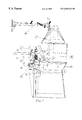
- FIG. 1 is an illustrative layout of an arrangement for seam preparation according to the present invention.
- the circular movement is achieved by means of an electric motor 15 running an angular gear 14 which in its elongation (by way of a thorough shaft) transmits the movement to a work holding fixture 9 assembled on a work drive dog.
- the circular movement is used for seam preparation of pipes/tubes. Thanks to the use of a work holding fixture, the seam preparation can be done down to a length of 50 mm.
- the linear movement is achieved by way of a driving wheel applied on the work holding fixture 9 .
- a plate holder 10 On the feeding ring 8 and on a parallel conveying bar 21 respectively, rests a plate holder 10 .
- the moment between the feeding ring 8 and the plate holder 10 is adjusted by a rubber-covered press roll 4 .
- the linear movement is used for seam preparation of plates.
- Engine-driven gear racks 5 are applied on the machine in order to control the plasma gun 6 vertically and in the direction of the depth.
- Exhaust from the machine is removed from two points: 1) through a suction casing 17 above the cutting area, and 2) through an outlet 13 in the lower part of the machine.
- the machine has a shape with few movable parts which implies that the machine obtains precision in the circular and in the linear movement.
- the movements can be adjusted steplessly when rotation speed of the driving unit has a working range of from 0.5 rpm up to 9 rpm. This results in an advancing speed for the plate holder 10 in between the range 0.35 m/min. Up to 6.3 m/min of stepless adjustment.
Landscapes
- Engineering & Computer Science (AREA)
- Mechanical Engineering (AREA)
- Physics & Mathematics (AREA)
- Plasma & Fusion (AREA)
- Arc Welding In General (AREA)
- Press Drives And Press Lines (AREA)
- Motorcycle And Bicycle Frame (AREA)
- Perforating, Stamping-Out Or Severing By Means Other Than Cutting (AREA)
Abstract
The unique in the construction is a number of important components and parts: a) the plate holder in molded aluminium; its double function and shaping in order to be able to be used as both a holder for plates and also serve for transfer of the circular movement to the linear, b) the driving wheel which facilitates the transfer of the circular movement to the plate holder, c) the superstructure which comprises a device for a press roll and also the parallel conveying bar and to make it possible for adjustment of the frictional pressure between the driving wheel and the plate holder, d) adjustment, through engine-driven gear racks, of the plasma gun for the making of holes.
Description
It is well known that schools for welding, and companies of today use mechanical treatments such as cutting, turning, milling and planning for joint preparation of welding seams. The materials used are stainless steel (alloyed), aluminum and black plate (unalloyed). The teaching of welding can be carried out in such way that the trainee provides samples of plates and/alternatively on pipes and tubes. Seam preparation of plates may be carried out by means of applying the workpiece in a particular machine where use is made of oxygen and acetylene cutting. The method is expensive and time consuming. With respect to scam preparation of pipes/tubes, a number of problems occur. The method is very costly, time-consuming and comprises a number of hazardous operations.
The cutting of the pipe/tube are carried out in a band saw machine, and alternatively by way of cutting wheel.
The pipe/tube are applied to a turning machine for the purpose of chamfering into a correct chamfer angle.
These operations are hazardous with respect to an industrial safety point of view.
The purpose with the present invention is to securely prepare seams for plates as well as pipes/tubes in a cost efficient way, and provide a safe working environment.
The purpose of the machine is to provide for seam preparation for plates as well as pipes/tubes in the same machine. The machine is cost saving, decreases and eliminates the risk for injuries, and provides a high quality to the surfaces prepared. By way of using the combined construction of the machine, circular and linear movements, the stepless driving unit, and that in combination with a thermal cutting operation fulfills the purpose of the invention.
The accompanying drawing, which is included to provide a further understanding of the invention and is incorporated in and constitutes a part of this specification, illustrates a preferred embodiment of the invention and together with the detail description serves to explain the principles of the invention. In the drawing:
FIG. 1 is an illustrative layout of an arrangement for seam preparation according to the present invention.
Referring to FIG. 1, the circular movement is achieved by means of an electric motor 15 running an angular gear 14 which in its elongation (by way of a thorough shaft) transmits the movement to a work holding fixture 9 assembled on a work drive dog. The circular movement is used for seam preparation of pipes/tubes. Thanks to the use of a work holding fixture, the seam preparation can be done down to a length of 50 mm.
The linear movement is achieved by way of a driving wheel applied on the work holding fixture 9. On the feeding ring 8 and on a parallel conveying bar 21 respectively, rests a plate holder 10. The moment between the feeding ring 8 and the plate holder 10 is adjusted by a rubber-covered press roll 4. The linear movement is used for seam preparation of plates.
For the thermal cutting operation, use is made of a plasma aggregate which mixes the protective gases argon, nitrogen and hydrogen in order to provide cutes without oxidation to materials such as stainless steel and aluminum. For unalloyed and low-alloy materials, use is made of ordinary compressed air from existing plants.
Engine-driven gear racks 5 are applied on the machine in order to control the plasma gun 6 vertically and in the direction of the depth.
Exhaust from the machine is removed from two points: 1) through a suction casing 17 above the cutting area, and 2) through an outlet 13 in the lower part of the machine.
With this construction, the machine has a shape with few movable parts which implies that the machine obtains precision in the circular and in the linear movement. The movements can be adjusted steplessly when rotation speed of the driving unit has a working range of from 0.5 rpm up to 9 rpm. This results in an advancing speed for the plate holder 10 in between the range 0.35 m/min. Up to 6.3 m/min of stepless adjustment.
It has been shown in tests that the construction very well fulfills the great expectations and demands for precision and quality in connection with seam preparation.
Claims (8)
1. A device for seam preparation of plates and pipes/tubes in which linear movements are provided for plates, and circular movements are provided for pipes/tubes, wherein the device comprises:
a work holding fixture on which at least one pipe/tube can be arranged for seam preparation, said work holding fixture being rotatable by an electric motor; and
a plate holder on which a plate can be rigidly arranged for seam preparation.
2. The device for seam preparation according to claim 1 , wherein the device further comprises:
a press roll arranged above said work holding fixture, whereby a linear movement is achieved by the work holding fixture which runs said plate holder, and also the press roll is arranged against the plate holder and the work holding fixture.
3. The device for seam preparation according to claim 1 , wherein the movements providing the linear movement and circular movements are stepless.
4. A method of seam preparation using the device of claim 1 , said method comprising utilizing a plasma cutting aggregate for providing cuts without oxidation in stainless steel and aluminum.
5. The device for seam preparation according to claim 1 , wherein the circular movement is achieved by means of an electric motor;
said electric motor runs an angular gear which transmits the movement to a work holding fixture assembled on a work drive dog.
6. The device for seam preparation according to claim 1 , wherein the linear movement is achieved by way of a driving wheel applied on the work holding fixture, and the plate holder rests on a feeding ring and on a parallel conveying bar respectively.
7. The device for seam preparation according to claim 1 , wherein exhaust from the device is removed from two points through a suction casing above a cutting area and through an outlet in a lower part of the device.
8. The device for seam preparation according to claim 1 , wherein engine-driven gear racks are applied on the device in order to control the movement of a plasma gun vertically.
Applications Claiming Priority (3)
| Application Number | Priority Date | Filing Date | Title |
|---|---|---|---|
| SE9804464 | 1998-12-22 | ||
| SE9804464A SE514704C2 (en) | 1998-12-22 | 1998-12-22 | Grout preparation machine for circular and linear movements |
| PCT/SE1999/002381 WO2000040363A1 (en) | 1998-12-22 | 1999-12-16 | An arrangement for seam preparation |
Publications (1)
| Publication Number | Publication Date |
|---|---|
| US6582529B1 true US6582529B1 (en) | 2003-06-24 |
Family
ID=20413787
Family Applications (1)
| Application Number | Title | Priority Date | Filing Date |
|---|---|---|---|
| US09/869,110 Expired - Fee Related US6582529B1 (en) | 1998-12-22 | 1999-12-16 | Arrangement for seam preparation |
Country Status (5)
| Country | Link |
|---|---|
| US (1) | US6582529B1 (en) |
| EP (1) | EP1183129A1 (en) |
| NO (1) | NO20013095L (en) |
| SE (1) | SE514704C2 (en) |
| WO (1) | WO2000040363A1 (en) |
Citations (7)
| Publication number | Priority date | Publication date | Assignee | Title |
|---|---|---|---|---|
| US4143862A (en) | 1975-09-18 | 1979-03-13 | Widder Corporation | Apparatus for cutting pipes, plates and the like |
| US4216945A (en) | 1976-07-02 | 1980-08-12 | Widder Corporation | Apparatus for automatically controlling the cutting of pipes, plates and the like |
| US4349182A (en) | 1975-11-13 | 1982-09-14 | Vernon Tool Company Ltd. | Tape-controlled metal cutting apparatus |
| US4693761A (en) * | 1985-03-22 | 1987-09-15 | Oxytechnik | Process and device for handling workpieces, especially for the thermal separation of profiles with a cutting torch |
| FR2676947A1 (en) | 1991-05-27 | 1992-12-04 | Millois Robert | Numerical-control machine for cutting metal sheets and tubes |
| EP0634247A1 (en) | 1993-07-03 | 1995-01-18 | Urs Hagen | Machine-tool for working large workpieces |
| US5778744A (en) * | 1993-12-11 | 1998-07-14 | Maschinenfabrik Reika-Werk Gmbh | Method and device for position-exact and dimension-exact chamfering of a pipe end |
-
1998
- 1998-12-22 SE SE9804464A patent/SE514704C2/en not_active IP Right Cessation
-
1999
- 1999-12-16 EP EP99965655A patent/EP1183129A1/en not_active Withdrawn
- 1999-12-16 US US09/869,110 patent/US6582529B1/en not_active Expired - Fee Related
- 1999-12-16 WO PCT/SE1999/002381 patent/WO2000040363A1/en not_active Ceased
-
2001
- 2001-06-21 NO NO20013095A patent/NO20013095L/en not_active Application Discontinuation
Patent Citations (7)
| Publication number | Priority date | Publication date | Assignee | Title |
|---|---|---|---|---|
| US4143862A (en) | 1975-09-18 | 1979-03-13 | Widder Corporation | Apparatus for cutting pipes, plates and the like |
| US4349182A (en) | 1975-11-13 | 1982-09-14 | Vernon Tool Company Ltd. | Tape-controlled metal cutting apparatus |
| US4216945A (en) | 1976-07-02 | 1980-08-12 | Widder Corporation | Apparatus for automatically controlling the cutting of pipes, plates and the like |
| US4693761A (en) * | 1985-03-22 | 1987-09-15 | Oxytechnik | Process and device for handling workpieces, especially for the thermal separation of profiles with a cutting torch |
| FR2676947A1 (en) | 1991-05-27 | 1992-12-04 | Millois Robert | Numerical-control machine for cutting metal sheets and tubes |
| EP0634247A1 (en) | 1993-07-03 | 1995-01-18 | Urs Hagen | Machine-tool for working large workpieces |
| US5778744A (en) * | 1993-12-11 | 1998-07-14 | Maschinenfabrik Reika-Werk Gmbh | Method and device for position-exact and dimension-exact chamfering of a pipe end |
Also Published As
| Publication number | Publication date |
|---|---|
| SE9804464L (en) | 2000-06-23 |
| SE514704C2 (en) | 2001-04-02 |
| WO2000040363A1 (en) | 2000-07-13 |
| EP1183129A1 (en) | 2002-03-06 |
| NO20013095D0 (en) | 2001-06-21 |
| NO20013095L (en) | 2001-08-17 |
| SE9804464D0 (en) | 1998-12-22 |
Similar Documents
| Publication | Publication Date | Title |
|---|---|---|
| US4466170A (en) | Adjustable circular insulation saw system | |
| US9884398B2 (en) | Apparatus for processing circular or square tube or bar material to desired shape by freely controlling cutting tool by wireless communication | |
| KR101344343B1 (en) | automatic welding system | |
| AU3366397A (en) | Plant for friction stir welding | |
| US4343207A (en) | Tool for spiral machining | |
| US4979294A (en) | Boiler tube repair method | |
| US6582529B1 (en) | Arrangement for seam preparation | |
| US6578267B2 (en) | Air tool for sectioning a length of tubing | |
| CN206366675U (en) | A kind of bar sawing machine | |
| CN221159098U (en) | Automatic welding tool | |
| CN220921320U (en) | Exhaust pipe welding device | |
| JPH10314949A (en) | Pipe cutting equipment | |
| CN212094769U (en) | Pipeline processing device | |
| CN118455689A (en) | Pipeline groove processing method and processing device | |
| EP0563199B1 (en) | Hand-held electrically operated circular saw with a detachable and rotatable saw unit | |
| CN110076472B (en) | Automatic welding equipment for pipeline circumferential seams | |
| US5193257A (en) | Boiler tube repair apparatus | |
| CN219336502U (en) | Multi-station automatic welding machine turntable | |
| US4619167A (en) | Adjustable circular insulation saw system | |
| CN201455560U (en) | Elbow port cutting machine | |
| CN221582304U (en) | Small-pipe-diameter pipe joint cutting device | |
| CN107283081B (en) | Swing angle adjustable composite welding assembly | |
| CN220921356U (en) | Circumferential weld welding robot | |
| CN219094187U (en) | Double-motor welding device for processing steel support inner pipe | |
| CN222176315U (en) | Pipeline ring welding device |
Legal Events
| Date | Code | Title | Description |
|---|---|---|---|
| REMI | Maintenance fee reminder mailed | ||
| LAPS | Lapse for failure to pay maintenance fees | ||
| STCH | Information on status: patent discontinuation |
Free format text: PATENT EXPIRED DUE TO NONPAYMENT OF MAINTENANCE FEES UNDER 37 CFR 1.362 |
|
| FP | Lapsed due to failure to pay maintenance fee |
Effective date: 20070624 |