US6558292B1 - Method and device for controlling an internal combustion engine - Google Patents
Method and device for controlling an internal combustion engine Download PDFInfo
- Publication number
- US6558292B1 US6558292B1 US09/868,457 US86845701A US6558292B1 US 6558292 B1 US6558292 B1 US 6558292B1 US 86845701 A US86845701 A US 86845701A US 6558292 B1 US6558292 B1 US 6558292B1
- Authority
- US
- United States
- Prior art keywords
- engine
- engine speed
- clutch
- gear change
- speed
- Prior art date
- Legal status (The legal status is an assumption and is not a legal conclusion. Google has not performed a legal analysis and makes no representation as to the accuracy of the status listed.)
- Expired - Lifetime
Links
Images


Classifications
-
- B—PERFORMING OPERATIONS; TRANSPORTING
- B60—VEHICLES IN GENERAL
- B60W—CONJOINT CONTROL OF VEHICLE SUB-UNITS OF DIFFERENT TYPE OR DIFFERENT FUNCTION; CONTROL SYSTEMS SPECIALLY ADAPTED FOR HYBRID VEHICLES; ROAD VEHICLE DRIVE CONTROL SYSTEMS FOR PURPOSES NOT RELATED TO THE CONTROL OF A PARTICULAR SUB-UNIT
- B60W10/00—Conjoint control of vehicle sub-units of different type or different function
- B60W10/04—Conjoint control of vehicle sub-units of different type or different function including control of propulsion units
- B60W10/06—Conjoint control of vehicle sub-units of different type or different function including control of propulsion units including control of combustion engines
-
- B—PERFORMING OPERATIONS; TRANSPORTING
- B60—VEHICLES IN GENERAL
- B60W—CONJOINT CONTROL OF VEHICLE SUB-UNITS OF DIFFERENT TYPE OR DIFFERENT FUNCTION; CONTROL SYSTEMS SPECIALLY ADAPTED FOR HYBRID VEHICLES; ROAD VEHICLE DRIVE CONTROL SYSTEMS FOR PURPOSES NOT RELATED TO THE CONTROL OF A PARTICULAR SUB-UNIT
- B60W10/00—Conjoint control of vehicle sub-units of different type or different function
- B60W10/10—Conjoint control of vehicle sub-units of different type or different function including control of change-speed gearings
- B60W10/11—Stepped gearings
-
- B—PERFORMING OPERATIONS; TRANSPORTING
- B60—VEHICLES IN GENERAL
- B60W—CONJOINT CONTROL OF VEHICLE SUB-UNITS OF DIFFERENT TYPE OR DIFFERENT FUNCTION; CONTROL SYSTEMS SPECIALLY ADAPTED FOR HYBRID VEHICLES; ROAD VEHICLE DRIVE CONTROL SYSTEMS FOR PURPOSES NOT RELATED TO THE CONTROL OF A PARTICULAR SUB-UNIT
- B60W30/00—Purposes of road vehicle drive control systems not related to the control of a particular sub-unit, e.g. of systems using conjoint control of vehicle sub-units
- B60W30/18—Propelling the vehicle
-
- B—PERFORMING OPERATIONS; TRANSPORTING
- B60—VEHICLES IN GENERAL
- B60W—CONJOINT CONTROL OF VEHICLE SUB-UNITS OF DIFFERENT TYPE OR DIFFERENT FUNCTION; CONTROL SYSTEMS SPECIALLY ADAPTED FOR HYBRID VEHICLES; ROAD VEHICLE DRIVE CONTROL SYSTEMS FOR PURPOSES NOT RELATED TO THE CONTROL OF A PARTICULAR SUB-UNIT
- B60W2710/00—Output or target parameters relating to a particular sub-units
- B60W2710/06—Combustion engines, Gas turbines
- B60W2710/0644—Engine speed
Definitions
- the present invention relates to a method and an arrangement in accordance with the preambles to patent claims 1 and 6 respectively.
- a disadvantage of the state of the art is that the sometimes large speed differences and masses involved in such speed adjustment cause considerable clutch wear, even in normal gear changes during normal driving, owing to the aforesaid engine speed reduction when gear changing is initiated.
- One object of the present invention is to eliminate the problems of the state of the art. This is achieved in a method and an arrangement of the kind mentioned in the introduction by means of the features indicated in the characterising parts of patent claims 1 and 6 respectively.
- a system according to the invention thus prevents the risk of coolant boiling in the retarder and makes it possible to dimension the cooling arrangement so that the latter need not operate with the excessive and almost momentary additional heat which may otherwise occur on completion of a gear change procedure. It should be mentioned here that in normal driving it is in principle never, or at least extremely rarely, desirable for the engine speed to be reduced to idling speed.
- sensors for emitting such signals are already known but are conventionally designed, for example, to communicate with a road speed maintainer and/or to make changeover possible in any split gearbox fitted. Such conventional sensors may nevertheless be used in the invention.
- the invention is applicable both in purely mechanical gearboxes with mechanical linkages and in servo-assisted gearboxes.
- Relevant gearboxes include a main gearbox and also, where applicable, a split and/or range gearbox or the like.
- Advanced control systems have recently been developed which adapt the engine speed to the input speed of a gearbox unit on the basis of a number of sensors situated at various points in the driveline, but these systems are applied in such a way that the clutch is not used in normal driving and the speed adjustment is designed to be so accurate that a gear changeover can be initiated directly without operating the clutch.
- Such sophisticated control systems are relatively expensive, however, since they require a more complex structure as regards both the components involved and the software programming of the control system.
- engine speed adjustment or maintenance is initiated by the driver operating an entirely manual or a servo-assisted clutch, but the clutch is otherwise used in a conventional manner.
- the advantage of the present invention is thus that it avoids the speed decrease which occurs with conventional systems, and hence also avoids the problems associated with the latter.
- the invention may thus be used at relatively low cost and in a simple manner without the control system becoming complex.
- the driving data which may require observation and recording include acceleration, vehicle speed, engine speed, power mobilisation and torque extraction.
- the system may be designed to observe some or all of these driving parameters to provide the basis for estimating, when the driver disengages the clutch, an engine speed which is at least in the vicinity of the actual engine speed after the gear change has taken place.
- FIG. 1 depicts schematically a flow diagram of a method according to the invention
- FIG. 2 depicts schematically the control system, including a system according to the invention, in a driveline for a heavy vehicle,
- FIG. 3 depicts schematically the changes in engine speed during a conventional gear change sequence
- FIG. 4 depicts schematically the pattern of engine speed during a gear change sequence applying a system according to the invention.
- This description exemplifies the use of the invention in a vehicle, such as a heavy-duty truck or a bus, in which a combustion engine is used as drive engine for the vehicle, and the vehicle's driveline incorporates a clutch between the engine and the gearbox.
- the engine may for example take the form of a diesel engine.
- FIG. 1 shows a flow diagram of a method according to the invention in which reference 1 denotes the start of the sequence.
- Reference 2 represents the observation of driving parameters such as acceleration, vehicle speed, engine speed, power mobilisation and torque extraction, and reference 3 the recording of relevant driving parameter data, e.g. driving data during the most recent minutes, which are continuously updated in a memory belonging to the system.
- Reference 4 represents the detection of a break in the driveline, e.g. in the form of disengagement of a disc clutch, and the generating and emission of a first signal which is indicative thereof.
- Reference 5 denotes the calculation of a desired engine speed on the basis of relevant driving data, thereby making it possible to estimate an expected change in the driving configuration, e.g.
- an expected upward gear change, an expected downward gear change etc. on the basis of data on, for example, torque extraction, acceleration, vehicle speed, engine speed and/or power mobilisation.
- a control signal which describes said desired engine speed and is transmitted to a system for controlling the engine.
- Reference 6 denotes the action of the engine control system on the engine to achieve the desired engine speed, such as mobilisation of power to achieve the desired engine speed.
- Reference 7 represents the detection of reconnection of the driveline, and reference 8 denotes the end of the sequence.
- FIG. 2 depicts schematically the control system 9 , which advantageously incorporates a system according to the invention integrated into or connected to the normal engine control system.
- Reference 16 denotes a memory for the recording of driving parameters which are relevant in connection with the present invention.
- the engine is denoted by reference 10
- the clutch by 11
- the gearbox which in this example comprises three parts, by 12 , 13 and 14
- a speed sensor for the output speed is denoted by 15 .
- Reference 17 represents the final gear.
- the diagram shows the control system communicating with the engine, with the clutch, with the sensor 15 for the output shaft and with the memory 16 .
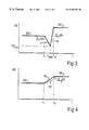
- FIG. 3 depicts in diagram form the engine speed ⁇ as a function of time t in a conventional gear change process in which ⁇ 1 represents the engine speed before the gear change and ⁇ 2 the engine speed after the gear change.
- ⁇ 1 represents the engine speed before the gear change
- ⁇ 2 the engine speed after the gear change.
- a gear change sequence is initiated by the driver depressing a clutch pedal.
- the driver releases the accelerator pedal, resulting, during the curved section 17 , in the engine speed being quickly reduced by ⁇ 1 ⁇ to a minimum speed value ⁇ min at time t min .
- the driver changes the gear or gears in the gearbox and starts letting the clutch pedal rise, which means that there has to be speed adjustment between ⁇ min and ⁇ 2 , i.e. along the curve 18 and amounting to ⁇ 2 ⁇ in the diagram to the completion time t a .
- FIG. 4 shows a corresponding gear change sequence in a system applying the present invention.
- the engine speed is increased from ⁇ 1 to ⁇ 2 , but in this case, owing to the system according to the invention, the control system predicts from relevant driving data an engine speed increase after the gear change so that in the ideal case (represented by the unbroken line at 19 ) the speed prevailing upon completion of the gear change is exactly that required.
- the control system predicts from relevant driving data an engine speed increase after the gear change so that in the ideal case (represented by the unbroken line at 19 ) the speed prevailing upon completion of the gear change is exactly that required.
- there is a certain deviation between the engine speed desired by the control system and ⁇ 2 as illustrated by broken lines at 19 ′ in FIG. 4, resulting in a certain engine speed difference ⁇ 3 ⁇ upon completion of the gear change at time t a .
- FIG. 4 thus shows two examples of speed increase by means of the control system and this is preferred in downward gear changes, but maintaining constant speed upon detection of the break in the driveline is also advantageous, with reference to FIG. 3, and in such cases only a speed adjustment corresponding to the difference between ⁇ 2 and ⁇ 1 would have to be taken care of by the clutch.
- the system applying the method according to the invention is advantageously designed to detect that no normal gear change procedure occurs and hence to allow the engine speed to drop, e.g. to idling speed. This may be achieved by means of a time circuit which disconnects the system and ensures that the engine speed is reduced after a predetermined period of time.
- the invention may in alternative embodiments be modified in whole or in part from what is indicated in the foregoing example. Although the invention exhibits the greatest advantages when used in heavy-duty vehicles, such is not necessarily its only possible area of use. The invention may thus be applied in other types of vehicles, e.g. in ordinary passenger cars, and the engine may be of another known type, e.g. an Otto engine.
Landscapes
- Engineering & Computer Science (AREA)
- Chemical & Material Sciences (AREA)
- Combustion & Propulsion (AREA)
- Transportation (AREA)
- Mechanical Engineering (AREA)
- Automation & Control Theory (AREA)
- Control Of Transmission Device (AREA)
- Control Of Vehicle Engines Or Engines For Specific Uses (AREA)
- Control Of Driving Devices And Active Controlling Of Vehicle (AREA)
Abstract
In a vehicle's driveline, the clutch between drive engine and gearbox has the task of ensuring a final speed adjustment between the engine and the gearbox at the time when the clutch pedal is allowed to rise on completion of a gear change. The invention has the object of reducing the stress on the clutch and the disadvantages which arise from a lengthy sliding-in process with large speed differences. This is achieved by adjusting the engine speed to the gear being engaged, so that only a small speed difference has to be absorbed in the clutch.
Description
The present invention relates to a method and an arrangement in accordance with the preambles to patent claims 1 and 6 respectively.
When driving a heavy vehicle, such as a truck or a bus, provided with a mechanical gearbox and a mechanical clutch, e.g. of disc type, changing down to lower gears is particularly problematical. Depressing the clutch pedal at the time of gear changing results in the engine speed decreasing quickly when the accelerator pedal is released, partly because of the internal friction in the engine. A large number of successive gear changes further reduces the engine speed to idling speed.
Consequently, after the gear change has taken place, the engine has to be speeded up again, which is typically accomplished by the driver allowing the clutch pedal to rise so that the engine is speeded up by being connected to the driveline. Engine speed adjustment is thus brought about via the sliding connection with the gearbox, the final gear and the drive wheels.
A disadvantage of the state of the art is that the sometimes large speed differences and masses involved in such speed adjustment cause considerable clutch wear, even in normal gear changes during normal driving, owing to the aforesaid engine speed reduction when gear changing is initiated. In addition, there is loading of all the other parts of the driveline and inducing of oscillations in the driveline. These result in inferior comfort because of disturbing noise and physical vibration in the vehicle, which is particularly troublesome if the vehicle is a bus.
One object of the present invention is to eliminate the problems of the state of the art. This is achieved in a method and an arrangement of the kind mentioned in the introduction by means of the features indicated in the characterising parts of patent claims 1 and 6 respectively.
It entails using simple means for preventing the undesirable drop in engine speed at the time of clutch disengagement, thereby enabling substantial reduction in clutch loading and wear and in the corresponding loading of other driveline components. Further advantages which may be indicated include simplified driving of a vehicle which is equipped in accordance with the invention, and increased comfort, which is particularly advantageous in buses but is also significant for other types of heavy vehicles. Equipping the vehicle additionally with a hydrodynamic supplementary brake, a so-called retarder, connected to the gearbox results in further advantages in that the retarder cooling, shared with the engine cooling, is maintained at a higher level by means of an arrangement according to the invention than would otherwise be the case upon engine speed reduction. A system according to the invention thus prevents the risk of coolant boiling in the retarder and makes it possible to dimension the cooling arrangement so that the latter need not operate with the excessive and almost momentary additional heat which may otherwise occur on completion of a gear change procedure. It should be mentioned here that in normal driving it is in principle never, or at least extremely rarely, desirable for the engine speed to be reduced to idling speed.
Regarding the indication of the clutch being disengaged, it may be stated that sensors for emitting such signals are already known but are conventionally designed, for example, to communicate with a road speed maintainer and/or to make changeover possible in any split gearbox fitted. Such conventional sensors may nevertheless be used in the invention.
The invention is applicable both in purely mechanical gearboxes with mechanical linkages and in servo-assisted gearboxes. Relevant gearboxes include a main gearbox and also, where applicable, a split and/or range gearbox or the like.
Engine speed control systems are already known and will not be described here.
Advanced control systems have recently been developed which adapt the engine speed to the input speed of a gearbox unit on the basis of a number of sensors situated at various points in the driveline, but these systems are applied in such a way that the clutch is not used in normal driving and the speed adjustment is designed to be so accurate that a gear changeover can be initiated directly without operating the clutch. Such sophisticated control systems are relatively expensive, however, since they require a more complex structure as regards both the components involved and the software programming of the control system. With the system according to the present invention, engine speed adjustment or maintenance is initiated by the driver operating an entirely manual or a servo-assisted clutch, but the clutch is otherwise used in a conventional manner. The advantage of the present invention is thus that it avoids the speed decrease which occurs with conventional systems, and hence also avoids the problems associated with the latter. The invention may thus be used at relatively low cost and in a simple manner without the control system becoming complex.
The driving data which may require observation and recording include acceleration, vehicle speed, engine speed, power mobilisation and torque extraction. Depending on the application, the system may be designed to observe some or all of these driving parameters to provide the basis for estimating, when the driver disengages the clutch, an engine speed which is at least in the vicinity of the actual engine speed after the gear change has taken place.
Further advantages are achieved by the features in the other patent claims and will be described below.
The invention will now be described in more detail on the basis of an embodiment and with reference to the attached drawings, in which:
FIG. 1 depicts schematically a flow diagram of a method according to the invention,
FIG. 2 depicts schematically the control system, including a system according to the invention, in a driveline for a heavy vehicle,
FIG. 3 depicts schematically the changes in engine speed during a conventional gear change sequence, and
FIG. 4 depicts schematically the pattern of engine speed during a gear change sequence applying a system according to the invention.
This description exemplifies the use of the invention in a vehicle, such as a heavy-duty truck or a bus, in which a combustion engine is used as drive engine for the vehicle, and the vehicle's driveline incorporates a clutch between the engine and the gearbox. The engine may for example take the form of a diesel engine.
FIG. 1 shows a flow diagram of a method according to the invention in which reference 1 denotes the start of the sequence. Reference 2 represents the observation of driving parameters such as acceleration, vehicle speed, engine speed, power mobilisation and torque extraction, and reference 3 the recording of relevant driving parameter data, e.g. driving data during the most recent minutes, which are continuously updated in a memory belonging to the system. Reference 4 represents the detection of a break in the driveline, e.g. in the form of disengagement of a disc clutch, and the generating and emission of a first signal which is indicative thereof. Reference 5 denotes the calculation of a desired engine speed on the basis of relevant driving data, thereby making it possible to estimate an expected change in the driving configuration, e.g. an expected upward gear change, an expected downward gear change etc., on the basis of data on, for example, torque extraction, acceleration, vehicle speed, engine speed and/or power mobilisation. Also generated and emitted is a control signal which describes said desired engine speed and is transmitted to a system for controlling the engine. Reference 6 denotes the action of the engine control system on the engine to achieve the desired engine speed, such as mobilisation of power to achieve the desired engine speed. Reference 7 represents the detection of reconnection of the driveline, and reference 8 denotes the end of the sequence.
FIG. 2 depicts schematically the control system 9, which advantageously incorporates a system according to the invention integrated into or connected to the normal engine control system. Reference 16 denotes a memory for the recording of driving parameters which are relevant in connection with the present invention. In the driveline, the engine is denoted by reference 10, the clutch by 11 and the gearbox, which in this example comprises three parts, by 12, 13 and 14, while a speed sensor for the output speed is denoted by 15. Reference 17 represents the final gear. The diagram shows the control system communicating with the engine, with the clutch, with the sensor 15 for the output shaft and with the memory 16.
FIG. 3 depicts in diagram form the engine speed ω as a function of time t in a conventional gear change process in which ω1 represents the engine speed before the gear change and ω2 the engine speed after the gear change. At time ti a gear change sequence is initiated by the driver depressing a clutch pedal. At the same time, the driver releases the accelerator pedal, resulting, during the curved section 17, in the engine speed being quickly reduced by Δ1ω to a minimum speed value ωmin at time tmin. At that time, the driver changes the gear or gears in the gearbox and starts letting the clutch pedal rise, which means that there has to be speed adjustment between ωmin and ω2, i.e. along the curve 18 and amounting to Δ2ω in the diagram to the completion time ta.
FIG. 4 shows a corresponding gear change sequence in a system applying the present invention. In the same way as in FIG. 3, the engine speed is increased from ω1 to ω2, but in this case, owing to the system according to the invention, the control system predicts from relevant driving data an engine speed increase after the gear change so that in the ideal case (represented by the unbroken line at 19) the speed prevailing upon completion of the gear change is exactly that required. Usually, however, there is a certain deviation between the engine speed desired by the control system and ω2, as illustrated by broken lines at 19′ in FIG. 4, resulting in a certain engine speed difference Δ3ω upon completion of the gear change at time ta.
This means that a speed adjustment amounting to Δ3ω is required between the engine and the remainder of the driveline, and this is usually achieved by the driver allowing the clutch pedal to rise.
It should be noted that the invention is applicable to both upward gear changes and downward gear changes and is useful in all types of gear change processes. FIG. 4 thus shows two examples of speed increase by means of the control system and this is preferred in downward gear changes, but maintaining constant speed upon detection of the break in the driveline is also advantageous, with reference to FIG. 3, and in such cases only a speed adjustment corresponding to the difference between ω2 and ω1 would have to be taken care of by the clutch.
To allow engine speed reduction on the occasion, for example, of a shorter or longer stop, the system applying the method according to the invention is advantageously designed to detect that no normal gear change procedure occurs and hence to allow the engine speed to drop, e.g. to idling speed. This may be achieved by means of a time circuit which disconnects the system and ensures that the engine speed is reduced after a predetermined period of time.
The invention may in alternative embodiments be modified in whole or in part from what is indicated in the foregoing example. Although the invention exhibits the greatest advantages when used in heavy-duty vehicles, such is not necessarily its only possible area of use. The invention may thus be applied in other types of vehicles, e.g. in ordinary passenger cars, and the engine may be of another known type, e.g. an Otto engine.
Claims (15)
1. A method for controlling the engine speed of a combustion engine of a vehicle, wherein the vehicle includes a combustion engine, a mechanical gearbox, a driveline between the engine and the gearbox and a manually operable clutch including in the driveline,
the method comprising
detecting and recording driving parameter data for operation of the vehicle and the engine thereof;
breaking the driveline connection between the engine and the gearbox by disconnecting the clutch, detecting the disconnection of the clutch and generating a first signal indicative of the disconnection of the clutch;
determining a desired engine speed which is desired to exist upon completion of a gear change, the determinating is initiated by the first generated signal and the determining is based upon the recorded driving parameter data; and
generating a control signal for controlling the engine speed to be guided toward the desired engine speed upon completion of the gear change.
2. The method of claim 1 , further comprising after generating the control signal, completing a gear change in the mechanical gear box.
3. The method of claim 2 , further comprising after completing of the gear change, reconnecting the clutch and restoring the drive line with the engine operating.
4. The method of claim 1 , wherein the driving parameter data are selected to include one or more of the group consisting of vehicle acceleration, vehicle speed, engine speed, power mobilization of the engine and torque extraction.
5. The method of claim 4 , wherein the gear change is a downward gear change and a desired speed of the engine is an increased speed, as compared with the engine speed before disconnection of the clutch.
6. The method of claim 4 , wherein the gear change is an upward gear change and the desired engine speed is reduced in a controlled manner, as compared with the engine speed before disconnection of the clutch.
7. The method of claim 4 , wherein the gear change is a downward gear change and the engine speed before the break in the driveline and after the control signal is generated is substantially constant.
8. The method of claim 1 , wherein the driving parameter data are selected to include one or more of the group consisting of vehicle acceleration, vehicle speed, engine speed, power mobilization of the engine and torque extraction.
9. The method of claim 1 , wherein the gear change is an upward gear change and the desired engine speed is reduced in a controlled manner, as compared with the engine speed before disconnection of the clutch.
10. The method of claim 1 , wherein the gear change is a downward gear change and the engine speed before the break in the driveline and after the control signal is generated is substantially constant.
11. An arrangement for controlling the engine speed of a combustion engine in a vehicle, wherein the vehicle includes a combustion engine, a mechanical gearbox operable for changing gears in an upward change and in a downward change, a driveline between the engine and the gearbox for driving the gearbox from the engine, the arrangement comprising:
a manually operable clutch incorporated in the driveline and selectively operable to break the driveline connection between the engine and the gearbox and restore the driveline connection;
a detector for detecting a break in the driveline upon disengagement of the clutch and for then generating a first signal indicative of the break in the driveline;
a control system operable for observing and recording driving parameter data of operation of the vehicle; the control system being activated by the first signal and being adapted to determine a desired engine speed intended upon completion of a gear change in the gear box, which desired engine speed is determined by the control system based on the driving parameter data;
the control system being operable to generate a control signal to act upon the engine for guiding the engine speed toward the desired speed.
12. The arrangement of claim 11 , wherein the driving parameter data are selected to include one or more of the group consisting of vehicle acceleration, vehicle speed, engine speed, power mobilization of the engine and torque extraction.
13. The arrangement of claim 11 , wherein when the mechanical gearbox is operated for a downward gear change, the control system is operable to set a desired engine speed that is to be increased, as compared with the engine speed before disconnection of the clutch.
14. The arrangement of claim 11 , wherein when the mechanical gearbox is operated for an upward gear change, the control system is operable to cause the engine speed to be reduced in a controlled manner toward the desired speed, as compared with the engine speed before disconnection of the clutch.
15. The arrangement of claim 11 , wherein when the mechanical gearbox is operated for a downward change, the control system is operable so that the engine speed is arranged to be substantially constant from the speed before the disconnection of the clutch and after disconnection of the clutch.
Applications Claiming Priority (3)
| Application Number | Priority Date | Filing Date | Title |
|---|---|---|---|
| SE9804342A SE511660C2 (en) | 1998-12-16 | 1998-12-16 | Method and apparatus for controlling an internal combustion engine |
| SE9804342 | 1998-12-16 | ||
| PCT/SE1999/002326 WO2000035702A1 (en) | 1998-12-16 | 1999-12-13 | Method and device for controlling an internal combustion engine |
Publications (1)
| Publication Number | Publication Date |
|---|---|
| US6558292B1 true US6558292B1 (en) | 2003-05-06 |
Family
ID=20413674
Family Applications (1)
| Application Number | Title | Priority Date | Filing Date |
|---|---|---|---|
| US09/868,457 Expired - Lifetime US6558292B1 (en) | 1998-12-16 | 1999-12-13 | Method and device for controlling an internal combustion engine |
Country Status (5)
| Country | Link |
|---|---|
| US (1) | US6558292B1 (en) |
| EP (1) | EP1150856B1 (en) |
| DE (1) | DE69915129T2 (en) |
| SE (1) | SE511660C2 (en) |
| WO (1) | WO2000035702A1 (en) |
Cited By (2)
| Publication number | Priority date | Publication date | Assignee | Title |
|---|---|---|---|---|
| US20150166067A1 (en) * | 2012-03-30 | 2015-06-18 | Scania Cv Ab | System and method for controlling the speed of an engine |
| CN112483263A (en) * | 2020-12-03 | 2021-03-12 | 重庆红江机械有限责任公司 | Manual speed regulation control device |
Families Citing this family (1)
| Publication number | Priority date | Publication date | Assignee | Title |
|---|---|---|---|---|
| GB2444941A (en) | 2006-11-30 | 2008-06-25 | Ford Global Tech Llc | A method of controlling engine speed during a manual gearshift |
Citations (8)
| Publication number | Priority date | Publication date | Assignee | Title |
|---|---|---|---|---|
| US4698763A (en) * | 1985-03-15 | 1987-10-06 | Eaton Corporation | Automatic mechanical transmission control |
| US4817776A (en) * | 1985-03-29 | 1989-04-04 | Toshiaki Tateno | Starting control apparatus for automatic transmission system |
| US4852006A (en) * | 1988-04-18 | 1989-07-25 | Eaton Corporation | Amt off-highway downshift logic |
| WO1991002662A1 (en) | 1989-08-25 | 1991-03-07 | Zahnradfabrik Friedrichshafen Ag | Control device |
| US5081583A (en) * | 1988-12-12 | 1992-01-14 | Diesel Kiki Co., Ltd. | Automatic control system for gear transmission |
| US5095434A (en) * | 1989-01-13 | 1992-03-10 | Iveco Fiat S.P.A. | Motor vehicle drive control system |
| US5569115A (en) * | 1995-07-27 | 1996-10-29 | Rockwell International Corporation | Engine speed synchronization system for assisting in manual transmission shifting |
| EP0873902A1 (en) | 1997-04-23 | 1998-10-28 | Daimler-Benz Aktiengesellschaft | Method of gear shifting for an unsynchronised gearbox |
-
1998
- 1998-12-16 SE SE9804342A patent/SE511660C2/en not_active IP Right Cessation
-
1999
- 1999-12-13 WO PCT/SE1999/002326 patent/WO2000035702A1/en not_active Ceased
- 1999-12-13 EP EP99963824A patent/EP1150856B1/en not_active Expired - Lifetime
- 1999-12-13 US US09/868,457 patent/US6558292B1/en not_active Expired - Lifetime
- 1999-12-13 DE DE69915129T patent/DE69915129T2/en not_active Expired - Fee Related
Patent Citations (9)
| Publication number | Priority date | Publication date | Assignee | Title |
|---|---|---|---|---|
| US4698763A (en) * | 1985-03-15 | 1987-10-06 | Eaton Corporation | Automatic mechanical transmission control |
| US4817776A (en) * | 1985-03-29 | 1989-04-04 | Toshiaki Tateno | Starting control apparatus for automatic transmission system |
| US4852006A (en) * | 1988-04-18 | 1989-07-25 | Eaton Corporation | Amt off-highway downshift logic |
| US5081583A (en) * | 1988-12-12 | 1992-01-14 | Diesel Kiki Co., Ltd. | Automatic control system for gear transmission |
| US5095434A (en) * | 1989-01-13 | 1992-03-10 | Iveco Fiat S.P.A. | Motor vehicle drive control system |
| WO1991002662A1 (en) | 1989-08-25 | 1991-03-07 | Zahnradfabrik Friedrichshafen Ag | Control device |
| US5569115A (en) * | 1995-07-27 | 1996-10-29 | Rockwell International Corporation | Engine speed synchronization system for assisting in manual transmission shifting |
| WO1997004982A1 (en) | 1995-07-27 | 1997-02-13 | Rockwell International Corporation | Engine speed synchronization system for assisting in manual transmission shifting |
| EP0873902A1 (en) | 1997-04-23 | 1998-10-28 | Daimler-Benz Aktiengesellschaft | Method of gear shifting for an unsynchronised gearbox |
Cited By (3)
| Publication number | Priority date | Publication date | Assignee | Title |
|---|---|---|---|---|
| US20150166067A1 (en) * | 2012-03-30 | 2015-06-18 | Scania Cv Ab | System and method for controlling the speed of an engine |
| CN112483263A (en) * | 2020-12-03 | 2021-03-12 | 重庆红江机械有限责任公司 | Manual speed regulation control device |
| CN112483263B (en) * | 2020-12-03 | 2022-07-19 | 重庆红江机械有限责任公司 | Manual speed regulation control device |
Also Published As
| Publication number | Publication date |
|---|---|
| SE9804342D0 (en) | 1998-12-16 |
| EP1150856A1 (en) | 2001-11-07 |
| EP1150856B1 (en) | 2004-02-25 |
| SE9804342L (en) | 1999-11-01 |
| WO2000035702A1 (en) | 2000-06-22 |
| DE69915129T2 (en) | 2004-09-16 |
| DE69915129D1 (en) | 2004-04-01 |
| SE511660C2 (en) | 1999-11-01 |
Similar Documents
| Publication | Publication Date | Title |
|---|---|---|
| US6482123B2 (en) | Method of controlling heat buildup in a clutch | |
| KR100237840B1 (en) | Engine flywheel torque determination method and device | |
| KR100237839B1 (en) | Engine auxiliary torque and engine reduction ratio determination method and device | |
| US5928110A (en) | Power train with automated clutch for use in motor vehicles | |
| JP5254366B2 (en) | Method and apparatus for automatic or semi-automatic selection of a good starting gear of a vehicle | |
| US8095286B2 (en) | Method for controlling shifts in an automated gearshift transmission | |
| JPH11503382A (en) | Control device for automatic operating clutch | |
| US5439425A (en) | Method and apparatus for controlling engagement and disengagement of the clutch as a function of displacements between engine and vehicle body | |
| EP1046840A2 (en) | Torque converter lockup control | |
| US5759131A (en) | Control of an automatic clutch | |
| US6126569A (en) | Starting and driveline shock protection control method and system | |
| KR20220000027A (en) | System and method for controlling engine torque of vehicle | |
| US6142909A (en) | Device for controlling a starting process of a motor vehicle | |
| JPH1071875A (en) | Automobile and method to be applied to this automobile | |
| KR102019606B1 (en) | Traction control method of vehicle | |
| US6461273B1 (en) | Automated transmission upshift brake control | |
| KR20200068132A (en) | Auxiliary brake control system of vehicle | |
| US6558292B1 (en) | Method and device for controlling an internal combustion engine | |
| EP0839684B1 (en) | A system for controlling parking and hill-starting of a motor-vehicle | |
| EP1184607A1 (en) | A control device for an actuator applied in a transmission | |
| CN112969609A (en) | Method and drive controller for operating at least two drive motors during a load change, and motor vehicle having a drive controller | |
| EP1158218B1 (en) | Automated transmission upshift control with upshift brake thermal protection | |
| US20050085977A1 (en) | Device for controlling a start of a vehicle | |
| US6461272B1 (en) | Vehicle synchronization algorithm for driveline protection | |
| SE534166C2 (en) | Method and computer program for improving the drivability of a motor vehicle |
Legal Events
| Date | Code | Title | Description |
|---|---|---|---|
| AS | Assignment |
Owner name: SCANIA CV AKTIEBOLAG (PUBL), SWEDEN Free format text: ASSIGNMENT OF ASSIGNORS INTEREST;ASSIGNOR:SODERMAN, GORAN;REEL/FRAME:012193/0054 Effective date: 20010705 |
|
| STCF | Information on status: patent grant |
Free format text: PATENTED CASE |
|
| FPAY | Fee payment |
Year of fee payment: 4 |
|
| FPAY | Fee payment |
Year of fee payment: 8 |
|
| FPAY | Fee payment |
Year of fee payment: 12 |