US6543822B1 - Self-presenting secondary hood latch assembly - Google Patents
Self-presenting secondary hood latch assembly Download PDFInfo
- Publication number
- US6543822B1 US6543822B1 US09/659,612 US65961200A US6543822B1 US 6543822 B1 US6543822 B1 US 6543822B1 US 65961200 A US65961200 A US 65961200A US 6543822 B1 US6543822 B1 US 6543822B1
- Authority
- US
- United States
- Prior art keywords
- release
- slot
- handle
- spring
- rotation stop
- Prior art date
- Legal status (The legal status is an assumption and is not a legal conclusion. Google has not performed a legal analysis and makes no representation as to the accuracy of the status listed.)
- Expired - Fee Related, expires
Links
- 230000008901 benefit Effects 0.000 description 5
- 238000004519 manufacturing process Methods 0.000 description 5
- 238000009434 installation Methods 0.000 description 3
- 238000012986 modification Methods 0.000 description 3
- 230000004048 modification Effects 0.000 description 3
- 230000003247 decreasing effect Effects 0.000 description 2
- 238000007792 addition Methods 0.000 description 1
- 230000000712 assembly Effects 0.000 description 1
- 238000000429 assembly Methods 0.000 description 1
- 238000004806 packaging method and process Methods 0.000 description 1
- 238000012800 visualization Methods 0.000 description 1
Images


Classifications
-
- E—FIXED CONSTRUCTIONS
- E05—LOCKS; KEYS; WINDOW OR DOOR FITTINGS; SAFES
- E05B—LOCKS; ACCESSORIES THEREFOR; HANDCUFFS
- E05B83/00—Vehicle locks specially adapted for particular types of wing or vehicle
- E05B83/16—Locks for luggage compartments, car boot lids or car bonnets
- E05B83/24—Locks for luggage compartments, car boot lids or car bonnets for car bonnets
-
- Y—GENERAL TAGGING OF NEW TECHNOLOGICAL DEVELOPMENTS; GENERAL TAGGING OF CROSS-SECTIONAL TECHNOLOGIES SPANNING OVER SEVERAL SECTIONS OF THE IPC; TECHNICAL SUBJECTS COVERED BY FORMER USPC CROSS-REFERENCE ART COLLECTIONS [XRACs] AND DIGESTS
- Y10—TECHNICAL SUBJECTS COVERED BY FORMER USPC
- Y10S—TECHNICAL SUBJECTS COVERED BY FORMER USPC CROSS-REFERENCE ART COLLECTIONS [XRACs] AND DIGESTS
- Y10S292/00—Closure fasteners
- Y10S292/14—Hood latches
-
- Y—GENERAL TAGGING OF NEW TECHNOLOGICAL DEVELOPMENTS; GENERAL TAGGING OF CROSS-SECTIONAL TECHNOLOGIES SPANNING OVER SEVERAL SECTIONS OF THE IPC; TECHNICAL SUBJECTS COVERED BY FORMER USPC CROSS-REFERENCE ART COLLECTIONS [XRACs] AND DIGESTS
- Y10—TECHNICAL SUBJECTS COVERED BY FORMER USPC
- Y10T—TECHNICAL SUBJECTS COVERED BY FORMER US CLASSIFICATION
- Y10T292/00—Closure fasteners
- Y10T292/08—Bolts
- Y10T292/1043—Swinging
- Y10T292/1044—Multiple head
- Y10T292/1045—Operating means
Definitions
- the present invention generally relates to a latch assembly and, more particularly, to a self-presenting secondary latch assembly for maintaining a hood of a motor vehicle or other hinged panel in a partially opened position.
- Vehicle hoods are typically provided with a primary latch and a secondary or safety latch. Hoods on such vehicles are biased upwardly when the primary latch is released and are latched by the secondary latch in a partially opened position when a striker member engages the secondary latch. Releasing the secondary latch allows the hood to enter a fully opened position.
- a secondary latch assembly comprises, in combination, a mounting bracket, a release hook pivotally mounted to the mounting bracket, and a handle mechanism pivotally mounted to the mounting bracket.
- the release hook is movable between a locked position and a released position and has a slot having a first end and a second end.
- the handle mechanism has a rotation stop that is positioned within the slot of the release hook and that is movable between the first and second ends of the slot.
- the handle mechanism is movable between a first position where the rotation stop is positioned at the first end of the slot, a second position where the rotation stop is positioned at the second end of the slot, and a third position wherein the handle mechanism is rotated from its second position while the rotation stop is positioned at the second end of the slot so that the rotation stop urges the release hook from its locked position to its released position.
- the secondary latch assembly may include biasing means for biasing the release hook in the locked position and may also include biasing means for biasing the handle mechanism in the second position.
- the handle mechanism comprises a release handle pivotally mounted to the mounting bracket and a striker plate connected to the release handle.
- the handle mechanism comprises a striker plate pivotally mounted to the mounting bracket, a release handle pivotally mounted to the mounting bracket remote from the striker plate, and a connector mechanism operatively interconnecting the striker plate and the release handle.
- a secondary latch assembly comprises, in combination, a mounting bracket, a release hook pivotally mounted to the mounting bracket about an axis, and a handle mechanism pivotally mounted to the mounting bracket.
- the release hook is movable between a locked position and a released position and has a slot having a first end and a second end.
- the slot is positioned a spaced distance from the axis about which the release hook is pivotally mounted.
- the handle mechanism has a rotation stop that is positioned within the slot of the release hook and that is movable between the first and second ends of the slot.
- the handle mechanism is movable between a first position where the rotation stop is positioned at the first end of the slot, a second position where the rotation stop is positioned at the second end of the slot, and a third position where the handle mechanism is rotated from its second position while the rotation stop is positioned at the second end of the slot so that the rotation stop urges the release hook from its locked position to its released position.
- a secondary latch assembly comprises, in combination, a mounting bracket, a release hook pivotally mounted to the mounting bracket about a first axis, and a handle mechanism.
- the release hook is movable between a locked position and a released position and has a slot having a first end and a second end.
- the handle mechanism comprises a striker plate pivotally mounted to the mounting bracket, a release handle, a connector mechanism that operatively interconnects the release handle and the striker plate, and a rotation stop attached to the striker plate.
- the release handle is pivotally mounted to the mounting bracket about a second axis a spaced distance from the first axis. The second axis is parallel to the first axis.
- the rotation stop is positioned within the slot of the release hook and is movable between the first and second ends of the slot.
- the handle mechanism is movable between a first position where the rotation stop is positioned at the first end of the slot, a second position where the rotation stop is positioned at the second end of the slot, and a third position wherein the handle mechanism is rotated from its second position while the rotation stop is positioned at the second end of the slot so that the rotation stop urges the release hook from its locked position to its released position.
- a secondary latch assembly comprises, in combination a mounting bracket, a release hook pivotally mounted to the mounting bracket about an axis, and a release handle.
- the release handle is pivotally mounted to the mounting bracket about the axis.
- the release hook movable between a locked position and a released position and has a slot having a first end and a second end.
- the handle has a rotation stop that is positioned within the slot of the release hook. The rotation stop is movable between the first and second ends of the slot.
- the handle is movable between a first position where the rotation stop is positioned at the first end of the slot, a second position where the rotation stop is positioned at the second end of the slot, and a third position wherein the handle is rotated from its second position while the rotation stop is positioned at the second end of the slot so that the rotation stop urges the release hook from its locked position to its released position.
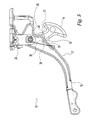
- FIG. 1 is an exploded perspective view of a secondary latch assembly according to a preferred embodiment of the present invention
- FIG. 2 is a rear plan view of the secondary latch assembly of FIG. 1;
- FIG. 3 is a top plan view of the secondary latch assembly of FIGS. 1 and 2;
- FIG. 4 is a side plan view of the secondary latch assembly of FIG. 2 showing the release handle is in a closed position;
- FIG. 5 is a side plan view of the secondary latch assembly of FIG. 2 showing the release handle is in a presented position
- FIG. 6 is a side plan view of the secondary latch assembly of FIG. 2 showing the release handle is in a released position
- FIG. 7 is a side plan view of the secondary latch assembly of FIGS. 4, 5 , and 6 showing the full range of motion of the release handle and the release hook;
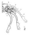
- FIG. 8 is a side plan view of a secondary latch assembly according to an alternative preferred embodiment of the present invention showing the assembly when the hood of the vehicle is closed;
- FIG. 9 is a side plan view of a secondary latch assembly of FIG. 8 showing the assembly when the primary latch has been released;
- FIG. 10 is a side plan view of a secondary latch assembly of FIG. 8 showing the assembly when the assembly has been engaged by a striker;
- FIG. 11 is a side plan view of a secondary latch assembly of FIG. 8 showing the assembly when the release hook has been released from the striker;
- FIG. 12 is a side plan view of a secondary latch assembly of FIG. 8 showing the assembly when the release hook has moved above the striker.
- FIGS. 1-12 show a secondary hood latch assembly 10 for a motor vehicle, such as an automobile, according to the present invention.
- the illustrated embodiments of the present invention are particularly adapted for use with an automobile hood that is hinged for movement between a fully closed position and a fully opened position and is biased to move toward the fully opened position.
- the secondary latch assembly 10 is adapted to maintain the hood in a partially opened position after a primary latch releases the hood from the fully closed position.
- the present invention can be utilized with any apparatus or system having a panel portion hinged for movement with respect to an enclosure portion and having and a primary and secondary latch for opening the panel portion.
- the preferred embodiments of the secondary hood latch assembly 10 include a mounting bracket 12 , a release hook 14 , a handle mechanism 17 , and rotation means 18 .
- the mounting bracket 12 is used to mount the assembly 10 to the underside of a hood (not shown).
- the mounting bracket 12 preferably includes a striker 20 for use with a primary hood latch 60 (shown in FIGS. 8-12) for maintaining the hood in a closed position.
- the secondary hood latch assembly 10 engages a striker 21 (shown in FIGS. 4-12) to limit the upward movement of the hood until the release hook 14 is caused to release the striker 21 , as more fully described below.
- the release hook 14 and the handle mechanism 17 are pivotally mounted to the mounting bracket 12 about a common rotational axis using a pivot pin 22 .
- the release hook 14 is movable between (1) a locked position, as shown in FIGS. 4 and 5, where the release hook 14 will engage the striker 21 when the hood is in a partially opened position and (2) a released position, as shown in FIG. 6, allowing the hood to be fully opened.
- the handle mechanism 17 preferably comprises a release handle 16 and is preferably movable between (1) a first or closed position, as shown in FIG. 4, where the release handle 16 is retracted; (2) a second or presented position, as shown in FIG.
- release handle 16 is presented to a user when the hood is held in a partially opened position; and (3) a third or released position, as shown in FIG. 6, that causes the release hook 14 to move to its released position allowing the hood to be fully opened.
- the release handle 16 When the release handle 16 is in its closed position, the release handle 16 may be retracted within the enclosure portion of the vehicle (not shown).
- the release handle 16 When the release handle 16 is in its presented position, the release handle 16 is positioned between the hood and the enclosure portion of the vehicle so that the release handle 16 is visible to a user in front of the hood.
- the release handle 16 is illustrated as being attached to the pivot pin 22 , it is noted that the release handle 16 may be remotely positioned from the mounting bracket 12 . It is also noted that the present invention may be used without a mounting bracket 12 by mounting the assembly 10 directly to a structure such as an automobile hood.
- the mounting bracket 12 preferably includes a first pivot pin mounting portion 24 and a second pivot pin mounting portion 26 for mounting the pivot pin 22 .
- the second pivot pin mounting portion 26 is preferably attached to the mounting bracket 12 with two mounting pins or rivets 28 (shown in FIG. 1 ).
- the second pivot pin mounting portion 26 also includes a slot 30 for accepting a flange 32 on the release hook 14 for limiting the rotational movement of the release hook 14 .
- the flange 32 contacts one end of the slot 30
- the release hook 14 is in its released position, the flange 32 contacts-the-other end of the slot 30 .
- the secondary hood latch assembly 10 includes rotation means 18 for controlling the rotation of the release hook 14 and the rotation of the handle mechanism 17 .
- the rotation means 18 allow the release handle 16 to move between its closed position and its presented position while the release hook 14 is maintained in its locked position.
- the rotation means 18 further allow the release handle 16 to rotate the release hook 14 to its released position as the release handle 16 rotates to its released position.
- the rotation means 18 include a rotation stop 34 that is positioned in a slot 36 in the release hook 14 .
- the slot 36 is positioned a spaced distance from the axis about which the release hook 14 is pivotally mounted.
- the slot 36 is preferably arcuate in shape, but other shapes of slots will be readily apparent to those skilled in the art given the benefit of this disclosure.
- the rotation stop 34 is connected to the release handle 16 so that the rotation stop 34 moves as the release handle 16 rotates.
- the rotation stop 34 moves between a first end 40 and a second end 38 of the slot 36 without affecting the position of the release hook 14 .
- the rotation stop 34 urges the release hook 14 toward its released position.
- the rotation stop 34 is positioned at the first end 40 of the slot 36 when the release handle 16 is in its closed position. As illustrated in FIG.
- the rotation stop 34 is positioned at the second end 38 of the slot 36 when the release handle 16 is in its presented position. As illustrated in FIG. 6, the release handle 16 enters its released position by rotating while the rotation stop 34 is positioned in the second end 38 of the slot 36 so that the release hook 14 is forced to move from its locked position to its released position.
- the assembly 10 preferably includes a first biasing means for biasing the release handle 16 in its presented position.
- the biasing means may comprise, for example, a spring 44 attached to the pivot pin 22 with a first end fixedly attached to the pivot pin 22 and a second end connected to a slotted flange 45 on the release handle 16 .
- the spring 44 biases the release handle 16 toward its presented position where the rotation stop 34 contacts the second end 38 of the slot 36 .
- a clip 46 may also be used to separate the spring 44 from the mounting bracket 12 .
- the first biasing means present the handle 16 to a user when the primary hood latch is released so that the secondary latch assembly 10 is self-presenting.
- the assembly 10 preferably includes a second biasing means for biasing the release hook 14 in its locked position.
- the second biasing means may comprise, for example, a spring 50 attached to the pivot pin 22 with one end connected to a second slotted flange 52 on the release hook 14 and a second end connected to a third slotted flange 54 on the second pivot pin mounting portion 26 of the mounting bracket 12 .
- the second biasing means biasing the release hook 14 opposes, and creates a much stronger force than, the force created by the first biasing means biasing the rotation stop 34 against the second end 38 of the slot 36 . In this manner, the release hook 14 will remain in the locked position even when the first biasing means are biasing the rotation stop 34 against the second end 38 of the slot 36 to present the release handle 16 .
- the handle mechanism 17 also includes a striker plate 56 that is connected with the release handle 16 so that rotation of the release handle 16 will rotate the striker plate 56 and rotation of the striker plate 56 will rotate the release handle 16 .
- the striker plate 56 is used to position the release handle 16 in its closed position when the hood is latched by the primary hood latch.
- the striker 21 for the secondary latch assembly 10 contacts the striker plate 56 and forces the striker plate 56 to rotate.
- the rotation of the striker plate 56 rotates the rotation stop 34 to the first end 40 of the slot 36 and rotates the release handle 16 to its closed position.
- the handle mechanism 17 includes a release handle 16 , a connector mechanism 58 , and a striker plate 56 .
- the striker plate 56 is pivotally mounted to the pivot pin 22 about a first rotational axis.
- the release handle 16 is pivotally mounted to the mounting bracket 12 about a second rotational axis at a position that is remote from pivot pin 22 .
- the connector mechanism 58 operatively connects the release handle 16 to striker plate 56 .
- the rotation stop 34 is attached to the striker plate 56 .
- the connector mechanism 58 advantageously permits the handle 16 to be located remote from the striker plate 56 and the rotation stop 34 , thereby providing greater flexibility in packaging of the secondary hood latch assembly 10 .
- the release hook 14 and the striker plate 56 are coaxial and the first and second rotational axes are parallel.
- the alternative preferred embodiment will be used to describe the operation of the secondary hood latch assembly 10 in connection with the opening of a hood of an automobile having a primary hood latch 60 .
- the hood (not shown) is in a fully closed position and the striker 20 attached to the mounting bracket 12 is latched within the primary hood latch 60 .
- a striker 21 is contacting the striker plate 56 and maintaining the release handle 16 in its closed position within the hood.
- the release hook 14 is maintained in its locked position by spring 50 (not shown).
- the primary hood latch 60 has released the striker 20 on the mounting bracket 12 and the hood has risen to a point where the striker 21 has disengaged the striker plate 56 .
- Spring 44 (not shown) has rotated the release handle 16 to its presented position and rotated the rotation stop 34 to the second end 38 of the slot 36 .
- the release hook 14 is maintained in its locked position by spring 50 (not shown).
- the hood has risen to a point where the striker 21 has engaged the release hook 14 .
- the assembly 10 limits any further upward movement of the hood toward its opened position.
- the release handle 16 remains biased in its presented position and the release hook 14 remains in its locked position engaged with the striker 21 . In this position, the release handle 16 is presented to a user and is visible from the outside of the hood enclosure.
- the hood has risen to a point where the release hook 14 is above the striker 21 . In this position, the hood is free to move to its fully opened position.
- the release hook 14 has returned to its locked position due to spring 50 (not shown) and the release handle 16 is maintained in its presented position due to spring 44 (not shown).
- the curved bottom surface 62 of the release hook 14 contacts the striker 21 at the position shown in FIG. 12 .
- the striker 21 forces the release hook 14 to pivot from its locked position to its released position.
- the curved bottom surface 62 slides along the striker 21 as the release hook 14 pivots from its locked position to its released position.
- the spring 50 biases the release hook 14 back to its locked position.
- the primary hood latch 60 engages and latches the striker 20 on the mounting bracket 12 .
- the striker 21 contacts the striker plate 56 and forces the rotation stop 34 to rotate to the first end 40 in the slot 36 and the release handle 16 to pivot to its closed position, as illustrated in FIG. 8 .
Landscapes
- Lock And Its Accessories (AREA)
Abstract
Description
Claims (24)
Priority Applications (1)
| Application Number | Priority Date | Filing Date | Title |
|---|---|---|---|
| US09/659,612 US6543822B1 (en) | 2000-09-11 | 2000-09-11 | Self-presenting secondary hood latch assembly |
Applications Claiming Priority (1)
| Application Number | Priority Date | Filing Date | Title |
|---|---|---|---|
| US09/659,612 US6543822B1 (en) | 2000-09-11 | 2000-09-11 | Self-presenting secondary hood latch assembly |
Publications (1)
| Publication Number | Publication Date |
|---|---|
| US6543822B1 true US6543822B1 (en) | 2003-04-08 |
Family
ID=24646070
Family Applications (1)
| Application Number | Title | Priority Date | Filing Date |
|---|---|---|---|
| US09/659,612 Expired - Fee Related US6543822B1 (en) | 2000-09-11 | 2000-09-11 | Self-presenting secondary hood latch assembly |
Country Status (1)
| Country | Link |
|---|---|
| US (1) | US6543822B1 (en) |
Cited By (14)
| Publication number | Priority date | Publication date | Assignee | Title |
|---|---|---|---|---|
| US20050156447A1 (en) * | 2003-10-24 | 2005-07-21 | Bryan Bishop | Pop-up striker |
| US20060006660A1 (en) * | 2004-06-22 | 2006-01-12 | Seo Chang S | Hood latch assembly for a vehicle |
| US20070246952A1 (en) * | 2006-03-30 | 2007-10-25 | Beauchamp Jason A | Self-presenting non-excitable secondary hood latch assembly |
| CN102765426A (en) * | 2011-05-04 | 2012-11-07 | 现代自动车株式会社 | Hood latch for vehicle |
| GB2523648A (en) * | 2015-01-27 | 2015-09-02 | Daimler Ag | Hood assembly for a commercial vehicle, in particular a truck |
| WO2016138932A1 (en) * | 2015-03-02 | 2016-09-09 | Toyota Motor Europe Nv/Sa | Auxiliary hood lock structure |
| US9840858B2 (en) * | 2014-05-29 | 2017-12-12 | Ford Global Technologies, Llc | Deployable hood release handle |
| US10975600B2 (en) * | 2015-03-27 | 2021-04-13 | Kiekert Ag | Motor vehicle lock |
| US11220849B2 (en) | 2017-04-14 | 2022-01-11 | Mitsui Kinzoku Act Corporation | Hood lock apparatus |
| JP2022006973A (en) * | 2020-06-25 | 2022-01-13 | 株式会社クボタ | Work platform |
| US11268297B2 (en) * | 2015-07-09 | 2022-03-08 | Kiekert Ag | Securing device for front hoods, comprising an electric drive |
| US20220127876A1 (en) * | 2020-10-22 | 2022-04-28 | Overhead Door Corporation | Interior Handle for Upward Acting Vehicle Door |
| US11414904B2 (en) | 2018-05-04 | 2022-08-16 | Magna BOCO GmbH | Double pull closure latch for front trunk having emergency release |
| US12054973B2 (en) | 2020-10-02 | 2024-08-06 | Magna Closures Inc. | Double pull closure latch assembly for hood and frunk motor vehicle applications |
Citations (22)
| Publication number | Priority date | Publication date | Assignee | Title |
|---|---|---|---|---|
| US1097155A (en) * | 1914-02-28 | 1914-05-19 | Samuel F Adams | Car-door lock. |
| US1874230A (en) * | 1931-09-08 | 1932-08-30 | Ternstedt Mfg Co | Hood latch |
| US2028954A (en) * | 1934-10-10 | 1936-01-28 | Grand Rapids Brass Co | Latch |
| US2237232A (en) * | 1938-11-22 | 1941-04-01 | Le Roy H Kiesling | Dumbwaiter biparting door coupling means |
| US2476062A (en) * | 1945-10-08 | 1949-07-12 | Jr Silas A Pierce | Permutation lock container |
| US3117731A (en) * | 1960-11-17 | 1964-01-14 | Westinghouse Electric Corp | Luminaire |
| US4382482A (en) * | 1981-05-13 | 1983-05-10 | International Harvester Co. | Secondary hood latch |
| US4456289A (en) | 1982-09-30 | 1984-06-26 | Metra Electronics Corporation | Add-on locking mechanism for a vehicle hood |
| US4530412A (en) | 1984-04-12 | 1985-07-23 | General Motors Corporation | Vehicle hood support and secondary latch |
| US4756562A (en) | 1986-11-26 | 1988-07-12 | Ryerson & Haynes, Inc. | Latch assembly for vehicles |
| US4896907A (en) | 1986-11-18 | 1990-01-30 | Ohi Seisakusho Co., Ltd. | Locking device for a vehicle |
| US4917417A (en) | 1989-02-24 | 1990-04-17 | General Motors Corporation | Hood latch assembly having unitary latching lever which functions both as a primary and secondary latch |
| US4917420A (en) | 1989-02-21 | 1990-04-17 | General Motors Corporation | Low effort cable release hood latch assembly |
| US4961601A (en) | 1988-08-29 | 1990-10-09 | General Motors Corporation | Vehicle closure latch and pop-up device |
| US5046768A (en) | 1990-07-16 | 1991-09-10 | General Motors Corporation | Primary and secondary hood latch with pop-up and presenter lever |
| US5048877A (en) | 1990-04-04 | 1991-09-17 | General Motors Corporation | Pop-up hood latch |
| US5118146A (en) | 1990-07-19 | 1992-06-02 | Nissan Motor Co., Ltd. | Lock device for hood of automotive engine room having a lost-motion mechanism |
| US5306053A (en) | 1993-07-06 | 1994-04-26 | Ford Motor Company | Hood prop rod with secondary latch |
| US5445421A (en) | 1993-10-01 | 1995-08-29 | General Motors Corporation | Dual throat latch assembly |
| US5618069A (en) | 1995-07-21 | 1997-04-08 | General Motors Corporation | Hood and decklid latch assemblies |
| US5682667A (en) | 1996-04-10 | 1997-11-04 | The Budd Company | Method for preventing damage to an overslam bumper pocket |
| US5738393A (en) * | 1996-11-08 | 1998-04-14 | Ford Global Technologies, Inc. | Automotive hood latch having remote actuator |
-
2000
- 2000-09-11 US US09/659,612 patent/US6543822B1/en not_active Expired - Fee Related
Patent Citations (22)
| Publication number | Priority date | Publication date | Assignee | Title |
|---|---|---|---|---|
| US1097155A (en) * | 1914-02-28 | 1914-05-19 | Samuel F Adams | Car-door lock. |
| US1874230A (en) * | 1931-09-08 | 1932-08-30 | Ternstedt Mfg Co | Hood latch |
| US2028954A (en) * | 1934-10-10 | 1936-01-28 | Grand Rapids Brass Co | Latch |
| US2237232A (en) * | 1938-11-22 | 1941-04-01 | Le Roy H Kiesling | Dumbwaiter biparting door coupling means |
| US2476062A (en) * | 1945-10-08 | 1949-07-12 | Jr Silas A Pierce | Permutation lock container |
| US3117731A (en) * | 1960-11-17 | 1964-01-14 | Westinghouse Electric Corp | Luminaire |
| US4382482A (en) * | 1981-05-13 | 1983-05-10 | International Harvester Co. | Secondary hood latch |
| US4456289A (en) | 1982-09-30 | 1984-06-26 | Metra Electronics Corporation | Add-on locking mechanism for a vehicle hood |
| US4530412A (en) | 1984-04-12 | 1985-07-23 | General Motors Corporation | Vehicle hood support and secondary latch |
| US4896907A (en) | 1986-11-18 | 1990-01-30 | Ohi Seisakusho Co., Ltd. | Locking device for a vehicle |
| US4756562A (en) | 1986-11-26 | 1988-07-12 | Ryerson & Haynes, Inc. | Latch assembly for vehicles |
| US4961601A (en) | 1988-08-29 | 1990-10-09 | General Motors Corporation | Vehicle closure latch and pop-up device |
| US4917420A (en) | 1989-02-21 | 1990-04-17 | General Motors Corporation | Low effort cable release hood latch assembly |
| US4917417A (en) | 1989-02-24 | 1990-04-17 | General Motors Corporation | Hood latch assembly having unitary latching lever which functions both as a primary and secondary latch |
| US5048877A (en) | 1990-04-04 | 1991-09-17 | General Motors Corporation | Pop-up hood latch |
| US5046768A (en) | 1990-07-16 | 1991-09-10 | General Motors Corporation | Primary and secondary hood latch with pop-up and presenter lever |
| US5118146A (en) | 1990-07-19 | 1992-06-02 | Nissan Motor Co., Ltd. | Lock device for hood of automotive engine room having a lost-motion mechanism |
| US5306053A (en) | 1993-07-06 | 1994-04-26 | Ford Motor Company | Hood prop rod with secondary latch |
| US5445421A (en) | 1993-10-01 | 1995-08-29 | General Motors Corporation | Dual throat latch assembly |
| US5618069A (en) | 1995-07-21 | 1997-04-08 | General Motors Corporation | Hood and decklid latch assemblies |
| US5682667A (en) | 1996-04-10 | 1997-11-04 | The Budd Company | Method for preventing damage to an overslam bumper pocket |
| US5738393A (en) * | 1996-11-08 | 1998-04-14 | Ford Global Technologies, Inc. | Automotive hood latch having remote actuator |
Cited By (17)
| Publication number | Priority date | Publication date | Assignee | Title |
|---|---|---|---|---|
| US20050156447A1 (en) * | 2003-10-24 | 2005-07-21 | Bryan Bishop | Pop-up striker |
| US20060006660A1 (en) * | 2004-06-22 | 2006-01-12 | Seo Chang S | Hood latch assembly for a vehicle |
| US7204526B2 (en) * | 2004-06-22 | 2007-04-17 | Hyundai Motor Company | Hood latch assembly for a vehicle |
| US20070246952A1 (en) * | 2006-03-30 | 2007-10-25 | Beauchamp Jason A | Self-presenting non-excitable secondary hood latch assembly |
| US7530609B2 (en) * | 2006-03-30 | 2009-05-12 | Dura Global Technologies, Inc. | Self-presenting non-excitable secondary hood latch assembly |
| CN102765426B (en) * | 2011-05-04 | 2017-04-12 | 现代自动车株式会社 | Hood latch for vehicle |
| CN102765426A (en) * | 2011-05-04 | 2012-11-07 | 现代自动车株式会社 | Hood latch for vehicle |
| US9840858B2 (en) * | 2014-05-29 | 2017-12-12 | Ford Global Technologies, Llc | Deployable hood release handle |
| GB2523648A (en) * | 2015-01-27 | 2015-09-02 | Daimler Ag | Hood assembly for a commercial vehicle, in particular a truck |
| WO2016138932A1 (en) * | 2015-03-02 | 2016-09-09 | Toyota Motor Europe Nv/Sa | Auxiliary hood lock structure |
| US10975600B2 (en) * | 2015-03-27 | 2021-04-13 | Kiekert Ag | Motor vehicle lock |
| US11268297B2 (en) * | 2015-07-09 | 2022-03-08 | Kiekert Ag | Securing device for front hoods, comprising an electric drive |
| US11220849B2 (en) | 2017-04-14 | 2022-01-11 | Mitsui Kinzoku Act Corporation | Hood lock apparatus |
| US11414904B2 (en) | 2018-05-04 | 2022-08-16 | Magna BOCO GmbH | Double pull closure latch for front trunk having emergency release |
| JP2022006973A (en) * | 2020-06-25 | 2022-01-13 | 株式会社クボタ | Work platform |
| US12054973B2 (en) | 2020-10-02 | 2024-08-06 | Magna Closures Inc. | Double pull closure latch assembly for hood and frunk motor vehicle applications |
| US20220127876A1 (en) * | 2020-10-22 | 2022-04-28 | Overhead Door Corporation | Interior Handle for Upward Acting Vehicle Door |
Similar Documents
| Publication | Publication Date | Title |
|---|---|---|
| US6543822B1 (en) | Self-presenting secondary hood latch assembly | |
| US4961601A (en) | Vehicle closure latch and pop-up device | |
| US5150933A (en) | Latch having torsion spring leg and leaf spring leg | |
| US5048877A (en) | Pop-up hood latch | |
| US6547291B1 (en) | Latch assembly for vehicle hood | |
| US5445421A (en) | Dual throat latch assembly | |
| US5853060A (en) | Automotive vehicle hood latch release system | |
| US6666483B2 (en) | Hood latch with self-retracting secondary latch release arm | |
| US6017067A (en) | Latch device for a tailgate of a vehicle | |
| US7431357B2 (en) | Exterior door handle with minimum surface intrusion | |
| US8191935B2 (en) | Glove box assembly for a dashboard of a motor vehicle | |
| CN100537992C (en) | Rotary pawl latch and rocker switch | |
| US7267592B1 (en) | Latching system for an outboard motor cowl | |
| CA2174997C (en) | Inlet tray of a car tank | |
| US4872366A (en) | Hood release assembly with integral snap in retention at instrument panel | |
| EP1972478A2 (en) | Door opening and closing apparatus for vehicle | |
| US7530609B2 (en) | Self-presenting non-excitable secondary hood latch assembly | |
| CA2490270A1 (en) | Outside vehicle door handle | |
| EP3748110A1 (en) | Inside handle device | |
| US4131306A (en) | Door lock actuator with override mechanism | |
| US7066506B2 (en) | System for preventing inadvertent locking of a vehicle door | |
| GB2228041A (en) | Vehicular door locking device | |
| JP2000110425A (en) | Opener device | |
| US20070056220A1 (en) | Door module assembly with integrated actuator holder | |
| JP3309268B2 (en) | Mounting structure for door lock actuator |
Legal Events
| Date | Code | Title | Description |
|---|---|---|---|
| AS | Assignment |
Owner name: DURA GLOBAL TECHNOLOGIES, INC., MICHIGAN Free format text: ASSIGNMENT OF ASSIGNORS INTEREST;ASSIGNORS:KING, PATRICK J.;WIZE, GARRETT J.;GENTILE, WILLIAM R.;AND OTHERS;REEL/FRAME:011095/0673;SIGNING DATES FROM 20000907 TO 20000908 |
|
| AS | Assignment |
Owner name: BANK OF AMERICA, N.A., AS COLLATERAL AGENT,WISCONS Free format text: SECURITY AGREEMENT;ASSIGNOR:DURA GLOBAL TECHNOLOGIES, INC.;REEL/FRAME:016026/0033 Effective date: 20050503 Owner name: BANK OF AMERICA, N.A., AS COLLATERAL AGENT, WISCON Free format text: SECURITY AGREEMENT;ASSIGNOR:DURA GLOBAL TECHNOLOGIES, INC.;REEL/FRAME:016026/0033 Effective date: 20050503 |
|
| AS | Assignment |
Owner name: WILMINGTON TRUST COMPANY, AS COLLATERAL AGENT,DELA Free format text: SECURITY AGREEMENT;ASSIGNOR:DURA GLOBAL TECHNOLOGIES, INC.;REEL/FRAME:016377/0466 Effective date: 20050628 Owner name: WILMINGTON TRUST COMPANY, AS COLLATERAL AGENT, DEL Free format text: SECURITY AGREEMENT;ASSIGNOR:DURA GLOBAL TECHNOLOGIES, INC.;REEL/FRAME:016377/0466 Effective date: 20050628 |
|
| REMI | Maintenance fee reminder mailed | ||
| FPAY | Fee payment |
Year of fee payment: 4 |
|
| SULP | Surcharge for late payment | ||
| AS | Assignment |
Owner name: DURA OPERATING CORP., MICHIGAN Free format text: TERMINATION AND RELEASE;ASSIGNOR:GOLDMAN SACHS CREDIT PARTNERS, L.P., AS COLLATERAL AGRENT;REEL/FRAME:020478/0674 Effective date: 20080130 Owner name: UNIVERSAL TOOL & STAMPING COMPANY, INC., MICHIGAN Free format text: TERMINATION AND RELEASE;ASSIGNOR:GOLDMAN SACHS CREDIT PARTNERS, L.P., AS COLLATERAL AGRENT;REEL/FRAME:020478/0674 Effective date: 20080130 Owner name: DURA AUTOMOTIVE SYSTEMS CABLE OPERATIONS, INC., MI Free format text: TERMINATION AND RELEASE;ASSIGNOR:GOLDMAN SACHS CREDIT PARTNERS, L.P., AS COLLATERAL AGRENT;REEL/FRAME:020478/0674 Effective date: 20080130 Owner name: DURA GLOBAL TECHNOLOGIES, INC., MICHIGAN Free format text: TERMINATION AND RELEASE;ASSIGNOR:GOLDMAN SACHS CREDIT PARTNERS, L.P., AS COLLATERAL AGRENT;REEL/FRAME:020478/0674 Effective date: 20080130 Owner name: ATWOOD MOBILE PRODUCTS, INC., MICHIGAN Free format text: TERMINATION AND RELEASE;ASSIGNOR:GOLDMAN SACHS CREDIT PARTNERS, L.P., AS COLLATERAL AGRENT;REEL/FRAME:020478/0674 Effective date: 20080130 Owner name: DURA AUTOMOTIVE SYSTEMS, INC., MICHIGAN Free format text: TERMINATION AND RELEASE;ASSIGNOR:GOLDMAN SACHS CREDIT PARTNERS, L.P., AS COLLATERAL AGRENT;REEL/FRAME:020478/0674 Effective date: 20080130 Owner name: DURA OPERATING CORP.,MICHIGAN Free format text: TERMINATION AND RELEASE;ASSIGNOR:GOLDMAN SACHS CREDIT PARTNERS, L.P., AS COLLATERAL AGRENT;REEL/FRAME:020478/0674 Effective date: 20080130 Owner name: UNIVERSAL TOOL & STAMPING COMPANY, INC.,MICHIGAN Free format text: TERMINATION AND RELEASE;ASSIGNOR:GOLDMAN SACHS CREDIT PARTNERS, L.P., AS COLLATERAL AGRENT;REEL/FRAME:020478/0674 Effective date: 20080130 Owner name: DURA AUTOMOTIVE SYSTEMS CABLE OPERATIONS, INC.,MIC Free format text: TERMINATION AND RELEASE;ASSIGNOR:GOLDMAN SACHS CREDIT PARTNERS, L.P., AS COLLATERAL AGRENT;REEL/FRAME:020478/0674 Effective date: 20080130 Owner name: DURA GLOBAL TECHNOLOGIES, INC.,MICHIGAN Free format text: TERMINATION AND RELEASE;ASSIGNOR:GOLDMAN SACHS CREDIT PARTNERS, L.P., AS COLLATERAL AGRENT;REEL/FRAME:020478/0674 Effective date: 20080130 Owner name: ATWOOD MOBILE PRODUCTS, INC.,MICHIGAN Free format text: TERMINATION AND RELEASE;ASSIGNOR:GOLDMAN SACHS CREDIT PARTNERS, L.P., AS COLLATERAL AGRENT;REEL/FRAME:020478/0674 Effective date: 20080130 Owner name: DURA AUTOMOTIVE SYSTEMS, INC.,MICHIGAN Free format text: TERMINATION AND RELEASE;ASSIGNOR:GOLDMAN SACHS CREDIT PARTNERS, L.P., AS COLLATERAL AGRENT;REEL/FRAME:020478/0674 Effective date: 20080130 |
|
| AS | Assignment |
Owner name: DURA GLOBAL TECHNOLOGIES, INC., MICHIGAN Free format text: BANKRUPTCY COURT ORDER RELEASING SECURITY INTEREST AT REEL/FRAME NO. 16377/0466;ASSIGNOR:WILMINGTON TRUST COMPANY;REEL/FRAME:021165/0636 Effective date: 20080513 Owner name: DURA GLOBAL TECHNOLOGIES, INC.,MICHIGAN Free format text: BANKRUPTCY COURT ORDER RELEASING SECURITY INTEREST AT REEL/FRAME NO. 16377/0466;ASSIGNOR:WILMINGTON TRUST COMPANY;REEL/FRAME:021165/0636 Effective date: 20080513 Owner name: DURA GLOBAL TECHNOLOGIES, INC., MICHIGAN Free format text: BANKRUPTCY COURT ORDER RELEASING SECURITY INTEREST AT REEL/FRAME NO. 16026/0033;ASSIGNOR:BANK OF AMERICA, N.A.;REEL/FRAME:021158/0744 Effective date: 20080513 Owner name: DURA GLOBAL TECHNOLOGIES, INC.,MICHIGAN Free format text: BANKRUPTCY COURT ORDER RELEASING SECURITY INTEREST AT REEL/FRAME NO. 16026/0033;ASSIGNOR:BANK OF AMERICA, N.A.;REEL/FRAME:021158/0744 Effective date: 20080513 |
|
| AS | Assignment |
Owner name: WILMINGTON TRUST COMPANY, AS SECOND LIEN COLLATERA Free format text: SECOND LIEN PATENT SECURITY AGREEMENT;ASSIGNOR:DURA GLOBAL TECHNOLOGIES, INC.;REEL/FRAME:021590/0917 Effective date: 20080627 |
|
| AS | Assignment |
Owner name: GENERAL ELECTRIC CAPITAL CORPORATION, AS AGENT, IL Free format text: SECURITY AGREEMENT;ASSIGNORS:DURA GLOBAL TECHNOLOGIES, INC.;ATWOOD MOBILE PRODUCTS, INC. (AN ILLINOIS CORPORATION);DURA OPERATING CORP. (A DELAWARE CORPORATION);AND OTHERS;REEL/FRAME:022482/0336 Effective date: 20080627 Owner name: GENERAL ELECTRIC CAPITAL CORPORATION, AS AGENT,ILL Free format text: SECURITY AGREEMENT;ASSIGNORS:DURA GLOBAL TECHNOLOGIES, INC.;ATWOOD MOBILE PRODUCTS, INC. (AN ILLINOIS CORPORATION);DURA OPERATING CORP. (A DELAWARE CORPORATION);AND OTHERS;REEL/FRAME:022482/0336 Effective date: 20080627 |
|
| AS | Assignment |
Owner name: DURA GLOBAL TECHNOLOGIES, INC.,MICHIGAN Free format text: RELEASE OF SECURITY INTEREST IN PATENTS AS RECORDE;ASSIGNOR:GENERAL ELECTRIC CAPITAL CORPORATION, AS COLLATERAL AGENT;REEL/FRAME:023963/0961 Effective date: 20100107 Owner name: ATWOOD MOBILE PRODUCTS, INC.,MICHIGAN Free format text: RELEASE OF SECURITY INTEREST IN PATENTS AS RECORDE;ASSIGNOR:GENERAL ELECTRIC CAPITAL CORPORATION, AS COLLATERAL AGENT;REEL/FRAME:023963/0961 Effective date: 20100107 Owner name: DURA AUTOMOTIVE SYSTEMS CABLE OPERATIONS, INC.,MIC Free format text: RELEASE OF SECURITY INTEREST IN PATENTS AS RECORDE;ASSIGNOR:GENERAL ELECTRIC CAPITAL CORPORATION, AS COLLATERAL AGENT;REEL/FRAME:023963/0961 Effective date: 20100107 Owner name: DURA OPERATING CORP.,MICHIGAN Free format text: RELEASE OF SECURITY INTEREST IN PATENTS AS RECORDE;ASSIGNOR:GENERAL ELECTRIC CAPITAL CORPORATION, AS COLLATERAL AGENT;REEL/FRAME:023963/0961 Effective date: 20100107 Owner name: DURA GLOBAL TECHNOLOGIES, INC., MICHIGAN Free format text: RELEASE OF SECURITY INTEREST IN PATENTS AS RECORDE;ASSIGNOR:GENERAL ELECTRIC CAPITAL CORPORATION, AS COLLATERAL AGENT;REEL/FRAME:023963/0961 Effective date: 20100107 Owner name: ATWOOD MOBILE PRODUCTS, INC., MICHIGAN Free format text: RELEASE OF SECURITY INTEREST IN PATENTS AS RECORDE;ASSIGNOR:GENERAL ELECTRIC CAPITAL CORPORATION, AS COLLATERAL AGENT;REEL/FRAME:023963/0961 Effective date: 20100107 Owner name: DURA AUTOMOTIVE SYSTEMS CABLE OPERATIONS, INC., MI Free format text: RELEASE OF SECURITY INTEREST IN PATENTS AS RECORDE;ASSIGNOR:GENERAL ELECTRIC CAPITAL CORPORATION, AS COLLATERAL AGENT;REEL/FRAME:023963/0961 Effective date: 20100107 Owner name: DURA OPERATING CORP., MICHIGAN Free format text: RELEASE OF SECURITY INTEREST IN PATENTS AS RECORDE;ASSIGNOR:GENERAL ELECTRIC CAPITAL CORPORATION, AS COLLATERAL AGENT;REEL/FRAME:023963/0961 Effective date: 20100107 |
|
| AS | Assignment |
Owner name: DURA GLOBAL TECHNOLOGIES, INC.,MICHIGAN Free format text: RELEASE BY SECURED PARTY;ASSIGNOR:WILMINGTON TRUST COMPANY;REEL/FRAME:023915/0548 Effective date: 20100121 Owner name: ATWOOD MOBILE PRODUCTS, INC.,MICHIGAN Free format text: RELEASE BY SECURED PARTY;ASSIGNOR:WILMINGTON TRUST COMPANY;REEL/FRAME:023915/0548 Effective date: 20100121 Owner name: DURA AUTOMOTIVE SYSTEMS CABLE OPERATIONS, INC.,MIC Free format text: RELEASE BY SECURED PARTY;ASSIGNOR:WILMINGTON TRUST COMPANY;REEL/FRAME:023915/0548 Effective date: 20100121 Owner name: DURA OPERATING CORP.,MICHIGAN Free format text: RELEASE BY SECURED PARTY;ASSIGNOR:WILMINGTON TRUST COMPANY;REEL/FRAME:023915/0548 Effective date: 20100121 Owner name: DURA GLOBAL TECHNOLOGIES, INC., MICHIGAN Free format text: RELEASE BY SECURED PARTY;ASSIGNOR:WILMINGTON TRUST COMPANY;REEL/FRAME:023915/0548 Effective date: 20100121 Owner name: ATWOOD MOBILE PRODUCTS, INC., MICHIGAN Free format text: RELEASE BY SECURED PARTY;ASSIGNOR:WILMINGTON TRUST COMPANY;REEL/FRAME:023915/0548 Effective date: 20100121 Owner name: DURA AUTOMOTIVE SYSTEMS CABLE OPERATIONS, INC., MI Free format text: RELEASE BY SECURED PARTY;ASSIGNOR:WILMINGTON TRUST COMPANY;REEL/FRAME:023915/0548 Effective date: 20100121 Owner name: DURA OPERATING CORP., MICHIGAN Free format text: RELEASE BY SECURED PARTY;ASSIGNOR:WILMINGTON TRUST COMPANY;REEL/FRAME:023915/0548 Effective date: 20100121 |
|
| AS | Assignment |
Owner name: MAGNA CLOSURES OF AMERICA, INC.,CANADA Free format text: ASSIGNMENT OF ASSIGNORS INTEREST;ASSIGNOR:DURA GLOBAL TECHNOLOGIES, INC.;REEL/FRAME:024146/0036 Effective date: 20090529 |
|
| FPAY | Fee payment |
Year of fee payment: 8 |
|
| REMI | Maintenance fee reminder mailed | ||
| LAPS | Lapse for failure to pay maintenance fees | ||
| STCH | Information on status: patent discontinuation |
Free format text: PATENT EXPIRED DUE TO NONPAYMENT OF MAINTENANCE FEES UNDER 37 CFR 1.362 |
|
| FP | Lapsed due to failure to pay maintenance fee |
Effective date: 20150408 |