US6542567B1 - Grid for nuclear fuel assembly and a strap for such a grid - Google Patents
Grid for nuclear fuel assembly and a strap for such a grid Download PDFInfo
- Publication number
- US6542567B1 US6542567B1 US09/242,694 US24269499A US6542567B1 US 6542567 B1 US6542567 B1 US 6542567B1 US 24269499 A US24269499 A US 24269499A US 6542567 B1 US6542567 B1 US 6542567B1
- Authority
- US
- United States
- Prior art keywords
- strips
- strap
- bridge
- grid
- rod
- Prior art date
- Legal status (The legal status is an assumption and is not a legal conclusion. Google has not performed a legal analysis and makes no representation as to the accuracy of the status listed.)
- Expired - Lifetime
Links
- 239000003758 nuclear fuel Substances 0.000 title claims description 6
- 239000000446 fuel Substances 0.000 claims description 17
- 230000008961 swelling Effects 0.000 claims description 6
- 238000011144 upstream manufacturing Methods 0.000 claims description 4
- 230000002787 reinforcement Effects 0.000 claims description 3
- 238000006073 displacement reaction Methods 0.000 claims description 2
- 230000006355 external stress Effects 0.000 claims description 2
- 230000001747 exhibiting effect Effects 0.000 claims 3
- 210000004027 cell Anatomy 0.000 description 23
- 239000002826 coolant Substances 0.000 description 7
- 239000012634 fragment Substances 0.000 description 5
- 229910001093 Zr alloy Inorganic materials 0.000 description 3
- 238000003466 welding Methods 0.000 description 3
- 229910045601 alloy Inorganic materials 0.000 description 2
- 239000000956 alloy Substances 0.000 description 2
- 238000005452 bending Methods 0.000 description 2
- 230000002093 peripheral effect Effects 0.000 description 2
- QCWXUUIWCKQGHC-UHFFFAOYSA-N Zirconium Chemical compound [Zr] QCWXUUIWCKQGHC-UHFFFAOYSA-N 0.000 description 1
- 230000002745 absorbent Effects 0.000 description 1
- 239000002250 absorbent Substances 0.000 description 1
- 230000000712 assembly Effects 0.000 description 1
- 238000000429 assembly Methods 0.000 description 1
- 230000015556 catabolic process Effects 0.000 description 1
- 210000002421 cell wall Anatomy 0.000 description 1
- 238000006731 degradation reaction Methods 0.000 description 1
- 230000004907 flux Effects 0.000 description 1
- 230000005855 radiation Effects 0.000 description 1
- 238000007493 shaping process Methods 0.000 description 1
- 230000035882 stress Effects 0.000 description 1
- XLYOFNOQVPJJNP-UHFFFAOYSA-N water Substances O XLYOFNOQVPJJNP-UHFFFAOYSA-N 0.000 description 1
- 229910052726 zirconium Inorganic materials 0.000 description 1
Images


Classifications
-
- G—PHYSICS
- G21—NUCLEAR PHYSICS; NUCLEAR ENGINEERING
- G21C—NUCLEAR REACTORS
- G21C3/00—Reactor fuel elements and their assemblies; Selection of substances for use as reactor fuel elements
- G21C3/30—Assemblies of a number of fuel elements in the form of a rigid unit
- G21C3/32—Bundles of parallel pin-, rod-, or tube-shaped fuel elements
- G21C3/34—Spacer grids
- G21C3/356—Spacer grids being provided with fuel element supporting members
- G21C3/3563—Supporting members formed only by deformations in the strips
-
- G—PHYSICS
- G21—NUCLEAR PHYSICS; NUCLEAR ENGINEERING
- G21C—NUCLEAR REACTORS
- G21C3/00—Reactor fuel elements and their assemblies; Selection of substances for use as reactor fuel elements
- G21C3/30—Assemblies of a number of fuel elements in the form of a rigid unit
- G21C3/32—Bundles of parallel pin-, rod-, or tube-shaped fuel elements
- G21C3/34—Spacer grids
- G21C3/356—Spacer grids being provided with fuel element supporting members
-
- Y—GENERAL TAGGING OF NEW TECHNOLOGICAL DEVELOPMENTS; GENERAL TAGGING OF CROSS-SECTIONAL TECHNOLOGIES SPANNING OVER SEVERAL SECTIONS OF THE IPC; TECHNICAL SUBJECTS COVERED BY FORMER USPC CROSS-REFERENCE ART COLLECTIONS [XRACs] AND DIGESTS
- Y02—TECHNOLOGIES OR APPLICATIONS FOR MITIGATION OR ADAPTATION AGAINST CLIMATE CHANGE
- Y02E—REDUCTION OF GREENHOUSE GAS [GHG] EMISSIONS, RELATED TO ENERGY GENERATION, TRANSMISSION OR DISTRIBUTION
- Y02E30/00—Energy generation of nuclear origin
- Y02E30/30—Nuclear fission reactors
Definitions
- the invention relates to a grid for holding fuel rods in a nuclear fuel assembly, and in particular to those used in pressurized water reactors to hold the rods at the nodes of a regular array, generally a square array.
- the invention relates in particular to the structure of the straps which are assembled together to make up the grids, generally by means of half-depth slots.
- the grids of an assembly define common or regular cells designed to receive rods, and other cells which have guide tubes passing through them, the guide tubes often being welded to the grids.
- rigid bearing dimples are formed for the rods in two of the four faces of each common cell for the purpose of receiving a rod, and two holding springs are cut out from or added to the other two faces so as to press the rod onto the dimples.
- the invention relates in particular to the straps of a grid in which the springs are integrally formed with the flat portion of each strap. At least in the portion of the assembly which is subjected to a high level of neutron flux, these straps are made of a zirconium based alloy such as Zircaloy 4. Under neutron radiation, the mechanical characteristics of such alloys are degraded. Proposals have already been made to limit the consequences of such degradation by making the springs in special manner.
- Document FR-A-2 338 549 describes a grid strap in which each spring comprises a flexible corrugated strip extending in the flow direction of the coolant, i.e.
- the invention provides, in particular, a grid strap for holding fuel rods, in which there are formed notches at regular intervals for assembly with transverse straps, and between at least some pairs of notches, rod-holding springs each comprising two resilient strips cut out from the plane wall of the strap and integral therewith, each strip extending in the axial flow direction in a grid including the strap and is connected to the strap at its two ends, the strips projecting, at least when in released condition, towards the inside of the cell concerned and being interconnected in their middles by a transverse bridge projecting relative to both strips.
- the springs of an internal strap may all have the same structure, or they may be of different structures, for example depending on whether the wall in which the spring is formed separates two cells that are both occupied by a rod, or separates two cells, one of which is occupied by a guide tube.
- the two resilient strips advantageously join together in the vicinity of their roots, i.e. their zones close to where they connect to the current portion of the strap, and are on the contrary remote from each other in their central portions which are interconnected by the bridge.
- the portions close to the roots and the central portions may be rectilinear in the flow direction; each root is then connected to the corresponding central portion via a zone that is curved or oblique.
- the strap constitutes a cell wall backing a guide tube;
- the spring can be constituted by two mutually parallel strips in the flow direction, having their central portions interconnected by the bridge.
- the rod is provided with support on its side opposite from its side against which the spring presses.
- the spring situated in a middle portion of the strap, is generally located between two bearing areas constituted by stamped bridges extending transversely to the flow so as to avoid significantly altering the flow section for the coolant.
- the bridges of the springs and those of the bearing areas may be of the same shape.
- the initial shape given to the spring strips by stamping is advantageously such that the strips are pushed back substantially into the same plane as the current portion of the strap when a rod is inserted and is to be held by the spring.
- the bridges and the dimples advantageously project equally into the cell when the springs are in the active position.
- the straps may also be provided with deflector fins for improving mixing of the coolant, which fins are curved in shape.
- the grid has outer straps constituting a belt and in abutment against innner straps via tenon-and-mortise type links.
- the outer straps may have guide fins for limiting the risk of catching between the grids of adjacent fuel assemblies while a fuel assembly is being loaded or unloaded.
- the outside plates are curved at the base of the guide fins so as to follow the shape of the terminal edges of the common inner straps which have curved shapes for this purpose.
- the outer straps may also contribute to holding peripheral rods and may be provided with springs. Given the relatively small number of grid cells concerned, and in order to make these straps very strong, the springs which are obtained by cutting out and stamping, may be disposed in the flow direction.
- the straps may be made out of one of the zirconium alloys known as “Zircaloy 4”, in the recrystallized state.
- FIG. 1 is a perspective view of a fraction of a grid and a guide tube, the inside straps being provided with springs constituting a particular embodiment, and shown in the free state;
- FIG. 2 is similar to FIG. 1, showing the springs in the “active” position, i.e. in the state where they are forced back by an abutting rod;
- FIG. 3 is a cross-sectional view along a plane containing the axis of a cell containing a rod, showing one spring in its active position and another spring in the free state;
- FIG. 4 is a plan view of FIG. 3;
- FIG. 5 is a view similar to a fragment of FIG. 1, showing a modified embodiment that makes it possible to increase the strength of the grids;
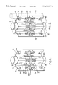
- FIG. 6 is a front view of a fragment of an outside strap belonging to the belt of the grid, showing a spring for holding a rod, which spring is of reinforced resilience and is less sensitive to accidental external stresses;
- FIGS. 7 and 8 are section views of FIG. 6 respectively along lines VII—VII and VIII—VIII;
- FIG. 9 shows a fragment of a strap including springs of the kind shown in FIG. 1 and its junction with a belt strap;
- FIG. 10 is a perspective view showing a fragment of a grid of the kind shown in FIG. 9 .
- the grid 10 is constituted in particular by two sets of crossed straps 12 and 14 that are mutually engaged via half-depth notches provided for this purpose. These straps are fixed to one another, e.g. by welding at the cross-points 16 .
- the straps 12 and 14 define cells that are to receive fuel rods 18 , such as those shown in chain-dotted lines in FIG. 2 . However, some of the cells receive guide tubes 20 designed to provide a passage for the absorbent rods of control rod clusters. In general, at least some of the guide tubes are fixed to the grids. They interconnect top and bottom fuel assembly nozzles (not shown).
- At least some of the grids of an assembly are designed to hold the rods at the nodes of a regular array and to support them vertically.
- the grid shown by way of example in FIGS. 1 and 2 performs both of these functions.
- the grid includes bearing means formed in one face of a cell and a spring cut out from the opposite face of the cell serving to press the rod against the bearing means.
- Two of the faces of each cell containing a rod have respective springs of resilience urging them to project into the cell.
- the structure of such a spring varies depending on whether it is backed by a cell that is to receive a fuel rod or a cell that contains a guide tube 20 .
- Each of the springs 22 between two cells occupied by rods is constituted by two resilient strips 24 cut out from the plane wall of the strap, and integral therewith, which strips are interconnected in their middles by a transverse bridge 26 projecting relative to the two strips.
- Each strip extends transversely to the long dimension of the strap, i.e. in the flow direction.
- Each strip 24 is connected to the strap at both ends. At rest, a strip slopes towards the inside of the cell from each end (FIG. 1 ). The bridge projects further relative to the two strips that it interconnects.
- each spring 22 lies between bearing means constituted by two bosses 28 .
- the bosses 28 and the bridges 26 may be of exactly the same shape.
- the springs and the bridges can be fabricated in conventional manner, by stamping and stretching.
- the resilient strips 24 touch each other close to their roots, and they are spaced apart from each other in their middle portions so as to leave the room required for the bridge. In this way, the gaps between the two strips which puts two adjacent cells each occupied by a rod into communication is narrow in width; it hardly disturbs the flow.
- Springs 30 backing onto a cell containing a guide tube 20 also comprise two resilient strips that are cut out from the strap and interconnected in their middle portions by a bridge 26 .
- the two strips 32 of the spring 30 extend substantially parallel to each other and to the flow direction. The gap that this establishes is not a drawback since the gap is closed by the guide tube 20 .
- the grid can be fixed to the guide tubes by spot welds, either in zones 34 that are substantially plane or slightly curved situated on either side of the springs 30 , or else on tabs formed at the top and/or bottom portions of the straps in register with the cell containing the guide tube 20 .
- the extent to which the bridges 26 project relative to the strips, and the shape of the strips at rest are advantageously selected in such a manner that the strips are forced back substantially into the same plane as the current portion of each strap when the rods 18 are in place, as can be seen in FIGS. 2, 3 , and 4 .
- the spring 22 of the strap 12 is straight and projecting because it is not being pushed back by a rod.
- the spring 22 of the left strap is bent by a rod 18 at a point such that its strips lie in practically the same plane as the common portion of the strap 20 , thereby preventing them from impeding the flow.
- the straps can be welded together not only at the cross-points 16 in each of the major faces of the grid, but also at additional locations.
- FIG. 5 shows straps 12 having pairs of additional windows 36 in alignment with each line of crossovers with other straps. This provides access making it possible to weld the straps together at two additional points at least. Welding is performed by means of a tool which is inserted into the grid, e.g. a laser beam tool.
- the windows 36 are generally situated between the bosses, level with a spring, in the flow direction.
- the grid may have four outer straps that are interconnected to form a belt. While a fuel assembly is being loaded or unloaded, there is a risk of a belt of the assembly catching on the belt of an adjacent assembly. To reduce this risk, proposals have already been made to curve the corners of the belt inwards. The risk of catching is further reduced with a belt of the kind shown in part in FIGS. 9 and 10.
- the belt-constituting outside straps have a special shape. These straps are curved inwards in their portions 40 close to their upstream edges and 42 close to their downstream edges. The ends of the common straps 12 and 14 are cut out accordingly. The upstream portion of the end of each strap 12 or 14 is rounded or chamfered and may also have a stud 44 engaged in a slot of the curved portion of the belt strap.
- each strap 12 or 14 includes a projection 46 directed in the flow direction, having rounded or chamfered edges, and against which the belt bears.
- This projection may also have a stud 44 .
- the extent to which the projection extends may be substantially equal to the extent to which the flow deflection fins 48 extend in conventional manner.
- the belt shown in FIGS. 9 and 10 may be used with common straps 12 and 14 having springs of a structure that is different from that shown in FIGS. 1 to 4 ; in particular they may be of conventional structure.
- the grid has a belt 38 in which reinforced springs are provided.
- the room for displacement of the resilient blades is restricted, and they are provided with additional protection by setting them back relative to the outside face of the grid.
- Reinforcement can be provided in particular by means of the kind shown in FIGS. 6 to 8 .
- the spring 52 is constituted by cutting out and bending a zone of the belt which is deformed inwards so as to constitute a swelling 54 .
- this swelling is of elongate shape in the flow direction, and thus in the spring direction, with parallel edges interconnected by semicircular portions.
- the swelling may also be made by stamping or by shaping in a press.
- the spring 52 itself is of conventional shape, with a projecting central portion 56 , however this shape is not essential. At rest it may project by an amount that is different from the amount by which the springs 22 and 30 project. Because of the presence of the swelling, the spring is protected against any risk of direct external attack, thereby making it possible to take full advantage of the lateral cutouts to give it optimum resilience and stiffness. Furthermore, the swelling puts a natural limit on the maximum bending of the spring by limiting the extent to which a rod can move towards the outside of the grid to a value such that the rod comes to bear thereagainst.
- the upstream edges of the straps, of the belt, of the dimples, and/or of the bridges can be shaped, for example as described in the patent application filed on the same day as the present application and entitled “A grid strap for a nuclear fuel assembly, and a grid including such straps”.
Landscapes
- Physics & Mathematics (AREA)
- Engineering & Computer Science (AREA)
- Plasma & Fusion (AREA)
- General Engineering & Computer Science (AREA)
- High Energy & Nuclear Physics (AREA)
- Fuel Cell (AREA)
- Monitoring And Testing Of Nuclear Reactors (AREA)
Abstract
Description
Claims (16)
Priority Applications (1)
| Application Number | Priority Date | Filing Date | Title |
|---|---|---|---|
| US10/358,605 US20030215049A1 (en) | 1997-07-11 | 2003-02-05 | Grid for a nuclear fuel assembly, and a strap for such a grid |
Applications Claiming Priority (3)
| Application Number | Priority Date | Filing Date | Title |
|---|---|---|---|
| FR9708873A FR2766003B1 (en) | 1997-07-11 | 1997-07-11 | GRID FOR NUCLEAR FUEL ASSEMBLY AND PLATE FOR SUCH A GRID |
| FR9708873 | 1997-07-11 | ||
| PCT/FR1998/001489 WO1999003108A1 (en) | 1997-07-11 | 1998-07-09 | Grid for nuclear fuel assembly and insert for same |
Related Child Applications (1)
| Application Number | Title | Priority Date | Filing Date |
|---|---|---|---|
| US10/358,605 Division US20030215049A1 (en) | 1997-07-11 | 2003-02-05 | Grid for a nuclear fuel assembly, and a strap for such a grid |
Publications (1)
| Publication Number | Publication Date |
|---|---|
| US6542567B1 true US6542567B1 (en) | 2003-04-01 |
Family
ID=9509159
Family Applications (2)
| Application Number | Title | Priority Date | Filing Date |
|---|---|---|---|
| US09/242,694 Expired - Lifetime US6542567B1 (en) | 1997-07-11 | 1998-07-09 | Grid for nuclear fuel assembly and a strap for such a grid |
| US10/358,605 Abandoned US20030215049A1 (en) | 1997-07-11 | 2003-02-05 | Grid for a nuclear fuel assembly, and a strap for such a grid |
Family Applications After (1)
| Application Number | Title | Priority Date | Filing Date |
|---|---|---|---|
| US10/358,605 Abandoned US20030215049A1 (en) | 1997-07-11 | 2003-02-05 | Grid for a nuclear fuel assembly, and a strap for such a grid |
Country Status (12)
| Country | Link |
|---|---|
| US (2) | US6542567B1 (en) |
| EP (2) | EP0925589B1 (en) |
| JP (1) | JP3989972B2 (en) |
| KR (1) | KR100657603B1 (en) |
| CN (1) | CN1173368C (en) |
| DE (1) | DE69818410T2 (en) |
| ES (1) | ES2209173T3 (en) |
| FR (1) | FR2766003B1 (en) |
| RU (1) | RU2173485C2 (en) |
| TW (1) | TW434572B (en) |
| WO (1) | WO1999003108A1 (en) |
| ZA (1) | ZA986070B (en) |
Cited By (15)
| Publication number | Priority date | Publication date | Assignee | Title |
|---|---|---|---|---|
| US20050105677A1 (en) * | 2003-10-07 | 2005-05-19 | Kyung-Ho Yoon | Spacer grid for nuclear reactor fuel assemblies |
| US20070223646A1 (en) * | 2006-03-27 | 2007-09-27 | Westinghouse Electric Company Llc | Bi-alloy spacer grid and associated methods |
| FR2920586A1 (en) * | 2007-08-27 | 2009-03-06 | Korea Nuclear Fuel Co Ltd | Anti-abrasive wear spacer grid for nuclear fuel rods in nuclear reactor, has tabs each applying elastic force on canoe-shaped spring and connecting sides of tab connection part such that connection part is projected to preset height |
| US20110200160A1 (en) * | 2010-02-16 | 2011-08-18 | Westinghouse Electric Company | Split spring anti-fretting fuel rod support structure |
| US8116423B2 (en) | 2007-12-26 | 2012-02-14 | Thorium Power, Inc. | Nuclear reactor (alternatives), fuel assembly of seed-blanket subassemblies for nuclear reactor (alternatives), and fuel element for fuel assembly |
| US20130230133A1 (en) * | 2012-03-02 | 2013-09-05 | China Guangdong Nuclear Power Holding | Advanced grid spacer design for a nuclear fuel assembly |
| US8654917B2 (en) | 2007-12-26 | 2014-02-18 | Thorium Power, Inc. | Nuclear reactor (alternatives), fuel assembly of seed-blanket subassemblies for nuclear reactor (alternatives), and fuel element for fuel assembly |
| US9171647B2 (en) | 2012-08-06 | 2015-10-27 | Kepco Nuclear Fuel Co., Ltd. | Spacer grid for nuclear fuel assembly for reducing flow-induced vibration |
| US9355747B2 (en) | 2008-12-25 | 2016-05-31 | Thorium Power, Inc. | Light-water reactor fuel assembly (alternatives), a light-water reactor, and a fuel element of fuel assembly |
| US9378852B2 (en) | 2012-04-17 | 2016-06-28 | Bwxt Mpower, Inc. | Spacer grids for nuclear reactor |
| US9881701B2 (en) | 2012-04-17 | 2018-01-30 | Bwxt Mpower, Inc. | Spacer grids with springs having improved robustness |
| US10037823B2 (en) | 2010-05-11 | 2018-07-31 | Thorium Power, Inc. | Fuel assembly |
| US10170207B2 (en) | 2013-05-10 | 2019-01-01 | Thorium Power, Inc. | Fuel assembly |
| US10192644B2 (en) | 2010-05-11 | 2019-01-29 | Lightbridge Corporation | Fuel assembly |
| US10672521B2 (en) | 2012-03-23 | 2020-06-02 | Global Nuclear Fuel—Americas, LLC | Spacers with deflection-limited peripheral springs for nuclear fuel assemblies and methods of making the same |
Families Citing this family (14)
| Publication number | Priority date | Publication date | Assignee | Title |
|---|---|---|---|---|
| FR2802330B1 (en) * | 1999-12-13 | 2002-03-01 | Franco Belge Combustibles | DEVICE AND METHOD FOR MOUNTING A GRID SPACER OF A FUEL ASSEMBLY FOR A NUCLEAR REACTOR |
| KR100432581B1 (en) * | 2001-07-10 | 2004-05-24 | 한국수력원자력 주식회사 | Spacer Grid for Uniform Conformal Contact with Fuel Rod and for Extending the Elastic Range of the Grid Spring |
| KR100444699B1 (en) * | 2001-12-26 | 2004-08-21 | 한국수력원자력 주식회사 | lips-type multi-purposed nuclear fuel assembly spacer grid |
| US6606369B1 (en) | 2002-03-06 | 2003-08-12 | Westinghouse Electric Company Llc | Nuclear reactor with improved grid |
| US6819733B2 (en) * | 2002-05-15 | 2004-11-16 | Westinghouse Electric Company Llc | Fuel assembly and associated grid for nuclear reactor |
| FR2878645B1 (en) * | 2004-11-30 | 2007-02-09 | Framatome Anp Sas | PEN HOLDING GRID FOR NUCLEAR FUEL ASSEMBLY AND CORRESPONDING ASSEMBLY |
| RU2322710C2 (en) * | 2006-05-02 | 2008-04-20 | Открытое акционерное общество "Новосибирский завод химконценратов" | Method for producing spacer grids for nuclear reactor fuel assembly |
| US9053827B2 (en) * | 2009-03-27 | 2015-06-09 | Westinghouse Electric Company Llc | Nuclear fuel assembly with pivot dimpled grids |
| EP2525366A1 (en) | 2011-05-20 | 2012-11-21 | Areva NP | Strip for a nuclear fuel assembly spacer grid |
| US10311982B2 (en) * | 2016-02-17 | 2019-06-04 | Westinghouse Electric Company Llc | Holding fixture to assist in assembly of support grid for nuclear fuel rods and method for assembling support grid for nuclear fuel rods |
| CN107221358A (en) * | 2017-06-09 | 2017-09-29 | 中广核研究院有限公司 | A kind of nuclear fuel assembly, location grid and spring |
| EP4016547A1 (en) * | 2020-12-21 | 2022-06-22 | Framatome | Spacer grid element of a nuclear fuel assembly spacer grid, spacer grids and nuclear fuel assembly |
| CN113362973B (en) * | 2021-06-04 | 2022-02-22 | 中国核动力研究设计院 | Grid spring for improving abrasion resistance and reducing resistance and positioning grid |
| CN115351207B (en) * | 2022-08-12 | 2025-07-25 | 成都纽安能杰自动化科技有限公司 | Control method of strip spring production line equipment |
Citations (12)
| Publication number | Priority date | Publication date | Assignee | Title |
|---|---|---|---|---|
| US3769159A (en) * | 1968-06-24 | 1973-10-30 | Combustion Eng | Fuel element grid support for nuclear reactor |
| US3789184A (en) * | 1969-12-23 | 1974-01-29 | Reactor Centrum Nederland | Air-excluding spot-welding method for making heat-exchange grid |
| FR2338549A1 (en) | 1976-01-14 | 1977-08-12 | Commissariat Energie Atomique | Spacing grid for nuclear reactor combustible assembly - has spring holders, and slots in grid increasing holder flexibility |
| US4224107A (en) * | 1978-05-09 | 1980-09-23 | Commissariat A L'energie Atomique | Spacer grids for a nuclear reactor fuel assembly |
| EP0025395A1 (en) | 1979-09-07 | 1981-03-18 | COMMISSARIAT A L'ENERGIE ATOMIQUE Etablissement de Caractère Scientifique Technique et Industriel | Spacer grid for nuclear fuel elements |
| EP0196598A1 (en) | 1985-04-02 | 1986-10-08 | Westinghouse Electric Corporation | Spacer grid of a nuclear reactor fuel assembly |
| US5139736A (en) | 1991-04-03 | 1992-08-18 | Combustion Engineering, Inc. | Fuel assembly support grid |
| US5331678A (en) | 1993-04-27 | 1994-07-19 | Combustion Engineering, Inc. | Spacer grid rod support system |
| US5444748A (en) * | 1994-04-04 | 1995-08-22 | Westinghouse Electric Corporation | Grid structure for supporting fuel rods in a nuclear reactor |
| US5515408A (en) * | 1993-12-03 | 1996-05-07 | Mitsubishi Nuclear Fuel Co. | Fuel assembly |
| US5577081A (en) * | 1994-07-21 | 1996-11-19 | Mitsubishi Nuclear Fuel Co. | Method of forming grids for nuclear fuel assembly and grids formed by same method |
| US5638416A (en) * | 1993-12-03 | 1997-06-10 | Mitsubishi Nuclear Fuel Co. | Fuel assembly |
Family Cites Families (11)
| Publication number | Priority date | Publication date | Assignee | Title |
|---|---|---|---|---|
| US4039379A (en) * | 1975-02-28 | 1977-08-02 | Exxon Nuclear Company, Inc. | Mixing vane grid spacer |
| SE456705B (en) * | 1983-03-09 | 1988-10-24 | Westinghouse Electric Corp | GALLER BEFORE HAVING BRAENLET STARS IN A BRAEN CARTRIDGE IN A NUCLEAR REACTOR |
| FR2608827B1 (en) * | 1986-04-02 | 1990-06-15 | Framatome Sa | SPACING GRILLE FOR NUCLEAR FUEL ASSEMBLY |
| US4756878A (en) * | 1986-12-01 | 1988-07-12 | Advanced Nuclear Fuels Corporation | Grid spacer and method of making same |
| FR2665292B1 (en) * | 1990-07-24 | 1992-11-13 | Framatome Sa | ADDITIONAL GRILLE FOR FUEL ASSEMBLY OF NUCLEAR REACTOR AND ASSEMBLY COMPRISING APPLICATION. |
| US5188797A (en) * | 1991-04-03 | 1993-02-23 | Combustion Engineering, Inc. | Extended weld tab for fuel assembly grid |
| ES2078398T3 (en) * | 1991-08-05 | 1995-12-16 | Siemens Ag | SPACER FOR COMBUSTIBLE ELEMENTS WITH OVERLAPPED CURVED SPRINGS. |
| JPH0627275A (en) * | 1992-07-10 | 1994-02-04 | Mitsubishi Nuclear Fuel Co Ltd | Supporting grid of fuel assembly |
| FR2697368B1 (en) * | 1992-10-28 | 1995-01-13 | Framatome Sa | Grid-spacer of a fuel assembly of a nuclear reactor cooled by light water. |
| RU2081461C1 (en) * | 1993-08-24 | 1997-06-10 | Пугачев Геннадий Федорович | Spacing lattice of heat-emitting assembly of nuclear reactor |
| FR2736190B1 (en) * | 1995-06-29 | 1997-10-10 | Framatome Sa | GRID SPACER OF A FUEL ASSEMBLY FOR A NUCLEAR REACTOR AND FUEL ASSEMBLY |
-
1997
- 1997-07-11 FR FR9708873A patent/FR2766003B1/en not_active Expired - Fee Related
-
1998
- 1998-07-08 TW TW087111027A patent/TW434572B/en not_active IP Right Cessation
- 1998-07-09 ES ES98937598T patent/ES2209173T3/en not_active Expired - Lifetime
- 1998-07-09 WO PCT/FR1998/001489 patent/WO1999003108A1/en not_active Ceased
- 1998-07-09 CN CNB988009536A patent/CN1173368C/en not_active Expired - Fee Related
- 1998-07-09 RU RU99104816/06A patent/RU2173485C2/en not_active IP Right Cessation
- 1998-07-09 KR KR1019997002024A patent/KR100657603B1/en not_active Expired - Fee Related
- 1998-07-09 ZA ZA9806070A patent/ZA986070B/en unknown
- 1998-07-09 EP EP98937598A patent/EP0925589B1/en not_active Expired - Lifetime
- 1998-07-09 EP EP03013994A patent/EP1367600A1/en not_active Withdrawn
- 1998-07-09 DE DE69818410T patent/DE69818410T2/en not_active Expired - Lifetime
- 1998-07-09 US US09/242,694 patent/US6542567B1/en not_active Expired - Lifetime
- 1998-07-09 JP JP50827199A patent/JP3989972B2/en not_active Expired - Fee Related
-
2003
- 2003-02-05 US US10/358,605 patent/US20030215049A1/en not_active Abandoned
Patent Citations (14)
| Publication number | Priority date | Publication date | Assignee | Title |
|---|---|---|---|---|
| US3769159A (en) * | 1968-06-24 | 1973-10-30 | Combustion Eng | Fuel element grid support for nuclear reactor |
| US3789184A (en) * | 1969-12-23 | 1974-01-29 | Reactor Centrum Nederland | Air-excluding spot-welding method for making heat-exchange grid |
| FR2338549A1 (en) | 1976-01-14 | 1977-08-12 | Commissariat Energie Atomique | Spacing grid for nuclear reactor combustible assembly - has spring holders, and slots in grid increasing holder flexibility |
| US4224107A (en) * | 1978-05-09 | 1980-09-23 | Commissariat A L'energie Atomique | Spacer grids for a nuclear reactor fuel assembly |
| EP0025395A1 (en) | 1979-09-07 | 1981-03-18 | COMMISSARIAT A L'ENERGIE ATOMIQUE Etablissement de Caractère Scientifique Technique et Industriel | Spacer grid for nuclear fuel elements |
| US4396573A (en) * | 1979-09-07 | 1983-08-02 | Commissariat A L'energie Atomique | Space grate for fuel-elements of nuclear reactors |
| EP0196598A1 (en) | 1985-04-02 | 1986-10-08 | Westinghouse Electric Corporation | Spacer grid of a nuclear reactor fuel assembly |
| US4702881A (en) * | 1985-04-02 | 1987-10-27 | Westinghouse Electric Corp. | Nuclear reactor spacer grid |
| US5139736A (en) | 1991-04-03 | 1992-08-18 | Combustion Engineering, Inc. | Fuel assembly support grid |
| US5331678A (en) | 1993-04-27 | 1994-07-19 | Combustion Engineering, Inc. | Spacer grid rod support system |
| US5515408A (en) * | 1993-12-03 | 1996-05-07 | Mitsubishi Nuclear Fuel Co. | Fuel assembly |
| US5638416A (en) * | 1993-12-03 | 1997-06-10 | Mitsubishi Nuclear Fuel Co. | Fuel assembly |
| US5444748A (en) * | 1994-04-04 | 1995-08-22 | Westinghouse Electric Corporation | Grid structure for supporting fuel rods in a nuclear reactor |
| US5577081A (en) * | 1994-07-21 | 1996-11-19 | Mitsubishi Nuclear Fuel Co. | Method of forming grids for nuclear fuel assembly and grids formed by same method |
Cited By (25)
| Publication number | Priority date | Publication date | Assignee | Title |
|---|---|---|---|---|
| US7769125B2 (en) * | 2003-10-07 | 2010-08-03 | Korea Atomic Energy Research Institute | Spacer grid for nuclear reactor fuel assemblies |
| US20050105677A1 (en) * | 2003-10-07 | 2005-05-19 | Kyung-Ho Yoon | Spacer grid for nuclear reactor fuel assemblies |
| US20070223646A1 (en) * | 2006-03-27 | 2007-09-27 | Westinghouse Electric Company Llc | Bi-alloy spacer grid and associated methods |
| US7623612B2 (en) * | 2006-03-27 | 2009-11-24 | Westinghouse Electric Co. Llc | Bi-alloy spacer grid and associated methods |
| FR2920586A1 (en) * | 2007-08-27 | 2009-03-06 | Korea Nuclear Fuel Co Ltd | Anti-abrasive wear spacer grid for nuclear fuel rods in nuclear reactor, has tabs each applying elastic force on canoe-shaped spring and connecting sides of tab connection part such that connection part is projected to preset height |
| US20100098208A1 (en) * | 2007-08-27 | 2010-04-22 | Korea Nuclear Fuel Co., Ltd. | Anti-fretting Wear Spacer Grid With Canoe-Shaped Spring |
| US7835484B2 (en) * | 2007-08-27 | 2010-11-16 | Korea Nuclear Fuel Co., Ltd | Anti-fretting wear spacer grid with canoe-shaped spring |
| US8654917B2 (en) | 2007-12-26 | 2014-02-18 | Thorium Power, Inc. | Nuclear reactor (alternatives), fuel assembly of seed-blanket subassemblies for nuclear reactor (alternatives), and fuel element for fuel assembly |
| US8116423B2 (en) | 2007-12-26 | 2012-02-14 | Thorium Power, Inc. | Nuclear reactor (alternatives), fuel assembly of seed-blanket subassemblies for nuclear reactor (alternatives), and fuel element for fuel assembly |
| US9355747B2 (en) | 2008-12-25 | 2016-05-31 | Thorium Power, Inc. | Light-water reactor fuel assembly (alternatives), a light-water reactor, and a fuel element of fuel assembly |
| US20110200160A1 (en) * | 2010-02-16 | 2011-08-18 | Westinghouse Electric Company | Split spring anti-fretting fuel rod support structure |
| US11862353B2 (en) | 2010-05-11 | 2024-01-02 | Thorium Power, Inc. | Fuel assembly |
| US11837371B2 (en) | 2010-05-11 | 2023-12-05 | Thorium Power, Inc. | Method of manufacturing a nuclear fuel assembly |
| US11195629B2 (en) | 2010-05-11 | 2021-12-07 | Thorium Power, Inc. | Fuel assembly |
| US10037823B2 (en) | 2010-05-11 | 2018-07-31 | Thorium Power, Inc. | Fuel assembly |
| US10991473B2 (en) | 2010-05-11 | 2021-04-27 | Thorium Power, Inc. | Method of manufacturing a nuclear fuel assembly |
| US10192644B2 (en) | 2010-05-11 | 2019-01-29 | Lightbridge Corporation | Fuel assembly |
| US20130230133A1 (en) * | 2012-03-02 | 2013-09-05 | China Guangdong Nuclear Power Holding | Advanced grid spacer design for a nuclear fuel assembly |
| US9767929B2 (en) * | 2012-03-02 | 2017-09-19 | China Nuclear Power Technology Research Institute | Advanced grid spacer design for a nuclear fuel assembly |
| US10672521B2 (en) | 2012-03-23 | 2020-06-02 | Global Nuclear Fuel—Americas, LLC | Spacers with deflection-limited peripheral springs for nuclear fuel assemblies and methods of making the same |
| US9881701B2 (en) | 2012-04-17 | 2018-01-30 | Bwxt Mpower, Inc. | Spacer grids with springs having improved robustness |
| US9378852B2 (en) | 2012-04-17 | 2016-06-28 | Bwxt Mpower, Inc. | Spacer grids for nuclear reactor |
| US9171647B2 (en) | 2012-08-06 | 2015-10-27 | Kepco Nuclear Fuel Co., Ltd. | Spacer grid for nuclear fuel assembly for reducing flow-induced vibration |
| US10170207B2 (en) | 2013-05-10 | 2019-01-01 | Thorium Power, Inc. | Fuel assembly |
| US11211174B2 (en) | 2013-05-10 | 2021-12-28 | Thorium Power, Inc. | Fuel assembly |
Also Published As
| Publication number | Publication date |
|---|---|
| ZA986070B (en) | 2000-01-10 |
| ES2209173T3 (en) | 2004-06-16 |
| EP1367600A1 (en) | 2003-12-03 |
| EP0925589B1 (en) | 2003-09-24 |
| WO1999003108A1 (en) | 1999-01-21 |
| CN1231053A (en) | 1999-10-06 |
| FR2766003A1 (en) | 1999-01-15 |
| DE69818410D1 (en) | 2003-10-30 |
| CN1173368C (en) | 2004-10-27 |
| FR2766003B1 (en) | 1999-12-03 |
| RU2173485C2 (en) | 2001-09-10 |
| JP3989972B2 (en) | 2007-10-10 |
| KR100657603B1 (en) | 2006-12-14 |
| EP0925589A1 (en) | 1999-06-30 |
| DE69818410T2 (en) | 2004-05-06 |
| TW434572B (en) | 2001-05-16 |
| US20030215049A1 (en) | 2003-11-20 |
| JP2001500273A (en) | 2001-01-09 |
| KR20000068536A (en) | 2000-11-25 |
Similar Documents
| Publication | Publication Date | Title |
|---|---|---|
| US6542567B1 (en) | Grid for nuclear fuel assembly and a strap for such a grid | |
| EP0514120B1 (en) | Swirl vanes in inconel spacer | |
| US6421407B1 (en) | Nuclear fuel spacer grid with dipper vanes | |
| KR100265027B1 (en) | Nozzle type mixing grid of nuclear fuel assembly | |
| US5440599A (en) | Spacer grid with integral "side supported" flow directing vanes | |
| JP3605171B2 (en) | Reactor fuel assembly | |
| US4585616A (en) | Nuclear fuel spacer grid with improved outer straps | |
| US5139736A (en) | Fuel assembly support grid | |
| EP0148452B1 (en) | A coolant flow mixing grid for a nuclear reactor fuel assembly | |
| US6650723B1 (en) | Double strip mixing grid for nuclear reactor fuel assemblies | |
| EP1416500B1 (en) | Side-slotted nozzle type double sheet spacer grid for nuclear fuel assemblies | |
| JPH05196768A (en) | Fuel assembly grid spacers | |
| EP0722172A1 (en) | Spacer for fuel rods | |
| US5875223A (en) | Spacer for a nuclear fuel assembly and a nuclear fuel assembly | |
| KR102939021B1 (en) | Nuclear fuel assembly with reinforcement device | |
| US4951299A (en) | Intermediate mixing grid | |
| US5174950A (en) | Grid for nuclear fuel assembly | |
| US6332012B1 (en) | Grid strap for a nuclear fuel assembly, and a grid including such straps | |
| US5757874A (en) | Multi-spring strip spacer for nuclear fuel bundles | |
| GB2060981A (en) | Spacer grid | |
| US6320925B1 (en) | Space for a fuel assembly of a nuclear power station | |
| SK20094A3 (en) | Distance lattice for nuclear fuel elements | |
| SK121696A3 (en) | Spacer with hexagonal interstices | |
| Patterson et al. | Nuclear reactor spring strip grid spacer | |
| JPH0511874B2 (en) |
Legal Events
| Date | Code | Title | Description |
|---|---|---|---|
| AS | Assignment |
Owner name: COMPAGNIE GENERALE DES MATIERES NUCLEAIRES, FRANCE Free format text: ASSIGNMENT OF ASSIGNORS INTEREST;ASSIGNORS:MAYET, ROLAND;BONNAMOUR, MICHEL;REEL/FRAME:010051/0174 Effective date: 19990204 Owner name: FRAMATOME, FRANCE Free format text: ASSIGNMENT OF ASSIGNORS INTEREST;ASSIGNORS:MAYET, ROLAND;BONNAMOUR, MICHEL;REEL/FRAME:010051/0174 Effective date: 19990204 |
|
| AS | Assignment |
Owner name: FRAMATOME, FRANCE Free format text: ASSIGNMENT OF ASSIGNORS INTEREST;ASSIGNOR:COMPAGNIE GENERALE DES MATIERES NUCLEAIRES;REEL/FRAME:012364/0662 Effective date: 20010703 |
|
| STCF | Information on status: patent grant |
Free format text: PATENTED CASE |
|
| AS | Assignment |
Owner name: FRAMATOME ANP, FRANCE Free format text: ASSIGNMENT OF ASSIGNORS INTEREST;ASSIGNOR:FRAMATOME;REEL/FRAME:014249/0032 Effective date: 20010901 |
|
| FEPP | Fee payment procedure |
Free format text: PAYOR NUMBER ASSIGNED (ORIGINAL EVENT CODE: ASPN); ENTITY STATUS OF PATENT OWNER: LARGE ENTITY |
|
| FPAY | Fee payment |
Year of fee payment: 4 |
|
| FPAY | Fee payment |
Year of fee payment: 8 |
|
| FPAY | Fee payment |
Year of fee payment: 12 |