US6539255B1 - Full-tilt exponential defibrillation waveform - Google Patents
Full-tilt exponential defibrillation waveform Download PDFInfo
- Publication number
- US6539255B1 US6539255B1 US09/354,300 US35430099A US6539255B1 US 6539255 B1 US6539255 B1 US 6539255B1 US 35430099 A US35430099 A US 35430099A US 6539255 B1 US6539255 B1 US 6539255B1
- Authority
- US
- United States
- Prior art keywords
- pulse
- defibrillator
- waveform
- energy
- full
- Prior art date
- Legal status (The legal status is an assumption and is not a legal conclusion. Google has not performed a legal analysis and makes no representation as to the accuracy of the status listed.)
- Expired - Fee Related
Links
Images


Classifications
-
- A—HUMAN NECESSITIES
- A61—MEDICAL OR VETERINARY SCIENCE; HYGIENE
- A61N—ELECTROTHERAPY; MAGNETOTHERAPY; RADIATION THERAPY; ULTRASOUND THERAPY
- A61N1/00—Electrotherapy; Circuits therefor
- A61N1/18—Applying electric currents by contact electrodes
- A61N1/32—Applying electric currents by contact electrodes alternating or intermittent currents
- A61N1/38—Applying electric currents by contact electrodes alternating or intermittent currents for producing shock effects
- A61N1/39—Heart defibrillators
- A61N1/3906—Heart defibrillators characterised by the form of the shockwave
- A61N1/3912—Output circuitry therefor, e.g. switches
Definitions
- the present invention relates to internal and external defibrillation pulses and, more particularly, to exponentially decaying defibrillation pulse waveforms that do not utilize truncation.
- Implantable defibrillators are well accepted by the medical community as effective tools to combat ventricular fibrillation for an identified segment of the population. A substantial amount of research in fibrillation and the therapy of defibrillation has been done. Much of the most recent research has concentrated on understanding the effects that a defibrillation shock pulse has on fibrillation and the ability to terminate such a condition.
- defibrillation shock pulses are delivered through use of a monophasic waveform or, alternatively, a biphasic waveform.
- a monophasic waveform is typically a single phase, capacitive-discharge, time-truncated, waveform with exponential decay.
- a biphasic waveform is defined to comprise two monophasic waveforms that are separated by time and that are of opposite polarity. The first phase is designated ⁇ 1 and the second phase is designated ⁇ 2 . The delivery of ⁇ 1 is completed before the delivery of ⁇ 2 is begun.
- biphasic waveforms are more efficacious than monophasic waveforms.
- ⁇ 1 defibrillates the heart and ⁇ 2 performs a stabilizing action that keeps the heart from refibrillating.
- Biphasic defibrillation waveforms are now the standard of care in clinical user for defibrillation with implantable cardioverter-defibrillators (ICDs), due to the superior performance demonstrated over that of comparable monophasic waveforms.
- ICD research has developed cardiac cell response models. Waveform design criteria have been derived from these models and have been applied to monophasic and biphasic waveforms to optimize their parameters. These model-based design criteria have produced significant improvements over previously used waveforms.
- Kroll developed a biphasic model for the optimal design of ⁇ 2 for a biphasic defibrillation waveform as applied internally.
- Kroll, M. W. “A Minimal Model of the Single Capacitor Biphasic Defibrillation Waveform.” PACE 1994; 17:1782-1792.
- Kroll supported his hypothesis with retrospective analysis of studies by Dixon, et al., Tang, et al., and Freese, et al., regarding single capacitor, biphasic waveform studies.
- the “charge burping” hypothesis may be used to develop equations that describe the time course of a cell's membrane potential during a biphasic shock pulse. At the end of ⁇ 1 , those cells that were not stimulated by ⁇ 1 have a residual charge due to the action of ⁇ 1 , on the cell.
- the “charge burping” model hypothesizes that an optimal duration for ⁇ 2 is that duration which removes as much of the ⁇ 1 residual charge from the cell as possible. Ideally, these unstimulated cells are set back to “relative ground.”
- the “charge burping” model proposed by Kroll is based on the circuit model shown in FIG. 1B, which is adapted from the general model of a defibrillator in FIG. 1 A. in FIG.
- R H represents the resistance of the heart
- the pair C M and R M represent membrane series capacitance and resistance of a single cell.
- C 1 represents the ⁇ 1 and ⁇ 2 capacitor set.
- the node V S represents the voltage between the internal electrodes, while V M denotes the voltage across the cell membrane.
- charge burping model may also account for removing residual cell membrane potential at the end of a ⁇ 1 that is independent of a ⁇ 2 pulse, i.e., ⁇ 2 is delivered by a set of capacitors separate from the set of capacitors used to deliver ⁇ 1 .
- This “charge burping” model is constructed by adding a second set of capacitors, as illustrated in FIG. 2 .
- C 2 represents the ⁇ 2 capacitor set that is separate from C 1 .
- external defibrillators can not deliver electrical shock pulses directly to the heart. Rather, external defibrillators must send electrical pulses to the patient's heart through electrodes that are applied to the patient's torso. External defibrillators are useful in any situation where there may be an unanticipated need to provide electrotherapy to a patient on short notice.
- the advantage of external defibrillators is that they may be used on a patient as needed, then subsequently moved to be used on another patient.
- Kroll, Walcott, Cleland, and others developed the passive cardiac cell membrane response model for monophasic and biphasic waveforms, herein called the cell response model.
- Kroll, M. W. “A Minimal Model of the Single Capacitor Biphasic Waveform.” PACE 1994: 17:1782.
- Walcott, G. P., Walker, R. G. Cates, A. W., Krassowska, W., Smith, W. M., Ideker, R. E., “Choosing the Optimal Monophasic and Biphasic Waveforms for Ventricular Defibrillation.” J. Cardiovasc. Electrophysio. 1995; 6:737.
- Cleland, B. G. “A Conceptual Basis for Defibrillation Waveforms.” PACE 1996; 19:1186.
- Block et al. has recently written a comprehensive survey of the new principles-based theories and their impact on optimizing internal defibrillation through improved waveforms.
- a circuit that delivers a truncated exponential waveform uses switching mechanisms or relays to cut off, or truncate, the waveform. These switching mechanisms truncate the waveform during the time that the defibrillation pulse is being delivered and at a time when there is still a great amount of current flowing through the switching mechanism. Because of the great current, the switching mechanisms are subjected to extreme wear and are prone to failure. Attempting to respond to these failures, U.S. Pat. No. 5,748,427 discloses a method and system for detecting switching mechanism failure in external defibrillators.
- U.S. Pat. No. 5,405,361 discloses a multiple switching external defibrillator. Whether introducing special design considerations in the form of failure detection or multiple switches, additional time, money and effort are expended.
- the needs described above are in large measure met by a full-tilt exponential defibrillation pulse waveform of the present invention.
- the characteristics of the full-tilt exponential waveform are developed through use of a charge burping model or through use of a transthoracic cell response model. These characteristics are implemented within a pulse delivery circuit, which itself is implemented within an internal defibrillator or within an external defibrillator.
- the pulse delivery circuit includes at least one switch which starts and stops the delivery of the defibrillation pulse. Delivery of the defibrillation pulse is started by the switch when there is sufficient stored energy to deliver a desired pulse. Delivery of the defibrillation pulse is stopped by the switch when the current flowing through the switch is substantially zero and the exponential waveform of the pulse is substantially fully decayed.
- FIG. 1A depicts a prior art, general circuit model of an internal defibrillator.
- FIG. 1B depicts a prior art expanded circuit model of an internal defibrillator.
- FIG. 2 depicts a prior art expanded circuit model of an internal defibrillator including two capacitor sets.
- FIG. 3 depicts a transthoracic cell response circuit model.
- FIG. 4A depicts an alternative embodiment of the transthoracic cell response circuit model of FIG. 3 .
- FIG. 4B depicts another alternative embodiment of the transthoracic cell response circuit model of FIG. 3 .
- FIG. 5 depicts a block diagram of a pulse delivery circuit.
- FIG. 6 depicts a block diagram of a voltage monitoring circuit that is incorporated with the pulse deliver circuit of FIG. 5 .
- FIG. 7 depicts a biphasic full-tilt exponential waveform.
- FIG. 8 depicts a prior art truncated exponential waveform.
- FIG. 9A depicts an automatic external defibrillator with a closed lid.
- FIG. 9B depicts an automatic external defibrillator with an open lid.
- the characteristics of a full-tilt exponential waveform are designed by using the charge burping model of the prior art (internal defibrillation) or by using a transthoracic cell response model (external defibrillation) as described herein.
- the characteristics of the full-tilt exponential waveform are then implemented within a pulse delivery circuit as described herein. That pulse delivery circuit is then preferably implemented within an internal or external defibrillator, a basic description of each of which is described herein.
- the characteristics of a full-tilt exponential waveform for internal defibrillation are preferably developed through the use of the charge burping model, as referenced in the “Background of the Invention” above, and its associated design criteria.
- the characteristic of a full-tilt exponential waveform for external defibrillation are preferably developed through the use a transthoracic cell response model 10 as depicted in FIG. 3 .
- Transthoracic defibrillation is generally performed by placing electrodes on the apex and anterior positions of the chest wall. With this electrode arrangement, the main series pathway for current is to pass through the chest wall, the lungs, and on to the heart. Additionally, there are two shunting pathways in parallel with the current pathway to the heart. The first shunting, parallel pathway is created by the lungs shunting current around the heart and the second is created by the thoracic cage. However, it should be noted that the resistivity of the thoracic cage (and the skeletal muscle structure) is low compared to the resistance provided by the lungs.
- the high resistivity of the lungs and the resistivity of the shunting pathways are characteristic elements of external defibrillation which help to distinguish external defibrillation from internal, e.g., intracardiac and implantable, defibrillation.
- transthoracic cell response model 10 which is an expansion of the original “charge burping” model of FIGS. 1A, 1 B and 2 .
- transthoracic cell response model 10 includes the following elements: (1) R S which represents the resistance of the defibrillation system, including the resistance of the electrodes; (2) R CW and R LS which represent the resistance of the chest wall and lungs, respectively, in series with the resistance of the heart, R H ; (3) R TC and R LP which represent the resistance of the thoracic cage and the lungs, respectively, in parallel with the resistance of the heart, R H ; and, (4) the elements from the original “charge burping” model, including R M which represents the resistance of a single cell membrane in series with C M which represents the capacitance of the cell membrane.
- Capacitors C 1 and C 2 are the charging capacitor sets for the delivery of a first waveform of a biphasic waveform, ⁇ 1 , and for the delivery of a second waveform of a biphasic waveform, ⁇ 2 , respectively.
- FIGS. 4A and 4B depict alternative embodiments of transthoracic cell response model 10 of FIG. 3 .
- each circuit additionally incorporates an inductor in series with each charging capacitor, e.g., L 1 in series with C 1 in FIG. 4A and L 1 in series with C 1 and L 2 in series with C 2 in FIG. 4 B.
- the inductors act to produce a shock pulse that is in the form of a damped sine wave.
- FIG. 4A represents a monophasic external defibrillator while FIG. 4B represents a biphasic external defibrillator.
- transchest transfer function is defined as the voltage that is applied across each myocardial cell during an external defibrillation shock and is indicated on transthoracic cell response model 10 as V 3 .
- V 1 V S R S ⁇ ⁇ 1 + V 2 R CW ⁇ ⁇ 1 Eq. (4B)
- V 2 V S R S ⁇ R CW ⁇ ⁇ 1 ⁇ ⁇ 2 ⁇ ⁇ 22 + V 3 R LS ⁇ ⁇ 2 ⁇ ⁇ 22 Eq. (5)
- ⁇ 2 1 R LS + 1 R LP + 1 R CW ;
- ⁇ 22 1 - 1 R CW 2 ⁇ ⁇ 1 ⁇ ⁇ 2
- V 3 V 2 R LS ⁇ ⁇ 3 + V M R M ⁇ ⁇ 3 Eq. (7)
- V 3 V S R S ⁇ R CW ⁇ R LS ⁇ ⁇ 1 ⁇ ⁇ 2 ⁇ ⁇ 22 ⁇ ⁇ 3 ⁇ ⁇ 33 + V M R M ⁇ ⁇ 3 ⁇ ⁇ 33 Eq. (8)
- V 3 V S ⁇ S + V M ⁇ M Eq. (14)
- V 3 is the general transchest transfer function for transthoracic cell response model 10 of FIG. 3, and applies equally as well to the alternative transthoracic cell response models 10 of FIGS. 4A and 4B.
- Equation 14 encapsulates the transchest elements and their association between a forcing function, V S (which models a defibrillation circuit and a shock pulse) and a myocardial cell membrane voltage, V M .
- the design equations for a monophasic waveform (or the first waveform of a biphasic waveform) ⁇ 1 may be determined.
- the design equations describe: (1) a cell's response transchest transfer function; (2) the optimal pulse duration of ⁇ 1 , and (3) the optimal capacitor for delivering ⁇ 1 .
- a cell's response transchest transfer function For a cell's response transchest transfer function; (2) the optimal pulse duration of ⁇ 1 , and (3) the optimal capacitor for delivering ⁇ 1 .
- forcing function V S is preferably replaced with a more specific description of the defibrillation circuitry that implements the shock pulse.
- V 1 is the leading-edge voltage for the shock pulse, i.e., the initial C 1 capacitor voltage, and ⁇ 1 RC 1
- Equation 21 is now in the form of a general ordinary differential equation (ODE) that models the effects of any forcing function V S that represents a phase of a shock pulse waveform applied across the chest. More specifically, ODE Equation 21 models the effects of a general shock pulse phase V S on the myocardium, allowing one to determine cardiac cell response to the shock pulse phase.
- ODE general ordinary differential equation
- Equation 23 The generic solution to Equation 23 is as follows:
- V M1 ⁇ ( t ) k ⁇ ⁇ ⁇ - ( t ⁇ M ) ⁇ ( 1 - 1 ⁇ M ) + ( V 1 ⁇ S ) ⁇ ( ⁇ 1 ⁇ 1 ⁇ ( 1 - 1 ⁇ M ) - ⁇ M ) ⁇ ⁇ - t ⁇ 1 Eq . ⁇ ( 25 )
- Equation 25 is an expression of myocardial cell membrane potential during ⁇ 1 of a shock pulse.
- k V G - ( V 1 ⁇ S ) ⁇ ( ⁇ 1 ⁇ 1 ⁇ ( 1 - 1 ⁇ M ) - ⁇ M ) Eq . ⁇ ( 26 )
- R S represents the resistance of the defibrillation system including the electrodes
- R B represents the body impedance, e.g., thoracic cage, chest wall, lungs (series, parallel), and heart.
- R B represents the body impedance
- the series and parallel combination of resistances must be addressed.
- the series combination of R H and R LS yields R H +R LS .
- the parallel combination of R H +R LS and R LP yields: R LP ⁇ ⁇ ( R LS + R H ) R LP + R LS + R H Eq. (27)
- Equation 27 The series combination of Equation 27 and R CW yields: R CW + R LP ⁇ ⁇ ( R LS + R H ) R LP + R LS + R H Eq. (28)
- Equation 28 ( R TC ⁇ ⁇ ( R CW + R LP ⁇ ⁇ ( R LS + R H ) ( R LP + R LS + R H ) ) R TC + R CW + R LP ⁇ ⁇ ( R LS + R H ) ( R LP + R LS + R H ) ) Eq. (29)
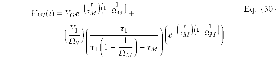
- V M1 ⁇ ( t ) ⁇ V G ⁇ ⁇ - ( t ⁇ M ) ⁇ ⁇ ( 1 - 1 ⁇ M ) + ⁇ ( V 1 ⁇ S ) ⁇ ⁇ ( ⁇ 1 ⁇ 1 ⁇ ⁇ ( 1 - 1 ⁇ M ) - ⁇ M ) ⁇ ⁇ ( ⁇ - ( t ⁇ M ) ⁇ ⁇ ( 1 - 1 ⁇ M ) ) Eq. (30)
- Equation 30 describes the residual voltage found on a cell at the end of ⁇ 1 .
- V M1 ⁇ ( t ) ( 1 ⁇ S ) ⁇ ⁇ ( ⁇ 1 ⁇ 1 ⁇ ⁇ ( 1 - 1 ⁇ M ) - ⁇ M ) ⁇ ⁇ ( ⁇ - t ⁇ M - ⁇ - ( t ⁇ M ) ⁇ ⁇ ( 1 - 1 ⁇ M ) ) Eq. (31)
- the optimal duration for ⁇ 1 may now be determined according to criteria for a desired cell response.
- One such criterion is that the duration of ⁇ 1 be equal to the time required for the external defibrillator shock pulse to bring the cell response to its maximum possible level.
- d ⁇ ⁇ 1 ( ⁇ 1 ⁇ ⁇ M ⁇ 1 ⁇ ( 1 - 1 ⁇ M ) - ⁇ M ) ⁇ ⁇ ln ⁇ ⁇ ( ⁇ 1 ⁇ ( 1 - 1 ⁇ M ) ⁇ M ) Eq. (33)
- the design equations for ⁇ 1 may be similarly determined. These design equations describe: (1) the myocardial cell membrane response to the transchest transfer function when plied with a second forcing function V S ; (2) the optimal pulse duration of ⁇ 2 ; and (3) the optimal capacitor for delivering ⁇ 2 .
- Equations 22 through 33 an analysis almost identical to Equations 22 through 33 above is derived. However, there are two identifiable differences. First, a biphasic waveform reverses the flow of current through the myocardium during ⁇ 2 . Reversing the flow of current in transthoracic cell response model 10 (FIG. 3 ,) changes the sign of the current and, as such, the sign on the right hand side of equation 22 is changed to a negative. Second, the C 2 capacitor bank, rather than the C 1 capacitor bank, delivers the shock pulse for ⁇ 2 and, as such, C 2 rather than C 1 is incorporated into the design equations. Correspondingly, the leading-edge voltage V 2 of C 2 is also incorporated into the design equations rather than leading-edge voltage V 1 .
- V M2 the initial value of V M2 is set equal to the voltage, V ⁇ 1 , left on the myocardial cell membrane at the end of the overall discharge time, d ⁇ 1 , of ⁇ 1 , i.e.,:
- Equation 35 V ⁇ ⁇ 1 - ⁇ ( V 2 ⁇ S ) ⁇ ⁇ ( ⁇ 2 ⁇ 2 ⁇ ( 1 - 1 ⁇ M ) - ⁇ M ) Eq . ⁇ ( 37 )
- V M2 ⁇ ( t ) ( V 2 ⁇ S ) ⁇ ( ⁇ 2 ⁇ 2 ⁇ ( 1 - 1 ⁇ M ) - ⁇ M ) ⁇ ( ⁇ - ( t ⁇ M ) ⁇ ( 1 - 1 ⁇ M ) - ⁇ - t ⁇ 2 ) + V ⁇ ⁇ 1 ⁇ ( ⁇ - ( t ⁇ M ) ⁇ ( 1 - 1 ⁇ M ) ) Eq . ⁇ ( 38 )
- Equation 38 provides the means to calculate the residual membrane potential at the end of ⁇ 2 for those myocardial membrane cells not stimulated by ⁇ 1 . Equation 38 is then preferably set equal to zero and solved for t to determine the optimal time duration for ⁇ 2 , designated d ⁇ 2 . By designing ⁇ 2 with the optimal duration, ⁇ 2 operates to remove the residual charge placed on the myocardial membrane cell by ⁇ 1 and helps to prevent refibrillation.
- an optimal monophasic defibrillation waveform or a biphasic defibrillation waveform may be calculated for an external defibrillator.
- the design of ⁇ 2 is substantially independent of ⁇ 1 .
- the only information necessary from ⁇ 1 is the residual voltage left on the myocardial cell membrane after delivery of the ⁇ 1 shock wave pulse.
- ⁇ 2 need not use the same or similar circuitry as ⁇ 1 to deliver its shock pulse waveform.
- ⁇ 1 may use the capacitive discharge circuit of FIG. 3, while ⁇ 2 may use the capacitor-inductor discharge circuit of FIG. 4B, and vice-versa.
- V 1 is the leading-edge voltage on the charging capacitor bank C 1
- ⁇ C1 RC 1
- ⁇ L1 L 1 R
- R R S + R B
- the equations developed above are preferably used to design the characteristics of a full-tilt exponential waveform that may be used for monophasic and biphasic external defibrillation.
- the design equations of the standard charge burping model may be used to design the characteristics of a full-tilt exponential waveform that may be used for monophasic and biphasic internal defibrillation.
- the waveform design characteristics are then preferably implemented within a pulse delivery circuit 100 as shown in FIG. 5 .
- Pulse delivery circuit 100 generally includes a pulse generator 112 connected to a pulse transformer 114 which, in turn, is connected to a passive rectifying and filtering circuit 116 .
- Passive rectifying and filtering circuit 116 incorporates a diode 118 and capacitor 120 , which is preferably in the 3-10 microFarad range.
- Circuit common is indicated by an inverted triangle 122 , and an output 123 of circuit 116 is connected to first and second charge switches 124 and 126 , respectively.
- Charge switches 124 and 126 are each preferably formed of one or more solid state switching devices such as a silicon controlled rectifier (SCR), a field effect transistor (FET), an insulated gate bipolar transistor (IGBT) or other appropriate device. Such devices may be connected in series (to increase voltage capability) or in parallel (to increase current capability) as is known in the art.
- SCR silicon controlled rectifier
- FET field effect transistor
- IGBT insulated gate bipolar transistor
- Each charge switch 124 and 126 is preferably controlled by a separate charge control circuit 128 and 130 , respectively. And, the respective outputs 132 and 134 of charge switches 124 and 126 are each individually connected to a capacitor bank; output 132 connected to capacitor bank 140 and output 134 connected to capacitor bank 142 . Note that additional capacitor banks may be included without departing from the spirit or scope of the invention.
- Capacitor bank 140 is monitored by monitor circuit 143 , which is connected between capacitor bank 140 and charge control circuit 128 .
- Capacitor bank 142 is monitored by monitor circuit 145 , which is connected between capacitor bank 142 and charge control circuit 130 .
- Voltage monitoring circuit 143 is illustrated in FIG. 6; voltage monitoring circuit 145 is the same as voltage monitoring circuit 143 .
- Voltage monitoring circuit 143 generally includes an operational amplifier 160 , an analog to digital converter 162 and a microprocessor 164 .
- Amplifier 160 is connected to capacitor bank 140 via a plurality of resistors 166 .
- voltage monitoring circuit 143 has a database of preset values stored in microprocessor 164 . When capacitor bank 140 reaches a preset charging voltage value, as selected in microprocessor 164 , charge control circuit 128 is instructed to halt the charging of capacitor bank 140 .
- other types of voltage monitoring circuits may be used within pulse delivery circuit 100 without departing from the spirit or scope of the invention.
- Pulse delivery circuit 100 further includes an output portion 168 that is connected to capacitor banks 140 , 142 .
- Output portion includes a selector circuit 170 and an isolator circuit 172 as indicated.
- Each capacitor bank 140 , 142 has respective phase delivery command lines 174 , 176 , which carry notice from selector switch 170 , 192 that either capacitor bank 140 or capacitor bank 142 is to release its energy.
- Selector circuit 170 has a pair of preferably identical selector subsystems 190 , 191 .
- Subsystem 190 includes a solid state phase selector switch 192 connected to a phase selector driver 194 which in turn is connected to a select phase control 196 , e.g., a microprocessor.
- subsystem 191 includes a solid state phase selector switch 193 connected to a phase selector driver 195 which in turn is connected to a select phase control 197 .
- Select phase controls 196 , 197 provide signals to activate and deactivate their respective phase selector drivers 194 , 195 .
- Selector circuit 170 is preferably under microprocessor control, e.g., microprocessor 164 , or, alternatively, may configured with other operable means such as hard wiring.
- pulse delivery circuit 100 In explaining the operation of pulse delivery circuit 100 it is presumed, by way of example, that capacitor bank 140 is configured to discharge a positive first phase of a biphasic output pulse and that capacitor bank 142 is configured to discharge a negative second phase.
- pulse delivery circuit 100 is designed to output to electrode terminals 147 and 149 a high voltage defibrillation pulse, e.g., 2000-3000 volts.
- a high voltage defibrillation pulse e.g. 2000-3000 volts.
- typical impedance values range between 25 and 225 ohms and, as such, currents in excess of 100 amps may be present.
- a two-step process is required.
- the first step is that of charging the capacitors.
- Charge control circuits 128 , 130 and charge switch circuits 124 , 126 are used to charge capacitor banks 140 , 142 to the desired voltage levels.
- the second step is that of delivering the defibrillation pulse.
- pulse generator 112 supplies a series, or train, of wave pulses.
- a square wave pulse at 50% duty cycle having an amplitude of approximately 400 volts, at a frequency between approximately 5 KHz and 500 KHz, is an appropriate wave pulse.
- the wave pulses have very fast rapid rise times. Since the fast rise times and high frequencies of the pulses cause typically cause avalanching of most common solid state devices of reasonable cost, the pulses are first passed through passive filter circuit 116 .
- Diode 118 is a fast recovery diode that provides for charging of capacitor 120 and prevents discharge of capacitor 120 through secondary 136 of pulse transformer 114 .
- step two that is the delivery of the full-tilt exponential defibrillation pulse waveform, preferably proceeds under the following sequence:
- Phase selector switch 193 is turned ON, providing a first, positive polarity, exponentially decaying portion of the defibrillation pulse to the patient.
- phase selector driver 195 is activated to drive selector switch 193 to a state of conduction (ON) between lines 176 and 178 , connecting capacitor bank 140 to isolator circuit 172 and ultimately to electrodes 147 , 149 to deliver the first phase of the full-tilt exponential waveform defibrillation pulse.
- Phase selector switch 193 is turned OFF, when current flowing through phase selector switch 193 is nearly zero; the current is determined to be nearly zero when monitor circuit 143 , by monitoring the voltage of capacitor bank 140 , determines that the voltage on capacitor bank 140 is close to zero.
- select phase control 197 deactivates its phase selector driver 195 whereby phase selector switch 193 is rendered nonconductive (OFF), thus, stopping any remainder (of which there is little) of the first phase portion of the biphasic pulse from being delivered from capacitor bank 140 .
- phase selector switch 192 is turned ON, providing a second, negative polarity, exponentially decaying portion of the pulse.
- phase selector driver 194 is activated to drive selector switch 192 to a state of conduction (ON) between lines 174 and 175 , connecting capacitor bank 142 to isolator circuit 172 and ultimately, to electrodes 147 , 149 to deliver the second phase of the full-tilt exponential waveform defibrillation pulse.
- Phase selector switch 192 is turned OFF, when current flowing through phase selector switch 192 is nearly zero; the current is determined to be nearly zero when monitor circuit 145 , by monitoring the voltage of capacitor bank 142 , determines that the voltage on capacitor bank 142 is close to zero.
- select phase control 196 deactivates its phase selector driver 194 whereby phase selector switch 192 is rendered nonconductive (OFF), thus, stopping any remainder (of which there is little) of the second phase portion of the biphasic pulse from being delivered from capacitor bank 142 .
- pulse delivery circuit 100 is essentially acting as a current controller in delivering a defibrillation.
- isolator circuit 172 is provided to keep the patient separate from the defibrillator and its defibrillation circuit 100 . Without isolator circuit 172 , leakage current from defibrillator circuit 100 might undesirably reach the patient and additional energy from the patient, such as that delivered by a second defibrillator, might reach defibrillation circuit 100 and alter its operation. More details regarding isolation circuits may be found in U.S. Pat. No. 5,909,138, which is hereby incorporated by reference.
- a biphasic full-tilt exponential waveform created by the steps above is shown in FIG. 7.
- a monophasic full-tilt exponential waveform comprises only the positive portion of FIG. 7 .
- phase selector switches 192 and 193 are not actuated when they are conducting significant amounts of current. Turning phase selector switches 192 and 193 OFF when the current flowing through it is small (relative to the current used for defibrillation) results in less stress on phase selector switches 192 and 193 and, thereby, less likelihood of switch failure.
- phase selector switch 193 would be turned OFF at time A and phase selector switch 192 would be turned OFF at time B thereby truncating the exponentially decaying pulse.
- This truncation occurs during the delivery of the pulse when there is still high current and high voltage flowing through the phase selector switch mechanisms causing great wear on the mechanism.
- great care must be taken to the design of switching mechanisms to assure that they may be switched off while a high voltage current is flowing through them.
- This great care is not required of the full-tilt exponential waveform and, as such, cheaper components may be used.
- the switches may be eliminated since truncation is essentially not required of the waveform.
- Pulse delivery circuit 100 is preferably implemented in an internal defibrillator, of which there are many available types, or in an external defibrillator.
- AED 210 includes a plastic case 212 with a carrying handle 214 .
- a lid 216 is provided which covers an electrode compartment 218 .
- An electrode connector 220 , a speaker 222 , and a diagnostic panel (not shown) are located on case 212 within electrode compartment 218 .
- a pair of electrodes 147 , 149 may be stored within compartment 218 and may be pre-connected to connector 220 .
- the operation of AED 210 is described briefly below.
- a rescue mode of AED 210 is initiated when lid 216 is opened to access electrodes 224 . The opening of lid 216 is detected by AED 210 to effectively turn on the device.
- AED 210 then quickly runs a short test routine. After electrodes 147 , 149 have been placed on the patient, AED 210 senses patient specific parameters such as impedance, voltage, current, charge, or other measurable parameters of the patient. Any or all of these patient specific parameters may be utilized to design optimal, full-tilt exponential pulse delivery waveforms as described in the sections above.
- pulse delivery circuit 100 located within AED 210 , operates to charge capacitor banks 140 , 142 from an energy source, typically a detachable battery pack. Based upon the patient specific parameters sensed, the duration and other characteristics of the full-tilt exponential discharge waveform (monophasic or biphasic) are then calculated per the design equations described above. A microprocessor preferably performs the calculations. Then, using pulse delivery circuit 100 and the energy stored in capacitor banks 140 , 142 , the full-tilt exponential waveform is discharged to the patient through electrodes 147 , 149 .
Abstract
Description


Claims (12)
Priority Applications (1)
| Application Number | Priority Date | Filing Date | Title |
|---|---|---|---|
| US09/354,300 US6539255B1 (en) | 1998-07-16 | 1999-07-16 | Full-tilt exponential defibrillation waveform |
Applications Claiming Priority (2)
| Application Number | Priority Date | Filing Date | Title |
|---|---|---|---|
| US9307798P | 1998-07-16 | 1998-07-16 | |
| US09/354,300 US6539255B1 (en) | 1998-07-16 | 1999-07-16 | Full-tilt exponential defibrillation waveform |
Publications (1)
| Publication Number | Publication Date |
|---|---|
| US6539255B1 true US6539255B1 (en) | 2003-03-25 |
Family
ID=22236863
Family Applications (1)
| Application Number | Title | Priority Date | Filing Date |
|---|---|---|---|
| US09/354,300 Expired - Fee Related US6539255B1 (en) | 1998-07-16 | 1999-07-16 | Full-tilt exponential defibrillation waveform |
Country Status (3)
| Country | Link |
|---|---|
| US (1) | US6539255B1 (en) |
| AU (1) | AU5316199A (en) |
| WO (1) | WO2000003761A1 (en) |
Cited By (17)
| Publication number | Priority date | Publication date | Assignee | Title |
|---|---|---|---|---|
| US6834050B1 (en) * | 2000-03-10 | 2004-12-21 | Telefonaktiebolaget Lm Ericsson (Publ) | Packet core function and method of selecting a packet data service node/foreign agent in a packet data network |
| WO2010146492A1 (en) | 2009-06-19 | 2010-12-23 | Koninklijke Philips Electronics, N.V. | Biphasic defibrillator waveform with adjustable second phase tilt |
| US20130282079A1 (en) * | 2012-04-24 | 2013-10-24 | Medtronic, Inc. | Charge-balancing during electrical stimulation |
| US10799709B2 (en) | 2017-06-20 | 2020-10-13 | Cellaed Life Saver Pty Ltd | Portable single use automated external defibrillator device |
| US10946207B2 (en) | 2017-05-27 | 2021-03-16 | West Affum Holdings Corp. | Defibrillation waveforms for a wearable cardiac defibrillator |
| US10953234B2 (en) | 2015-08-26 | 2021-03-23 | Element Science, Inc. | Wearable devices |
| US11103718B2 (en) | 2016-12-19 | 2021-08-31 | Hearthero, Inc. | Automated external defibrillator device and methods of use |
| US11185709B2 (en) | 2014-02-24 | 2021-11-30 | Element Science, Inc. | External defibrillator |
| USD942013S1 (en) | 2019-10-23 | 2022-01-25 | Cellaed Life Saver Pty Ltd | Defibrillator case |
| US11253715B2 (en) | 2018-10-10 | 2022-02-22 | Element Science, Inc. | Wearable medical device with disposable and reusable components |
| USD959668S1 (en) | 2020-08-31 | 2022-08-02 | Cellaed Life Saver Pty Ltd | Defibrillator |
| US11524168B2 (en) | 2016-12-19 | 2022-12-13 | Hearthero, Inc. | Self-contained, connected automated external defibrillator systems and methods of use |
| USD972730S1 (en) | 2020-08-31 | 2022-12-13 | Cellaed Life Saver Pty Ltd | Defibrillator |
| US11529526B1 (en) | 2021-12-10 | 2022-12-20 | Hearthero, Inc. | Automated external defibrillator |
| USD974563S1 (en) | 2019-11-04 | 2023-01-03 | Cellaed Life Saver Pty Ltd | Defibrillator |
| US11883676B2 (en) | 2020-10-14 | 2024-01-30 | Hearthero, Inc. | Automated external defibrillator systems with operation adjustment features according to temperature and methods of use |
| US11904177B2 (en) | 2021-01-28 | 2024-02-20 | Usa Medical Electronix, Inc. | Pocket-sized automated external defibrillator |
Citations (42)
| Publication number | Priority date | Publication date | Assignee | Title |
|---|---|---|---|---|
| US3241555A (en) * | 1962-06-25 | 1966-03-22 | Mine Safety Appliances Co | Charging and discharging circuit for ventricular defibrillator |
| US3590322A (en) | 1970-02-12 | 1971-06-29 | Sci Systems Inc | Medical instrumentation system |
| US3857398A (en) | 1971-12-13 | 1974-12-31 | L Rubin | Electrical cardiac defibrillator |
| US3862636A (en) | 1972-01-20 | 1975-01-28 | Health Technology Labs Inc | Computer controlled defibrillator |
| US3886950A (en) | 1973-10-01 | 1975-06-03 | Spacelabs Inc | Defibrillator |
| US4504773A (en) | 1981-09-10 | 1985-03-12 | Kureha Kagaku Kogyo Kabushiki Kaisha | Capacitor discharge circuit |
| US4610254A (en) | 1984-03-08 | 1986-09-09 | Physio-Control Corporation | Interactive portable defibrillator |
| US4619265A (en) | 1984-03-08 | 1986-10-28 | Physio-Control Corporation | Interactive portable defibrillator including ECG detection circuit |
| US4637397A (en) | 1985-05-30 | 1987-01-20 | Case Western Reserve University | Triphasic wave defibrillation |
| US4768512A (en) | 1986-05-13 | 1988-09-06 | Mieczyslaw Mirowski | Cardioverting system and method with high-frequency pulse delivery |
| US4800883A (en) | 1986-04-02 | 1989-01-31 | Intermedics, Inc. | Apparatus for generating multiphasic defibrillation pulse waveform |
| US4821723A (en) | 1987-02-27 | 1989-04-18 | Intermedics Inc. | Biphasic waveforms for defibrillation |
| US4823796A (en) | 1987-04-03 | 1989-04-25 | Laerdal Manufacturing Corp. | Defibrillator circuit for producing a trapezoidal defibrillation pulse |
| US4996984A (en) | 1989-09-26 | 1991-03-05 | Eli Lilly And Company | Defibrillation method |
| US4998531A (en) | 1990-03-28 | 1991-03-12 | Cardiac Pacemakers, Inc. | Implantable N-phasic defibrillator output bridge circuit |
| US5083562A (en) | 1988-01-19 | 1992-01-28 | Telectronics Pacing Systems, Inc. | Method and apparatus for applying asymmetric biphasic truncated exponential countershocks |
| US5097830A (en) | 1990-03-30 | 1992-03-24 | Laerdal Manufacturing Corporation | Defibrillator with reliability verification |
| WO1993001861A1 (en) | 1991-07-15 | 1993-02-04 | Zmd Corporation | Method and apparatus for transcutaneous cardiac pacing |
| US5193537A (en) | 1990-06-12 | 1993-03-16 | Zmd Corporation | Method and apparatus for transcutaneous electrical cardiac pacing |
| US5205284A (en) | 1990-06-12 | 1993-04-27 | Zoll Medical Corporation | Method and apparatus for transcutaneous electrical cardiac pacing with background stimulation |
| US5215081A (en) | 1989-12-28 | 1993-06-01 | Telectronics Pacing Systems, Inc. | Method and device for measuring subthreshold defibrillation electrode resistance and providing a constant energy shock delivery |
| US5275157A (en) | 1991-04-12 | 1994-01-04 | Physio-Control Corporation | Pulse forming circuits |
| US5350403A (en) * | 1992-06-17 | 1994-09-27 | Siemens Aktiengesellschaft | Apparatus for charging living tissue with electrical pulses |
| US5352239A (en) | 1990-12-18 | 1994-10-04 | Ventritex, Inc. | Apparatus for producing configurable biphastic defibrillation waveforms |
| US5372606A (en) | 1993-10-07 | 1994-12-13 | Cardiac Pacemakers, Inc. | Method and apparatus for generating adaptive n-phasic defibrillation waveforms |
| US5385575A (en) | 1992-03-24 | 1995-01-31 | Angeion Corporation | Implantable cardioverter defibrillator having variable output capacitance |
| GB2280377A (en) | 1993-07-19 | 1995-02-01 | Zmd Corp | Method and apparatus for transcutaneous electrical cardiac pacing |
| US5391186A (en) | 1993-12-13 | 1995-02-21 | Angeion Corporation | Method and apparatus for utilizing short tau capacitors in an implantable cardioverter defibrillator |
| WO1995005215A2 (en) | 1993-08-06 | 1995-02-23 | Heartstream, Inc. | Electrotherapy method and apparatus |
| US5405361A (en) | 1993-03-15 | 1995-04-11 | Surviva Link Corporation | External defibrillator circuit |
| WO1995009673A1 (en) | 1993-10-06 | 1995-04-13 | Duke University | Method and apparatus for delivering a shock with an optimum duration in treating arrhythmias |
| US5411525A (en) | 1992-01-30 | 1995-05-02 | Cardiac Pacemakers, Inc. | Dual capacitor biphasic defibrillator waveform generator employing selective connection of capacitors for each phase |
| US5411526A (en) | 1992-03-24 | 1995-05-02 | Angeion Corporation | Improved implantable defibrillator system for producing true-voltage-pulse waveforms |
| US5431686A (en) | 1992-02-18 | 1995-07-11 | Angeion Corporation | Method for optimal pulse defibrillation using an implantable defibrillator |
| US5468254A (en) | 1993-07-26 | 1995-11-21 | Cardiac Pacemakers, Inc. | Method and apparatus for defibrillation using a multiphasic truncated exponential waveform |
| WO1995032020A1 (en) | 1994-05-19 | 1995-11-30 | Angeion Corporation | Biphasic defibrillation waveform production method and apparatus |
| US5507778A (en) | 1994-02-22 | 1996-04-16 | Zmd Corporation | Semiautomatic defibrillator with synchronized shock delivery |
| US5540721A (en) * | 1991-12-17 | 1996-07-30 | Angeion Corporation | Process and apparatus for defibrillation system with a small capacitor |
| US5591209A (en) | 1994-05-19 | 1997-01-07 | Angeion Corporation | Implantable defibrillator system for generating an active biphasic waveform |
| US5593427A (en) | 1993-08-06 | 1997-01-14 | Heartstream, Inc. | Electrotherapy method |
| US5833712A (en) * | 1991-05-23 | 1998-11-10 | Angeion Corporation | Implantable defibrillator system for generating a biphasic waveform |
| US5991658A (en) * | 1996-07-01 | 1999-11-23 | Survivalink Corporation | Continual waveform shape reforming method and apparatus for transchest resistance dynamics |
-
1999
- 1999-07-16 US US09/354,300 patent/US6539255B1/en not_active Expired - Fee Related
- 1999-07-16 WO PCT/US1999/016093 patent/WO2000003761A1/en active Application Filing
- 1999-07-16 AU AU53161/99A patent/AU5316199A/en not_active Abandoned
Patent Citations (51)
| Publication number | Priority date | Publication date | Assignee | Title |
|---|---|---|---|---|
| US3241555A (en) * | 1962-06-25 | 1966-03-22 | Mine Safety Appliances Co | Charging and discharging circuit for ventricular defibrillator |
| US3590322A (en) | 1970-02-12 | 1971-06-29 | Sci Systems Inc | Medical instrumentation system |
| US3857398A (en) | 1971-12-13 | 1974-12-31 | L Rubin | Electrical cardiac defibrillator |
| US3862636A (en) | 1972-01-20 | 1975-01-28 | Health Technology Labs Inc | Computer controlled defibrillator |
| US3886950A (en) | 1973-10-01 | 1975-06-03 | Spacelabs Inc | Defibrillator |
| US4504773A (en) | 1981-09-10 | 1985-03-12 | Kureha Kagaku Kogyo Kabushiki Kaisha | Capacitor discharge circuit |
| US4610254A (en) | 1984-03-08 | 1986-09-09 | Physio-Control Corporation | Interactive portable defibrillator |
| US4619265A (en) | 1984-03-08 | 1986-10-28 | Physio-Control Corporation | Interactive portable defibrillator including ECG detection circuit |
| US4637397A (en) | 1985-05-30 | 1987-01-20 | Case Western Reserve University | Triphasic wave defibrillation |
| US4800883A (en) | 1986-04-02 | 1989-01-31 | Intermedics, Inc. | Apparatus for generating multiphasic defibrillation pulse waveform |
| US4768512A (en) | 1986-05-13 | 1988-09-06 | Mieczyslaw Mirowski | Cardioverting system and method with high-frequency pulse delivery |
| US4821723A (en) | 1987-02-27 | 1989-04-18 | Intermedics Inc. | Biphasic waveforms for defibrillation |
| US4823796A (en) | 1987-04-03 | 1989-04-25 | Laerdal Manufacturing Corp. | Defibrillator circuit for producing a trapezoidal defibrillation pulse |
| US5083562A (en) | 1988-01-19 | 1992-01-28 | Telectronics Pacing Systems, Inc. | Method and apparatus for applying asymmetric biphasic truncated exponential countershocks |
| US4996984A (en) | 1989-09-26 | 1991-03-05 | Eli Lilly And Company | Defibrillation method |
| US5215081A (en) | 1989-12-28 | 1993-06-01 | Telectronics Pacing Systems, Inc. | Method and device for measuring subthreshold defibrillation electrode resistance and providing a constant energy shock delivery |
| US4998531A (en) | 1990-03-28 | 1991-03-12 | Cardiac Pacemakers, Inc. | Implantable N-phasic defibrillator output bridge circuit |
| US5097830A (en) | 1990-03-30 | 1992-03-24 | Laerdal Manufacturing Corporation | Defibrillator with reliability verification |
| US5205284A (en) | 1990-06-12 | 1993-04-27 | Zoll Medical Corporation | Method and apparatus for transcutaneous electrical cardiac pacing with background stimulation |
| US5431688A (en) | 1990-06-12 | 1995-07-11 | Zmd Corporation | Method and apparatus for transcutaneous electrical cardiac pacing |
| US5193537A (en) | 1990-06-12 | 1993-03-16 | Zmd Corporation | Method and apparatus for transcutaneous electrical cardiac pacing |
| US5282843A (en) | 1990-06-12 | 1994-02-01 | Zmd Corporation | Electrodes and method for transcutaneous cardiac pacing |
| US5352239A (en) | 1990-12-18 | 1994-10-04 | Ventritex, Inc. | Apparatus for producing configurable biphastic defibrillation waveforms |
| US5275157A (en) | 1991-04-12 | 1994-01-04 | Physio-Control Corporation | Pulse forming circuits |
| US5833712A (en) * | 1991-05-23 | 1998-11-10 | Angeion Corporation | Implantable defibrillator system for generating a biphasic waveform |
| WO1993001861A1 (en) | 1991-07-15 | 1993-02-04 | Zmd Corporation | Method and apparatus for transcutaneous cardiac pacing |
| US5540721A (en) * | 1991-12-17 | 1996-07-30 | Angeion Corporation | Process and apparatus for defibrillation system with a small capacitor |
| US5411525A (en) | 1992-01-30 | 1995-05-02 | Cardiac Pacemakers, Inc. | Dual capacitor biphasic defibrillator waveform generator employing selective connection of capacitors for each phase |
| US5534015A (en) | 1992-02-18 | 1996-07-09 | Angeion Corporation | Method and apparatus for generating biphasic waveforms in an implantable defibrillator |
| US5431686A (en) | 1992-02-18 | 1995-07-11 | Angeion Corporation | Method for optimal pulse defibrillation using an implantable defibrillator |
| US5385575A (en) | 1992-03-24 | 1995-01-31 | Angeion Corporation | Implantable cardioverter defibrillator having variable output capacitance |
| US5411526A (en) | 1992-03-24 | 1995-05-02 | Angeion Corporation | Improved implantable defibrillator system for producing true-voltage-pulse waveforms |
| US5350403A (en) * | 1992-06-17 | 1994-09-27 | Siemens Aktiengesellschaft | Apparatus for charging living tissue with electrical pulses |
| US5405361A (en) | 1993-03-15 | 1995-04-11 | Surviva Link Corporation | External defibrillator circuit |
| GB2280377A (en) | 1993-07-19 | 1995-02-01 | Zmd Corp | Method and apparatus for transcutaneous electrical cardiac pacing |
| US5468254A (en) | 1993-07-26 | 1995-11-21 | Cardiac Pacemakers, Inc. | Method and apparatus for defibrillation using a multiphasic truncated exponential waveform |
| US5607454A (en) | 1993-08-06 | 1997-03-04 | Heartstream, Inc. | Electrotherapy method and apparatus |
| US5735879A (en) | 1993-08-06 | 1998-04-07 | Heartstream, Inc. | Electrotherapy method for external defibrillators |
| US5749904A (en) | 1993-08-06 | 1998-05-12 | Heartstream, Inc. | Electrotherapy method utilizing patient dependent electrical parameters |
| US5749905A (en) | 1993-08-06 | 1998-05-12 | Heartstream, Inc. | Electrotherapy method utilizing patient dependent electrical parameters |
| US5601612A (en) | 1993-08-06 | 1997-02-11 | Heartstream, Inc. | Method for applying a multiphasic waveform |
| WO1995005215A2 (en) | 1993-08-06 | 1995-02-23 | Heartstream, Inc. | Electrotherapy method and apparatus |
| US5593427A (en) | 1993-08-06 | 1997-01-14 | Heartstream, Inc. | Electrotherapy method |
| US5540723A (en) | 1993-10-06 | 1996-07-30 | Duke University | Method and apparatus for delivering an optimum shock duration in treating cardiac arrhythmias |
| WO1995009673A1 (en) | 1993-10-06 | 1995-04-13 | Duke University | Method and apparatus for delivering a shock with an optimum duration in treating arrhythmias |
| US5372606A (en) | 1993-10-07 | 1994-12-13 | Cardiac Pacemakers, Inc. | Method and apparatus for generating adaptive n-phasic defibrillation waveforms |
| US5391186A (en) | 1993-12-13 | 1995-02-21 | Angeion Corporation | Method and apparatus for utilizing short tau capacitors in an implantable cardioverter defibrillator |
| US5507778A (en) | 1994-02-22 | 1996-04-16 | Zmd Corporation | Semiautomatic defibrillator with synchronized shock delivery |
| US5591209A (en) | 1994-05-19 | 1997-01-07 | Angeion Corporation | Implantable defibrillator system for generating an active biphasic waveform |
| WO1995032020A1 (en) | 1994-05-19 | 1995-11-30 | Angeion Corporation | Biphasic defibrillation waveform production method and apparatus |
| US5991658A (en) * | 1996-07-01 | 1999-11-23 | Survivalink Corporation | Continual waveform shape reforming method and apparatus for transchest resistance dynamics |
Non-Patent Citations (20)
| Title |
|---|
| "A Conceptual Basis for Defibrillation Waveforms," Brian G. Cleland, Pacing and Clinical Electrophysiology, Future Publishing Co., vol. 19, No. 8, pp. 1186-1195, Aug. 1996. |
| "A Mathematical Model of Make and Break Electrical Stimulation of Cardiac Tissue by a Unipolar Anode or Cathode," Bradley J. Roth, Biomedical Engineering, vol. 42, No. 12, pp. 1174-1184, Dec. 1995. |
| "A Minimal Model of the Single Capacitor Biphasic Defibrillation Waveform," Mark W. Kroll, Pacing and Clinical Electrophysiology, Future Publishing Co., vol. 17, No. 11, Part I, pp. 1782-1792, Nov. 1994. |
| "Choosing the Optimal Monophasic and Biphasic Waveforms for Ventricular Defibrillation," G.P. Walcott, R. G. Walker, A. W. Cates, W. Krassowska, W. M. Smith, R. E. Ideker, Journal of Cardiovascular Electrophysiology, Futura Publishing Co., vol. 6, No. 9, pp. 737-750, Sep. 1995. |
| "Defibrillation of the Heart", W.A. Tacker, Jr., Chapter 10, pp. 196-222, 1994. |
| "Improved Defibrillation Thresholds With Large Contoured Epicardial Electrodes and Biphasic Waveforms," E.G. Dixon, A.S.L. Tang, P.D. Wolf, J.T. Meador, M.J. Fine, R.V. Calfee, R.E. Ideker, Circulation, American Heart Association, vol. 76, No. 5, pp. 1176-1184, Nov. 1987. |
| "Low Voltage Shocks Have a Significantly Higher Tilt of the Internal Electric Field Than Do High Voltage Shocks," by James E. Brewer et al., Pacing and Clinical Electrophysiology, vol. 18, No. 1, Part II, pp. 214-220, Jan. 1995. |
| "Mechanisms for Electrical Stimulation of Excitable Tissue," by B.J. Roth, Critical Reviews In Biomedical Engineering, vol. 22, Issues 3 & 4, pp. 253-305, 1994. |
| "Multicenter Comparison of Truncated Biphasic Shocks and Standard Damped Sine Wave Monophasic Shocks for Transthoracic Ventricular Defibrillation," G.H. Bardy, F.E. Marchlinski, A.D. Sharma, S.J. Worley, R.M. Luceri, R. Yee, B.D. Halperin, C.L. Fellows, T.S. Ahern, D.A. Chilson, D.L. Packer, D.J. Wilber, T.A. Mattioni, R. Reddy, R.A. Kronmal, R. Lazzara, Circulation, American Heart Associate, vol. 94, No. 10, pp. 2507-2514, Nov. 1996. |
| "On The Intensity-Time Relations For Stimulation By Electric Currents. I," H.A. Blair, The Journal of General Physiology, Rockefeller Institute for Medical Research, vol. 15, pp. 709-729, 1932. |
| "On The Intensity-Time Relations for Stimulation By Electric Currents. II", H.A. Blair, The Journal of General Physiology, Rockefeller Institute for Medical Research, vol. 15, pp. 731-755, 1932. |
| "Optimal Truncation of Defibrillation Pulses," Werner Irnich, Pacing and Clinical Electrophysiology, Futura Publishing Co., vol. 18, No. 4, pp. 673-688, Apr. 1995. |
| "Optimizing Defibrillation Through Improved Waveforms," Michael Block and Günter Breithardt, Pacing and Clinical Electrophysiology, Futura Publishing Co., vol. 18, No. 3, Part II, pp. 526-538, Mar. 1995. |
| "The Effect of Externally Applied Electrical Fields on Myocardial Tissue," Bradley J. Roth and John P. Wikswo, Jr., Proceedings of the IEEE, vol. 84, No. 3, pp. 379-391, Mar. 1996. |
| "Transthoracic Defibrillation of Swing With Monophasic and Biphase Waveforms," B.E. Gliner, T.E. Lyster, S.M. Dillion, G.H. Bardy, Circulation, American Heart Association, vol. 92, No. 6, pp. 1634-1643, Sep. 1995. |
| "Truncated Biphasic Pulses for Transthoracic Defibrillation," G.H. Bardy, B.E. Gliner, P.J. Kudenchuk, J.E. Poole, G.L. Dolack, G. K. Jones, J. Anderson, C. Troutman, G. Johnson, Circulation, American Heart Association, vol. 91, No. 6, pp. 1768-1774, Mar. 1995. |
| "Ventricular Defibrillation Using Biphasic Waveforms: The Importance of Phasic Duration," A.S.L. Tang, S. Yabe, J. M. Wharton, M. Doker, W.M. Smith, R. E. Ideker, Journal of the American College of Cardiology, American College of Cardiology, vol. 13, No. 1, pp. 207-214, Jan. 1989. |
| "Virtual Electrodes in Cardiac Tissue: A Common Mechanism for Anodal and Cathodal Stimulation," John P. Wikswo, Jr., Shien-Fong Lin, Rashida A. Abbas, Biophysics Journal, vol. 69, No. 6, pp. 2195-2210, Dec. 1995. |
| A Minimal Model of the Monophasic Defibrillation Pulse, Mark W. Kroll, Pacing and Clinical Electrophysiology, Futura Publishing Co., vol. 16, No. 4, Part I, pp. 769-777, Apr. 1993. |
| Strength-Duration and Probability of Success Curves for Defibrillation With Biphasic Waveforms, S.A. Feeser, A.S.L. Tang, K.M. Kavanagh, D.L. Rollins, W.M. Smith, P.D. Wolf, R.E. Ideker, Circulation, American Heart Association, vol. 82, No. 6, pp. 2128-2141, Dec. 1990. |
Cited By (21)
| Publication number | Priority date | Publication date | Assignee | Title |
|---|---|---|---|---|
| US6834050B1 (en) * | 2000-03-10 | 2004-12-21 | Telefonaktiebolaget Lm Ericsson (Publ) | Packet core function and method of selecting a packet data service node/foreign agent in a packet data network |
| WO2010146492A1 (en) | 2009-06-19 | 2010-12-23 | Koninklijke Philips Electronics, N.V. | Biphasic defibrillator waveform with adjustable second phase tilt |
| US10028721B2 (en) | 2009-06-19 | 2018-07-24 | Koninklijke Philips N.V. | Biphasic defibrillator waveform with adjustable second phase tilt |
| US20130282079A1 (en) * | 2012-04-24 | 2013-10-24 | Medtronic, Inc. | Charge-balancing during electrical stimulation |
| US9295850B2 (en) * | 2012-04-24 | 2016-03-29 | Medtronic, Inc. | Charge-balancing during electrical stimulation |
| US11185709B2 (en) | 2014-02-24 | 2021-11-30 | Element Science, Inc. | External defibrillator |
| US10953234B2 (en) | 2015-08-26 | 2021-03-23 | Element Science, Inc. | Wearable devices |
| US11701521B2 (en) | 2015-08-26 | 2023-07-18 | Element Science, Inc. | Wearable devices |
| US11103718B2 (en) | 2016-12-19 | 2021-08-31 | Hearthero, Inc. | Automated external defibrillator device and methods of use |
| US11524168B2 (en) | 2016-12-19 | 2022-12-13 | Hearthero, Inc. | Self-contained, connected automated external defibrillator systems and methods of use |
| US10946207B2 (en) | 2017-05-27 | 2021-03-16 | West Affum Holdings Corp. | Defibrillation waveforms for a wearable cardiac defibrillator |
| US11648411B2 (en) | 2017-05-27 | 2023-05-16 | West Affum Holdings Dac | Defibrillation waveforms for a wearable cardiac defibrillator |
| US10799709B2 (en) | 2017-06-20 | 2020-10-13 | Cellaed Life Saver Pty Ltd | Portable single use automated external defibrillator device |
| US11253715B2 (en) | 2018-10-10 | 2022-02-22 | Element Science, Inc. | Wearable medical device with disposable and reusable components |
| USD942013S1 (en) | 2019-10-23 | 2022-01-25 | Cellaed Life Saver Pty Ltd | Defibrillator case |
| USD974563S1 (en) | 2019-11-04 | 2023-01-03 | Cellaed Life Saver Pty Ltd | Defibrillator |
| USD972730S1 (en) | 2020-08-31 | 2022-12-13 | Cellaed Life Saver Pty Ltd | Defibrillator |
| USD959668S1 (en) | 2020-08-31 | 2022-08-02 | Cellaed Life Saver Pty Ltd | Defibrillator |
| US11883676B2 (en) | 2020-10-14 | 2024-01-30 | Hearthero, Inc. | Automated external defibrillator systems with operation adjustment features according to temperature and methods of use |
| US11904177B2 (en) | 2021-01-28 | 2024-02-20 | Usa Medical Electronix, Inc. | Pocket-sized automated external defibrillator |
| US11529526B1 (en) | 2021-12-10 | 2022-12-20 | Hearthero, Inc. | Automated external defibrillator |
Also Published As
| Publication number | Publication date |
|---|---|
| WO2000003761A1 (en) | 2000-01-27 |
| AU5316199A (en) | 2000-02-07 |
Similar Documents
| Publication | Publication Date | Title |
|---|---|---|
| US5891173A (en) | Method of designing external defibrillator waveforms | |
| US6539255B1 (en) | Full-tilt exponential defibrillation waveform | |
| US5413591A (en) | Current truncated waveform defibrillator | |
| EP0722349B1 (en) | Apparatus for delivering a shock with an optimum duration in treating arrhythmias | |
| CA2088384C (en) | Defibrillator waveform generator for generating waveform of long duration | |
| US6567698B2 (en) | System and method for applying sequential low energy defibrillation pulses | |
| US6484056B2 (en) | System and method of generating a high efficiency biphasic defibrillation waveform for use in an implantable cardioverter/defibrillator (ICD) | |
| US8352033B2 (en) | Apparatus and methods for measuring defibrillation lead impedance via a high magnitude, short duration current pulse | |
| US7962207B2 (en) | Method and apparatus for variable capacitance defibrillation | |
| US5718718A (en) | Method and apparatus for polarity reversal of consecutive defibrillation countershocks having back biasing precharge pulses | |
| US7463923B2 (en) | Method and apparatus for delivering a biphasic defibrillation pulse with variable energy | |
| US5741303A (en) | Electrode back-charging pre-treatment system for an implantable cardioverter defibrillator | |
| US5902323A (en) | Method and apparatus for external defibrillation using a device having a low capacitance and small time constant | |
| US5968080A (en) | Method for determining the second phase of external defibrillator devices | |
| EP0547878B1 (en) | Defibrillation system with a small capacitor | |
| US6263239B1 (en) | Method and apparatus for determining the second phase of defibrillator devices | |
| WO1998044990A1 (en) | Aami specification optimized truncated exponential waveform |
Legal Events
| Date | Code | Title | Description |
|---|---|---|---|
| AS | Assignment |
Owner name: SURVIVALINK CORPORATION, MINNESOTA Free format text: ASSIGNMENT OF ASSIGNORS INTEREST;ASSIGNOR:BREWER, JAMES E.;REEL/FRAME:010392/0137 Effective date: 19991021 |
|
| AS | Assignment |
Owner name: HSBC BANK, USA, NEW YORK Free format text: SECURITY AGREEMENT;ASSIGNOR:CARDIAC SCIENCE, INC.;REEL/FRAME:013146/0001 Effective date: 20020530 |
|
| AS | Assignment |
Owner name: CARDIAC SCIENCE, INC., MINNESOTA Free format text: ASSIGNMENT OF ASSIGNORS INTEREST;ASSIGNOR:SURVIVALINK CORPORATION;REEL/FRAME:013280/0068 Effective date: 20020718 |
|
| FEPP | Fee payment procedure |
Free format text: PAT HOLDER NO LONGER CLAIMS SMALL ENTITY STATUS, ENTITY STATUS SET TO UNDISCOUNTED (ORIGINAL EVENT CODE: STOL); ENTITY STATUS OF PATENT OWNER: LARGE ENTITY |
|
| REFU | Refund |
Free format text: REFUND - SURCHARGE, PETITION TO ACCEPT PYMT AFTER EXP, UNINTENTIONAL (ORIGINAL EVENT CODE: R2551); ENTITY STATUS OF PATENT OWNER: LARGE ENTITY |
|
| FPAY | Fee payment |
Year of fee payment: 4 |
|
| AS | Assignment |
Owner name: CARDIAC SCIENCE CORPORATION, WASHINGTON Free format text: MERGER;ASSIGNOR:CARDIAC SCIENCE, INC.;REEL/FRAME:018296/0274 Effective date: 20060224 |
|
| AS | Assignment |
Owner name: SILICON VALLEY BANK,CALIFORNIA Free format text: SECURITY AGREEMENT;ASSIGNOR:CARDIAC SCIENCE, INC.;REEL/FRAME:024492/0931 Effective date: 20100607 Owner name: SILICON VALLEY BANK, CALIFORNIA Free format text: SECURITY AGREEMENT;ASSIGNOR:CARDIAC SCIENCE, INC.;REEL/FRAME:024492/0931 Effective date: 20100607 |
|
| FPAY | Fee payment |
Year of fee payment: 8 |
|
| AS | Assignment |
Owner name: CARDIAC SCIENCE CORPORATION, WASHINGTON Free format text: RELEASE BY SECURED PARTY;ASSIGNOR:SILICON VALLEY BANK;REEL/FRAME:029389/0937 Effective date: 20121012 |
|
| AS | Assignment |
Owner name: DBS BANK LTD., BANGALORE BRANCH, INDIA Free format text: SECURITY AGREEMENT;ASSIGNOR:CARDIAC SCIENCE CORPORATION;REEL/FRAME:029733/0469 Effective date: 20121228 |
|
| REMI | Maintenance fee reminder mailed | ||
| LAPS | Lapse for failure to pay maintenance fees | ||
| STCH | Information on status: patent discontinuation |
Free format text: PATENT EXPIRED DUE TO NONPAYMENT OF MAINTENANCE FEES UNDER 37 CFR 1.362 |
|
| FP | Lapsed due to failure to pay maintenance fee |
Effective date: 20150325 |
|
| AS | Assignment |
Owner name: ZOLL MEDICAL CORPORATION, MASSACHUSETTS Free format text: ASSIGNMENT OF ASSIGNORS INTEREST;ASSIGNOR:CARDIAC SCIENCE CORPORATION;REEL/FRAME:056391/0439 Effective date: 20210409 |