US6526150B2 - Telephone loudspeaker enclosure - Google Patents
Telephone loudspeaker enclosure Download PDFInfo
- Publication number
- US6526150B2 US6526150B2 US09/113,538 US11353898A US6526150B2 US 6526150 B2 US6526150 B2 US 6526150B2 US 11353898 A US11353898 A US 11353898A US 6526150 B2 US6526150 B2 US 6526150B2
- Authority
- US
- United States
- Prior art keywords
- speaker
- housing member
- recited
- enclosure
- speaker enclosure
- Prior art date
- Legal status (The legal status is an assumption and is not a legal conclusion. Google has not performed a legal analysis and makes no representation as to the accuracy of the status listed.)
- Expired - Lifetime
Links
Images


Classifications
-
- H—ELECTRICITY
- H04—ELECTRIC COMMUNICATION TECHNIQUE
- H04M—TELEPHONIC COMMUNICATION
- H04M1/00—Substation equipment, e.g. for use by subscribers
- H04M1/02—Constructional features of telephone sets
- H04M1/20—Arrangements for preventing acoustic feed-back
-
- H—ELECTRICITY
- H04—ELECTRIC COMMUNICATION TECHNIQUE
- H04M—TELEPHONIC COMMUNICATION
- H04M1/00—Substation equipment, e.g. for use by subscribers
- H04M1/02—Constructional features of telephone sets
- H04M1/03—Constructional features of telephone transmitters or receivers, e.g. telephone hand-sets
-
- H—ELECTRICITY
- H04—ELECTRIC COMMUNICATION TECHNIQUE
- H04R—LOUDSPEAKERS, MICROPHONES, GRAMOPHONE PICK-UPS OR LIKE ACOUSTIC ELECTROMECHANICAL TRANSDUCERS; ELECTRIC HEARING AIDS; PUBLIC ADDRESS SYSTEMS
- H04R1/00—Details of transducers, loudspeakers or microphones
- H04R1/02—Casings; Cabinets ; Supports therefor; Mountings therein
- H04R1/025—Arrangements for fixing loudspeaker transducers, e.g. in a box, furniture
Definitions
- the present invention relates to an apparatus which includes a speaker and a microphone, such as a telephone, intercom, two-way radio and the like, and more particularly, to an apparatus which includes a speaker and a microphone which provides acoustical and mechanical isolation between the speaker and a microphone to provide improved audio performance as well as allow for streamlined manufacturing of the apparatus and thus reduced costs.
- Various apparatus which include speakers and microphones, carried by a common housing. Speaker phones, intercoms, two-way radios and the like are examples of such apparatus.
- First, such apparatus are known to have undesirable audio performance resulting from non-linear mechanical coupling between the speaker and the microphone. More particularly, in many known apparatus, the speaker energy is known to cause non-linear vibration of the microphone support structure which carries the microphone which, in turn, is coupled to the microphone.
- the loudspeaker energy is known to cause vibration of various parts within the apparatus, which can produce non-linear vibrational noise, known to be acoustically coupled to the microphone.
- Third, the second waves from behind the speaker are known to cancel sound waves in front of the speaker, thus degrading audio performance.
- an apparatus is formed with a sealed chamber behind the speaker which provides improved isolation between the speaker and microphone to prevent sound waves behind the speaker from cancelling sound waves in front of the speaker.
- the speaker is mechanically isolated from the apparatus housing in order to improve performance of the system.
- a pliant material such as a damping material with a relatively linear compression characteristic, such as a thermal plastic elastomer, may be used to isolate the speaker from the apparatus housings as well as providing a relatively air tight chamber behind the speaker.
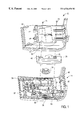
- FIG. 1 is an exploded perspective view of a telephone in accordance with the present invention illustrating the structure and alignment of the speaker enclosure in accordance with the present invention, shown with the printed circuit cards and the microphone removed for clarity.
- FIG. 2 is a simplified elevational view of the telephone illustrated in FIG. 1, shown assembled, illustrating the contact points between the speaker enclosure and the base and top cover.
- FIG. 3 is a mechanical schematic illustrated the isolation of the speaker enclosure and the base and top cover of the telephone illustrated in FIG. 1 .
- FIG. 4 is a top plan view of the speaker enclosure in accordance with the present invention shown with a main gasket and a pair of shoulder gaskets and retaining washers removed.
- FIG. 5 is similar to FIG. 4 but illustrates a bottom view of the speaker enclosure illustrated in FIG. 4 .
- FIG. 6 is an exploded perspective view of a speaker and speaker gasket for use with the present invention.
- the present invention relates to an apparatus which houses a speaker and a microphone.
- the apparatus is described in terms of a telephone and in particular a speaker phone.
- the principals of the present invention are readily applicable to other types of apparatus which include a speaker and a microphone carried by a common housing, such as an intercom, two-way radio and the like.
- FIG. 1 a telephone in accordance with the present invention is illustrated and generally identified with the reference numeral 20 .
- the telephone 20 is shown disassembled and upside down for purposes of clarity.
- the telephone includes a first housing member or base unit 22 , a second housing member or a top cover 24 , a speaker enclosure 26 and a speaker 28 .
- Other components of the telephone such as printed circuit cards, a microphone are removed for clarity.
- the configuration of the telephone 20 provides several distinct advantages over known telephone speaker phones.
- the configuration provides mechanical and acoustical isolation between the speaker 28 and a microphone (not shown), in order to improve the overall audio performance of the system.
- the configuration of the telephone 20 allows for greatly reduced assembly time as well as a reduction of the number of parts which makes it suitable for top down manufacturing, thus reducing the overall cost of the telephone 20 .
- the sealed chamber 30 is formed behind the speaker 28 .
- the sealed chamber 30 improves the audio performance of the telephone 20 .
- the sealed chamber 30 is formed when the top cover 24 , speaker enclosure 26 and base 22 are assembled together.
- the configuration illustrated in FIG. 2 not only provides an airtight chamber 30 behind the speaker 28 but also mechanically isolates the speaker 28 from the speaker enclosure 26 as well as the base 22 .
- the sealed chamber 30 behind the speaker 28 performs two functions. First, it improves the low frequency response of the speaker 28 be prevented sound waves behind the speaker 28 from cancelling those in front of the speaker 28 , which improves the natural sounding voice quality. Secondly, the sealed chamber 30 minimizes sound pressure inside the telephone 20 , which provides improved isolation between the speaker 28 and the microphone. In particular, the sealed chamber 30 reduces the vibration of a microphone support structure 34 (FIG. 1 ), formed in the top cover 24 for carrying the microphone. A reduction of the vibration of the microphone support structure 34 reduces non-linear mechanical coupling of the speaker 28 energy into the microphone.
- the sealed chamber 30 reduces vibration of the keypad (not shown) as well as other parts of the telephone 20 , known to produce undesired non-linear vibration noise, known to be acoustically coupled to the microphone.
- the configuration in accordance with the present invention provides acoustical and mechanical isolation of the microphone from the speaker 38 which improves the operational stability of the apparatus and provides improved response of the system by minimizing non-linear mechanical coupling and vibrational noise which cannot be canceled by an echo canceler.
- the top cover 24 may be an injection molded piece as shown, formed with a plurality of ribs 32 for rigidity.
- the top cover 22 may be formed with the microphone support structure 34 as well as a speaker support structure 36 for the speaker 28 .
- the support structures 34 and 38 can be formed on different housing members, or both formed in the base. As shown, the microphone support structure 34 and the speaker support structure 36 are spaced apart to minimize acoustical coupling.
- a support structure 38 is formed in the top cover 24 for carrying a printed circuit board (not shown). The printed circuit board has been removed for clarity. The printed circuit board is adapted to be secured to a threaded post 40 .
- the base 22 may also be formed from plastic and be injection molded.
- the top cover 24 is configured to seat against the base 22 . However, as will be discussed in more detailed below, all of the contact points between the base 22 , top cover 24 , the speaker enclosure 26 and speaker 28 are by way of a pliant material, such as a damping material having a linear compression characteristic. As such, the speaker 28 as well as the speaker enclosure 26 is mechanically isolated from the base 22 and the top cover 24 .
- the telephone 20 is formed with a reduced number of parts and configured to facilitate alignment of the parts, which reduces the assembly time of telephone 20 therefore reducing the cost.
- the top cover 24 may be formed with a speaker support structure 36 .
- the speaker support structure 36 is formed with an annular wall 36 to facilitate alignment of the speaker 28 relative to the top cover 24 .
- the speaker 28 is not placed in direct contact with the speaker mounting structure 36 . Rather a gasket 42 or other damping material is placed between the top cover 24 and the speaker 28 .
- the gasket 42 not only mechanically isolates the speaker 28 from the top cover 24 , but also forms a part of the seal to form the air tight chamber 30 behind the speaker 28 , as shown best in FIG. 2 .
- FIGS. 4 and 5 Another aspect of the invention relates to the speaker enclosure 26 , shown in FIGS. 4 and 5.
- a main gasket or damping material 43 (FIG. 2) which may be attached to the speaker enclosure 26 , is used for several reasons as follows: to provide mechanical isolation between the top cover 24 and the speaker enclosure 26 ; to form the sealed chamber 30 behind the speaker; and to hold the speaker 28 in place against the top cover 24 .
- the speaker enclosure 26 may be formed as in injection molded part, for example, from clear plastic, to facilitate alignment.
- the speaker enclosure 26 may be formed with an irregular shape as shown with a plurality of ribs 41 on the under side for rigidity.
- the speaker enclosure 26 is formed with a cavity 44 for receiving the back of the speaker 28 and also for forming the chamber 30 behind the speaker 28 .
- Disposed adjacent the cavity 44 are a pair of countersunk apertures, identified with the reference numerals 46 and 48 .
- the countersunk apertures 46 and 48 are adapted to receive shoulder gaskets 50 and 52 .
- the shoulder gaskets 50 and 52 are formed with central apertures 54 and 54 which enable the shoulder gaskets 50 and 52 to fit over a pair of screw posts 58 and 59 formed in the top cover 24 .
- the shoulder gaskets 50 and 52 seal the speaker enclosure 26 around the screw posts 58 and 59 as well as mechanically isolate the speaker enclosure 26 from the top cover 24 and the base 22 .
- the apertures 46 and 48 formed in the speaker enclosure 26 as well as the apertures 54 and 56 formed in the shoulder gaskets 50 and 56 are adapted to be aligned with a pair of apertures 61 and 63 formed in the base 22 .
- a pair of flat washers 62 and 64 are adapted to be received in a recessed area on the top of the shoulder gaskets 50 and 52 .
- Each of the flat washers 62 and 64 may be formed with one or more radial extending tabs 63 and 64 may be formed with one or more radial extending tabs 63 and 65 that are adapted to be received in corresponding radially disposed apertures 67 and 69 , formed in the shoulder gaskets 50 and 52 and 64 in order to secure the flat washers 62 and 64 relative to the shoulder gaskets 50 and 52 .
- the speaker enclosure 26 is assembled to the top cover 22 by aligning the apertures 46 and 48 with the screw posts 58 and 59 .
- the shoulder gaskets 50 and 52 are positioned over the screw posts 58 and 59 and the top cover 24 and seated in the countersunk apertures 46 and 48 , formed in the speaker enclosure 26 .
- the flat washers 62 and 64 may either be mounted to the shoulder washers 50 and 52 at the time or may be assembled to the shoulder washers 50 and 52 beforehand.
- the base 22 is then aligned with the top cover 24 .
- the apertures 58 and 60 formed in the bottom of the base are aligned with the screw posts 58 and 59 formed in the top cover 24 .
- the base 22 is then secured to the top cover 24 by way of suitable fasteners 71 and 73 .
- the shoulder gaskets 50 and 52 perform several functions. First, they slide over the screw posts 58 and 59 to align the speaker enclosure 26 relative to the top cover 24 . Second, the shoulder gaskets 50 and 52 hold the speaker enclosure 26 in place as the partially assembled device moves down the assembly line to the screw station. In addition, the shoulder gasket 50 and 52 provide mechanical isolation between the speaker enclosure 26 , the top cover 24 and the base 22 , as best shown in FIG. 2 .
- a main gasket 43 is used as the contact points between the top cover 24 and the speaker enclosure 26 , shown best in FIGS. 4 and 5.
- the gasket 43 is formed with a generally U-shaped cross-section and formed generally to conform to the shape of the speaker enclosure 26 .
- the U-shaped cross-section facilitates alignment and assembly of the gasket 43 to the speaker enclosure 26 .
- the U-shaped cross-section is formed by an interior sidewall portion 68 and an exterior sidewall portion 70 defining a trench portion 72 therebetween.
- the trench portion 72 is adapted to receive a portion of an extending sidewall 74 , formed around the speaker enclosure 26 .
- the inner wall 68 of the speaker enclosure 26 may be formed with increased height portions 74 at the corners as well as at various other portions along the gasket 43 . These portions increase the contact area between the speaker enclosure 26 and the gasket 43 to help hold the gasket 43 in place.
- the gasket 43 is used to hold the speaker 28 in place.
- the gasket 43 is formed with a pair of inwardly projecting arms 78 and 80 . These arms 78 , 80 project inward relative to each other, as best shown in FIGS. 4 and 5.
- the arms 78 and 80 hold the back of the speaker 28 against the top cover 24 as best shown in FIG. 2 .
- the telephone 20 can be molded as illustrated in FIG. 3 .
- Each of the gaskets or other damping material is represented by a spring.
- the speaker 28 as well as the enclosure body 26 are mechanically isolated from the top cover 24 and the base 22 as well as from each other. As mentioned above, mechanical isolation of the speaker 28 reduces non-linear mechanical coupling to the microphone and also minimizes non-linear vibrational noise within the telephone 20 which can be acoustically coupled to the telephone, thereby improving the performance of the system.
- gaskets 42 , 50 , 52 and 43 are shown. These gaskets may be formed from a material with linear compression characteristic, such as injection molded thermal plastic elastomer (TPE). However, any pliant material such as a damping material with a linear compression characteristic is suitable. In embodiments of the invention in which a sealed chamber is formed behind the speaker, the pliant material must be able to be amenable to sealing to form the sealed chamber 30 .
- TPE injection molded thermal plastic elastomer
Landscapes
- Engineering & Computer Science (AREA)
- Signal Processing (AREA)
- Physics & Mathematics (AREA)
- Acoustics & Sound (AREA)
- Telephone Set Structure (AREA)
- Details Of Audible-Bandwidth Transducers (AREA)
Abstract
Description
Claims (17)
Priority Applications (3)
| Application Number | Priority Date | Filing Date | Title |
|---|---|---|---|
| US09/113,538 US6526150B2 (en) | 1998-07-10 | 1998-07-10 | Telephone loudspeaker enclosure |
| EP99111416A EP0978978A3 (en) | 1998-07-10 | 1999-06-11 | Telephone loudspeaker enclosure |
| JP11193154A JP2000101699A (en) | 1998-07-10 | 1999-07-07 | Telephone loud speaker enclosure |
Applications Claiming Priority (1)
| Application Number | Priority Date | Filing Date | Title |
|---|---|---|---|
| US09/113,538 US6526150B2 (en) | 1998-07-10 | 1998-07-10 | Telephone loudspeaker enclosure |
Publications (2)
| Publication Number | Publication Date |
|---|---|
| US20020057816A1 US20020057816A1 (en) | 2002-05-16 |
| US6526150B2 true US6526150B2 (en) | 2003-02-25 |
Family
ID=22350015
Family Applications (1)
| Application Number | Title | Priority Date | Filing Date |
|---|---|---|---|
| US09/113,538 Expired - Lifetime US6526150B2 (en) | 1998-07-10 | 1998-07-10 | Telephone loudspeaker enclosure |
Country Status (3)
| Country | Link |
|---|---|
| US (1) | US6526150B2 (en) |
| EP (1) | EP0978978A3 (en) |
| JP (1) | JP2000101699A (en) |
Cited By (30)
| Publication number | Priority date | Publication date | Assignee | Title |
|---|---|---|---|---|
| US20010031059A1 (en) * | 2000-04-18 | 2001-10-18 | Alberto Borgonovo | Cabinet for audio devices |
| US20020139608A1 (en) * | 2001-03-27 | 2002-10-03 | Star Micronics Co., Ltd. | Speaker holder |
| US20020170772A1 (en) * | 2001-05-16 | 2002-11-21 | Masato Asahina | One-piece speaker assembly |
| US20030087676A1 (en) * | 2001-11-02 | 2003-05-08 | Lloyd Grant Harries | Speakerphone Accessory |
| US20040170291A1 (en) * | 2003-02-28 | 2004-09-02 | Eaton W. Chris | Mobile device with improved acoustic porting |
| US20040202343A1 (en) * | 2003-04-11 | 2004-10-14 | Rye Ryan P. | Speakerphone accessory assembly |
| US20040253995A1 (en) * | 2003-06-13 | 2004-12-16 | Fujitsu Limited | Mobile terminal |
| US20040264728A1 (en) * | 2003-04-22 | 2004-12-30 | Cornelius Sperle | Electronic device with loudspeaker |
| US20060126879A1 (en) * | 2004-12-10 | 2006-06-15 | Hsien-Hung Kuo | Speaker module |
| US20060188123A1 (en) * | 2005-02-17 | 2006-08-24 | Hiromitsu Sasaki | Frame for speaker device and speaker device |
| US20060239488A1 (en) * | 2001-04-04 | 2006-10-26 | Sonion Nederland B.V. | Acoustic receiver having improved mechanical suspension |
| US20060237257A1 (en) * | 2005-02-17 | 2006-10-26 | Hiromitsu Sasaki | Frame for speaker device and speaker device |
| US20070068729A1 (en) * | 2005-09-29 | 2007-03-29 | Asustek Computer Inc. | Speaker with vibration-proof design |
| US20070123294A1 (en) * | 2005-11-01 | 2007-05-31 | Samsung Electronics Co., Ltd. | Speaker device for portable terminal using antenna mounting space |
| US20080144879A1 (en) * | 2006-12-15 | 2008-06-19 | Foxconn Technology Co., Ltd. | Speaker set and mobile phone incorporating the same |
| US20080219490A1 (en) * | 2007-03-07 | 2008-09-11 | Foxconn Technology Co., Ltd. | Speaker set for electronic product |
| US20080219489A1 (en) * | 2007-03-07 | 2008-09-11 | Foxconn Technology Co., Ltd. | Speaker set and electronic product incorporating the same |
| US7565178B1 (en) * | 2005-08-16 | 2009-07-21 | Kyocera Wireless Corp. | Portable handset with integrated speaker |
| US7628271B1 (en) * | 2005-08-11 | 2009-12-08 | Richard Marton | Multi-functional carrying case for laptops and like portable computers |
| US20100177921A1 (en) * | 2009-01-14 | 2010-07-15 | Richard Bos | Response speaker system |
| US20140133684A1 (en) * | 2012-11-15 | 2014-05-15 | Aac Acoustic Technologies (Shenzhen) Co., Ltd. | Acoustic Device |
| US9167324B2 (en) | 2012-07-30 | 2015-10-20 | Samsung Electronics Co., Ltd. | Speaker module for portable terminal |
| US20150358705A1 (en) * | 2013-01-18 | 2015-12-10 | Goertek Inc. | Ultrathin speaker module |
| US9843850B2 (en) | 2015-09-26 | 2017-12-12 | Intel Corporation | Audio speakers with integrated sealing and assembly features for “caseless” installation |
| US20180139523A1 (en) * | 2015-08-04 | 2018-05-17 | Yamaha Corporation | Sound output device |
| US20190149900A1 (en) * | 2017-11-13 | 2019-05-16 | Denso Ten Limited | Electronic control apparatus |
| US10932020B2 (en) * | 2018-08-01 | 2021-02-23 | AAC Technologies Pte. Ltd. | Sound generator |
| US20230007388A1 (en) * | 2021-06-30 | 2023-01-05 | Nintendo Co., Ltd. | Electronic device |
| US12401940B2 (en) | 2020-08-04 | 2025-08-26 | Samsung Electronics Co., Ltd. | Speaker module and electronic device including speaker module |
| US20260075355A1 (en) * | 2024-09-12 | 2026-03-12 | Micro-Star Int’L Co., Ltd. | Electronic device and damper |
Families Citing this family (18)
| Publication number | Priority date | Publication date | Assignee | Title |
|---|---|---|---|---|
| US6415036B1 (en) * | 2000-08-24 | 2002-07-02 | Thomson Licensing, S.A. | Apparatus for reducing vibrations generated by a loudspeaker in a television cabinet |
| DE10121523A1 (en) * | 2001-05-03 | 2002-11-07 | Siemens Ag | Electronic device with a loudspeaker device |
| DE102004001215B3 (en) * | 2004-01-06 | 2005-04-21 | Elac Electroacustic Gmbh | Removable frame for exciter of flat membrane loudspeaker has inner ring holding membrane and fitting in outer ring with set of spring clips |
| JP4435019B2 (en) * | 2005-02-15 | 2010-03-17 | パイオニア株式会社 | Loudspeaker speaker system |
| US8351632B2 (en) | 2005-08-23 | 2013-01-08 | Analog Devices, Inc. | Noise mitigating microphone system and method |
| US8130979B2 (en) | 2005-08-23 | 2012-03-06 | Analog Devices, Inc. | Noise mitigating microphone system and method |
| KR20080010625A (en) * | 2006-07-27 | 2008-01-31 | 삼성전자주식회사 | Mobile devices |
| DE102006034852B3 (en) * | 2006-07-27 | 2008-03-27 | Siemens Home And Office Communication Devices Gmbh & Co. Kg | Telephone terminal |
| US8005517B2 (en) * | 2006-10-25 | 2011-08-23 | Lg Electronics Inc. | Mobile communication device |
| CN201878204U (en) * | 2010-11-15 | 2011-06-22 | 中兴通讯股份有限公司 | Mobile phone device |
| CN102348002A (en) * | 2011-07-15 | 2012-02-08 | 深圳市迪美通讯设备有限公司 | Speaker sound cavity box with sound-guiding pipe groove |
| DE102015220565A1 (en) * | 2015-10-21 | 2017-04-27 | Peter Plonski | Horn-shaped sound enhancement device |
| CN105578362B (en) * | 2016-03-16 | 2019-01-04 | 珠海格力电器股份有限公司 | Horn assembly and electronic equipment |
| JP2019101169A (en) * | 2017-11-30 | 2019-06-24 | シャープ株式会社 | Image formation device |
| US11451903B2 (en) | 2020-01-20 | 2022-09-20 | Epos Group A/S | System for reducing vibrations in loudspeaker |
| CN113329279A (en) | 2020-02-28 | 2021-08-31 | 苏州佳世达电通有限公司 | Display and sound output device thereof |
| TWI743697B (en) * | 2020-03-06 | 2021-10-21 | 佳世達科技股份有限公司 | Display and sound emitting device |
| US20230224631A1 (en) * | 2022-01-10 | 2023-07-13 | Shure Acquisition Holdings, Inc. | Beamforming microphone with loudspeaker |
Citations (12)
| Publication number | Priority date | Publication date | Assignee | Title |
|---|---|---|---|---|
| US3257516A (en) * | 1962-06-25 | 1966-06-21 | Knowles Electronies Inc | Combined instrument and transducer motor cavities for acoustic instrument |
| US4453045A (en) * | 1981-09-24 | 1984-06-05 | Akg Akustische U. Kino-Gerate Gesellschaft M.B.H. | Supporting arrangement for electroacoustic transducers |
| US4550429A (en) * | 1983-06-03 | 1985-10-29 | Motorola, Inc. | Shock absorbing transducer module |
| US4845760A (en) * | 1985-10-25 | 1989-07-04 | Siemens Aktiengesellschaft | Electro-acoustic transducer arranged within the handset of a telephone instrument |
| US5883966A (en) * | 1994-11-08 | 1999-03-16 | Nec Corporation | Portable telephone with a speaker having an improved acoustic characteristic |
| US6002949A (en) * | 1997-11-18 | 1999-12-14 | Nortel Networks Corporation | Handset with a single transducer for handset and handsfree functionality |
| US6018584A (en) * | 1996-11-06 | 2000-01-25 | Motorola, Inc. | Electronic component assembly for an electronic device and method of assembling the same |
| US6021195A (en) * | 1997-12-11 | 2000-02-01 | Sony Corporation Of Japan | Telephone with configurable ear piece |
| US6026283A (en) * | 1997-12-05 | 2000-02-15 | Ericsson Inc. | Electrically conductive keypad lightguides |
| US6038328A (en) * | 1997-07-07 | 2000-03-14 | Hughes Electronics Corporation | Minimization of acoustic echo effects in a microphone boot |
| US6038327A (en) * | 1997-02-28 | 2000-03-14 | U.S. Philips Corporation | Electroacoustic transducer comprising a closing member for closing the rear volume of the transducer |
| US6058315A (en) * | 1996-03-13 | 2000-05-02 | Motorola, Inc. | Speaker assembly for a radiotelephone |
Family Cites Families (2)
| Publication number | Priority date | Publication date | Assignee | Title |
|---|---|---|---|---|
| US5081674A (en) * | 1990-05-14 | 1992-01-14 | Motorola, Inc. | Double annular ring speaker gasket |
| CA2169641C (en) * | 1993-08-18 | 2004-01-20 | Telefonaktiebolaget Lm Ericsson | Telephone handset |
-
1998
- 1998-07-10 US US09/113,538 patent/US6526150B2/en not_active Expired - Lifetime
-
1999
- 1999-06-11 EP EP99111416A patent/EP0978978A3/en not_active Withdrawn
- 1999-07-07 JP JP11193154A patent/JP2000101699A/en active Pending
Patent Citations (12)
| Publication number | Priority date | Publication date | Assignee | Title |
|---|---|---|---|---|
| US3257516A (en) * | 1962-06-25 | 1966-06-21 | Knowles Electronies Inc | Combined instrument and transducer motor cavities for acoustic instrument |
| US4453045A (en) * | 1981-09-24 | 1984-06-05 | Akg Akustische U. Kino-Gerate Gesellschaft M.B.H. | Supporting arrangement for electroacoustic transducers |
| US4550429A (en) * | 1983-06-03 | 1985-10-29 | Motorola, Inc. | Shock absorbing transducer module |
| US4845760A (en) * | 1985-10-25 | 1989-07-04 | Siemens Aktiengesellschaft | Electro-acoustic transducer arranged within the handset of a telephone instrument |
| US5883966A (en) * | 1994-11-08 | 1999-03-16 | Nec Corporation | Portable telephone with a speaker having an improved acoustic characteristic |
| US6058315A (en) * | 1996-03-13 | 2000-05-02 | Motorola, Inc. | Speaker assembly for a radiotelephone |
| US6018584A (en) * | 1996-11-06 | 2000-01-25 | Motorola, Inc. | Electronic component assembly for an electronic device and method of assembling the same |
| US6038327A (en) * | 1997-02-28 | 2000-03-14 | U.S. Philips Corporation | Electroacoustic transducer comprising a closing member for closing the rear volume of the transducer |
| US6038328A (en) * | 1997-07-07 | 2000-03-14 | Hughes Electronics Corporation | Minimization of acoustic echo effects in a microphone boot |
| US6002949A (en) * | 1997-11-18 | 1999-12-14 | Nortel Networks Corporation | Handset with a single transducer for handset and handsfree functionality |
| US6026283A (en) * | 1997-12-05 | 2000-02-15 | Ericsson Inc. | Electrically conductive keypad lightguides |
| US6021195A (en) * | 1997-12-11 | 2000-02-01 | Sony Corporation Of Japan | Telephone with configurable ear piece |
Cited By (54)
| Publication number | Priority date | Publication date | Assignee | Title |
|---|---|---|---|---|
| US20010031059A1 (en) * | 2000-04-18 | 2001-10-18 | Alberto Borgonovo | Cabinet for audio devices |
| US7496207B2 (en) * | 2000-04-18 | 2009-02-24 | Thomson Licensing | Cabinet for audio devices |
| US20020139608A1 (en) * | 2001-03-27 | 2002-10-03 | Star Micronics Co., Ltd. | Speaker holder |
| US6675930B2 (en) * | 2001-03-27 | 2004-01-13 | Star Micronics Co., Ltd. | Speaker holder |
| US7206428B2 (en) * | 2001-04-04 | 2007-04-17 | Sonion Nederland B.V. | Acoustic receiver having improved mechanical suspension |
| US20060239488A1 (en) * | 2001-04-04 | 2006-10-26 | Sonion Nederland B.V. | Acoustic receiver having improved mechanical suspension |
| US20020170772A1 (en) * | 2001-05-16 | 2002-11-21 | Masato Asahina | One-piece speaker assembly |
| US6876743B2 (en) * | 2001-05-16 | 2005-04-05 | Citizen Electronics Co., Ltd. | One-piece speaker assembly |
| US20030087676A1 (en) * | 2001-11-02 | 2003-05-08 | Lloyd Grant Harries | Speakerphone Accessory |
| US6836676B2 (en) * | 2001-11-02 | 2004-12-28 | Motorola, Inc. | Speakerphone accessory |
| US20040170291A1 (en) * | 2003-02-28 | 2004-09-02 | Eaton W. Chris | Mobile device with improved acoustic porting |
| US7505602B2 (en) * | 2003-02-28 | 2009-03-17 | Sony Ericsson Mobile Communications Ab | Mobile device with improved acoustic porting |
| US7088838B2 (en) | 2003-04-11 | 2006-08-08 | Motorola, Inc. | Speakerphone accessory assembly |
| US20040202343A1 (en) * | 2003-04-11 | 2004-10-14 | Rye Ryan P. | Speakerphone accessory assembly |
| US20040264728A1 (en) * | 2003-04-22 | 2004-12-30 | Cornelius Sperle | Electronic device with loudspeaker |
| US7302075B2 (en) * | 2003-04-22 | 2007-11-27 | Thomson Licensing | Electronic device with loudspeaker |
| US7400910B2 (en) * | 2003-06-13 | 2008-07-15 | Fujitsu Limited | Speaker sound enhancement for a mobile terminal |
| US20040253995A1 (en) * | 2003-06-13 | 2004-12-16 | Fujitsu Limited | Mobile terminal |
| US20060126879A1 (en) * | 2004-12-10 | 2006-06-15 | Hsien-Hung Kuo | Speaker module |
| US20060237257A1 (en) * | 2005-02-17 | 2006-10-26 | Hiromitsu Sasaki | Frame for speaker device and speaker device |
| US20060188123A1 (en) * | 2005-02-17 | 2006-08-24 | Hiromitsu Sasaki | Frame for speaker device and speaker device |
| US7325648B2 (en) * | 2005-02-17 | 2008-02-05 | Pioneer Corporation | Frame for speaker device and speaker device |
| US7377358B2 (en) * | 2005-02-17 | 2008-05-27 | Pioneer Corporation | Frame for speaker device and speaker device |
| US7628271B1 (en) * | 2005-08-11 | 2009-12-08 | Richard Marton | Multi-functional carrying case for laptops and like portable computers |
| US7565178B1 (en) * | 2005-08-16 | 2009-07-21 | Kyocera Wireless Corp. | Portable handset with integrated speaker |
| US20070068729A1 (en) * | 2005-09-29 | 2007-03-29 | Asustek Computer Inc. | Speaker with vibration-proof design |
| US20070123294A1 (en) * | 2005-11-01 | 2007-05-31 | Samsung Electronics Co., Ltd. | Speaker device for portable terminal using antenna mounting space |
| US7556121B2 (en) * | 2006-12-15 | 2009-07-07 | Foxconn Technology Co., Ltd. | Speaker set and mobile phone incorporating the same |
| US20080144879A1 (en) * | 2006-12-15 | 2008-06-19 | Foxconn Technology Co., Ltd. | Speaker set and mobile phone incorporating the same |
| US20080219489A1 (en) * | 2007-03-07 | 2008-09-11 | Foxconn Technology Co., Ltd. | Speaker set and electronic product incorporating the same |
| US20080219490A1 (en) * | 2007-03-07 | 2008-09-11 | Foxconn Technology Co., Ltd. | Speaker set for electronic product |
| US7578367B2 (en) * | 2007-03-07 | 2009-08-25 | Foxconn Technology Co., Ltd. | Speaker set and electronic product incorporating the same |
| US7578368B2 (en) * | 2007-03-07 | 2009-08-25 | Foxconn Technology Co., Ltd. | Speaker set for electronic product |
| US20100177921A1 (en) * | 2009-01-14 | 2010-07-15 | Richard Bos | Response speaker system |
| US9167324B2 (en) | 2012-07-30 | 2015-10-20 | Samsung Electronics Co., Ltd. | Speaker module for portable terminal |
| US9154865B2 (en) * | 2012-11-15 | 2015-10-06 | Aac Microtech (Changzhou) Co., Ltd. | Acoustic device |
| US20140133684A1 (en) * | 2012-11-15 | 2014-05-15 | Aac Acoustic Technologies (Shenzhen) Co., Ltd. | Acoustic Device |
| US20150358705A1 (en) * | 2013-01-18 | 2015-12-10 | Goertek Inc. | Ultrathin speaker module |
| US9525933B2 (en) * | 2013-01-18 | 2016-12-20 | Goertek Inc. | Ultrathin speaker module |
| US10820076B2 (en) * | 2015-08-04 | 2020-10-27 | Yamaha Corporation | Sound output device |
| US11375304B2 (en) | 2015-08-04 | 2022-06-28 | Yamaha Corporation | Sound output device |
| US10958998B2 (en) * | 2015-08-04 | 2021-03-23 | Yamaha Corporation | Sound output device |
| US20180139523A1 (en) * | 2015-08-04 | 2018-05-17 | Yamaha Corporation | Sound output device |
| US9843850B2 (en) | 2015-09-26 | 2017-12-12 | Intel Corporation | Audio speakers with integrated sealing and assembly features for “caseless” installation |
| US9888306B2 (en) * | 2015-09-26 | 2018-02-06 | Intel Corporation | Audio speakers with integrated sealing and assembly features for “caseless” installation |
| US11006195B2 (en) | 2015-09-26 | 2021-05-11 | Intel Corporation | Audio speakers with integrated sealing and assembly features for “caseless” installation |
| US20170359640A1 (en) * | 2015-09-26 | 2017-12-14 | Intel Corporation | Audio speakers with integrated sealing and assembly features for "caseless" installation |
| US10491976B2 (en) * | 2017-11-13 | 2019-11-26 | Denso Ten Limited | Electronic control apparatus |
| US20190149900A1 (en) * | 2017-11-13 | 2019-05-16 | Denso Ten Limited | Electronic control apparatus |
| US10932020B2 (en) * | 2018-08-01 | 2021-02-23 | AAC Technologies Pte. Ltd. | Sound generator |
| US12401940B2 (en) | 2020-08-04 | 2025-08-26 | Samsung Electronics Co., Ltd. | Speaker module and electronic device including speaker module |
| US20230007388A1 (en) * | 2021-06-30 | 2023-01-05 | Nintendo Co., Ltd. | Electronic device |
| US11743632B2 (en) * | 2021-06-30 | 2023-08-29 | Nintendo Co., Ltd. | Electronic device |
| US20260075355A1 (en) * | 2024-09-12 | 2026-03-12 | Micro-Star Int’L Co., Ltd. | Electronic device and damper |
Also Published As
| Publication number | Publication date |
|---|---|
| EP0978978A3 (en) | 2003-04-02 |
| US20020057816A1 (en) | 2002-05-16 |
| EP0978978A2 (en) | 2000-02-09 |
| JP2000101699A (en) | 2000-04-07 |
Similar Documents
| Publication | Publication Date | Title |
|---|---|---|
| US6526150B2 (en) | Telephone loudspeaker enclosure | |
| US5343523A (en) | Telephone headset structure for reducing ambient noise | |
| US8081790B2 (en) | Loudspeaker structure of electronic device | |
| US6975740B2 (en) | Waterproof acoustic structure applicable in conjunction with speaker | |
| CN1230027C (en) | Voice generator | |
| US4984268A (en) | Telephone handset construction | |
| AU687439B2 (en) | Telephone handset | |
| US7400910B2 (en) | Speaker sound enhancement for a mobile terminal | |
| US7088838B2 (en) | Speakerphone accessory assembly | |
| WO1992022176A1 (en) | Noise cancelling microphone and boot mounting arrangement | |
| US5216711A (en) | Telephone handset including directional microphone module | |
| US5210793A (en) | Apparatus for mounting transducers | |
| CA2094616C (en) | Compact loudspeaker assembly | |
| KR100540678B1 (en) | Portable Communication Terminals and Electroacoustic Converters Used in the Same | |
| US4550429A (en) | Shock absorbing transducer module | |
| GB2393352A (en) | Speaker system with two enclosures having complementary frequency responses | |
| US5058154A (en) | Telephone handset having a pure acoustic resistance connection | |
| CN1242645C (en) | Voice generator | |
| US4506759A (en) | Loudspeaker enclosure arrangement for voice communication terminals | |
| US20020028693A1 (en) | Electronic device | |
| JPS62110349A (en) | Transmitter | |
| JPH0946403A (en) | Water-proof structure for sounder | |
| CN219068347U (en) | Acoustic device and mobile terminal | |
| EP0944220B1 (en) | Audio diaphragm mounting arrangements in radio telephone handsets | |
| EP0129320B1 (en) | Loudspeaker enclosure arrangement for voice communication terminals |
Legal Events
| Date | Code | Title | Description |
|---|---|---|---|
| AS | Assignment |
Owner name: SIEMENS BUSINESS COMMUNCATIONS SYSTEMS, INC., CALI Free format text: ASSIGNMENT OF ASSIGNORS INTEREST;ASSIGNORS:KELLY, DANIEL B.;KIHNEMAN, JASON B.;MCKINNON, WAYNE E.;REEL/FRAME:009504/0224 Effective date: 19980914 |
|
| AS | Assignment |
Owner name: SIEMENS INFORMATION AND COMMUNICATION NETWORKS, IN Free format text: CERTIFICATE OF MERGER;ASSIGNOR:SIEMENS BUSINESS COMMUNICATION SYSTEMS, INC.;REEL/FRAME:013636/0853 Effective date: 19980930 Owner name: SIEMENS INFORMATION AND COMMUNICATION MOBILE, LLC. Free format text: CHANGE OF NAME;ASSIGNOR:SIEMENS INFORMATION AND COMMUNICATION PRODUCTS, LLC;REEL/FRAME:013636/0454 Effective date: 20000417 Owner name: SIEMENS INFORMATION AND COMMUNICATION PRODUCTS, LL Free format text: ASSIGNMENT AND ASSUMPTION;ASSIGNOR:SIEMENS INFORMATION AND COMMUNICATION NETWORKS, INC.;REEL/FRAME:013636/0859 Effective date: 19981001 |
|
| STCF | Information on status: patent grant |
Free format text: PATENTED CASE |
|
| REMI | Maintenance fee reminder mailed | ||
| FPAY | Fee payment |
Year of fee payment: 4 |
|
| SULP | Surcharge for late payment | ||
| FPAY | Fee payment |
Year of fee payment: 8 |
|
| AS | Assignment |
Owner name: SIEMENS COMMUNICATIONS, INC., FLORIDA Free format text: MERGER;ASSIGNORS:SIEMENS INFORMATION AND COMMUNICATION MOBILE LLC;SIEMENS INFORMATION AND COMMUNICATION NETWORKS, INC.;REEL/FRAME:028341/0612 Effective date: 20040922 Owner name: SIEMENS ENTERPRISE COMMUNICATIONS, INC., FLORIDA Free format text: ASSIGNMENT OF ASSIGNORS INTEREST;ASSIGNOR:SIEMENS COMMUNICATIONS, INC.;REEL/FRAME:028341/0858 Effective date: 20100304 |
|
| FPAY | Fee payment |
Year of fee payment: 12 |
|
| AS | Assignment |
Owner name: UNIFY GMBH & CO. KG, GERMANY Free format text: ASSIGNMENT OF ASSIGNORS INTEREST;ASSIGNOR:UNIFY INC.;REEL/FRAME:036434/0247 Effective date: 20150409 |
|
| AS | Assignment |
Owner name: UNIFY, INC., FLORIDA Free format text: TERMINATION AND RELEASE OF SECURITY INTEREST IN PATENTS;ASSIGNOR:WELLS FARGO TRUST CORPORATION LIMITED;REEL/FRAME:036574/0383 Effective date: 20140929 |
|
| AS | Assignment |
Owner name: ENTERPRISE SYSTEMS TECHNOLOGIES S.A.R.L., LUXEMBOURG Free format text: ASSIGNMENT OF ASSIGNORS INTEREST;ASSIGNOR:ENTERPRISE TECHNOLOGIES S.A.R.L. & CO. KG;REEL/FRAME:036987/0803 Effective date: 20141118 Owner name: ENTERPRISE SYSTEMS TECHNOLOGIES S.A.R.L., LUXEMBOU Free format text: ASSIGNMENT OF ASSIGNORS INTEREST;ASSIGNOR:ENTERPRISE TECHNOLOGIES S.A.R.L. & CO. KG;REEL/FRAME:036987/0803 Effective date: 20141118 Owner name: ENTERPRISE TECHNOLOGIES S.A.R.L. & CO. KG, GERMANY Free format text: DEMERGER;ASSIGNOR:UNIFY GMBH & CO. KG;REEL/FRAME:037008/0751 Effective date: 20140327 |