US6523893B2 - Vehicle seat frame - Google Patents
Vehicle seat frame Download PDFInfo
- Publication number
- US6523893B2 US6523893B2 US09/846,594 US84659401A US6523893B2 US 6523893 B2 US6523893 B2 US 6523893B2 US 84659401 A US84659401 A US 84659401A US 6523893 B2 US6523893 B2 US 6523893B2
- Authority
- US
- United States
- Prior art keywords
- crosspiece
- vehicle seat
- overlapping
- recited
- notches
- Prior art date
- Legal status (The legal status is an assumption and is not a legal conclusion. Google has not performed a legal analysis and makes no representation as to the accuracy of the status listed.)
- Expired - Fee Related
Links
Images


Classifications
-
- B—PERFORMING OPERATIONS; TRANSPORTING
- B60—VEHICLES IN GENERAL
- B60N—SEATS SPECIALLY ADAPTED FOR VEHICLES; VEHICLE PASSENGER ACCOMMODATION NOT OTHERWISE PROVIDED FOR
- B60N2/00—Seats specially adapted for vehicles; Arrangement or mounting of seats in vehicles
- B60N2/24—Seats specially adapted for vehicles; Arrangement or mounting of seats in vehicles for particular purposes or particular vehicles
- B60N2/42—Seats specially adapted for vehicles; Arrangement or mounting of seats in vehicles for particular purposes or particular vehicles the seat constructed to protect the occupant from the effect of abnormal g-forces, e.g. crash or safety seats
- B60N2/4207—Seats specially adapted for vehicles; Arrangement or mounting of seats in vehicles for particular purposes or particular vehicles the seat constructed to protect the occupant from the effect of abnormal g-forces, e.g. crash or safety seats characterised by the direction of the g-forces
- B60N2/4235—Seats specially adapted for vehicles; Arrangement or mounting of seats in vehicles for particular purposes or particular vehicles the seat constructed to protect the occupant from the effect of abnormal g-forces, e.g. crash or safety seats characterised by the direction of the g-forces transversal
-
- B—PERFORMING OPERATIONS; TRANSPORTING
- B60—VEHICLES IN GENERAL
- B60N—SEATS SPECIALLY ADAPTED FOR VEHICLES; VEHICLE PASSENGER ACCOMMODATION NOT OTHERWISE PROVIDED FOR
- B60N2/00—Seats specially adapted for vehicles; Arrangement or mounting of seats in vehicles
- B60N2/24—Seats specially adapted for vehicles; Arrangement or mounting of seats in vehicles for particular purposes or particular vehicles
- B60N2/42—Seats specially adapted for vehicles; Arrangement or mounting of seats in vehicles for particular purposes or particular vehicles the seat constructed to protect the occupant from the effect of abnormal g-forces, e.g. crash or safety seats
- B60N2/4207—Seats specially adapted for vehicles; Arrangement or mounting of seats in vehicles for particular purposes or particular vehicles the seat constructed to protect the occupant from the effect of abnormal g-forces, e.g. crash or safety seats characterised by the direction of the g-forces
- B60N2/4214—Seats specially adapted for vehicles; Arrangement or mounting of seats in vehicles for particular purposes or particular vehicles the seat constructed to protect the occupant from the effect of abnormal g-forces, e.g. crash or safety seats characterised by the direction of the g-forces longitudinal
- B60N2/4228—Seats specially adapted for vehicles; Arrangement or mounting of seats in vehicles for particular purposes or particular vehicles the seat constructed to protect the occupant from the effect of abnormal g-forces, e.g. crash or safety seats characterised by the direction of the g-forces longitudinal due to impact coming from the rear
-
- B—PERFORMING OPERATIONS; TRANSPORTING
- B60—VEHICLES IN GENERAL
- B60N—SEATS SPECIALLY ADAPTED FOR VEHICLES; VEHICLE PASSENGER ACCOMMODATION NOT OTHERWISE PROVIDED FOR
- B60N2/00—Seats specially adapted for vehicles; Arrangement or mounting of seats in vehicles
- B60N2/24—Seats specially adapted for vehicles; Arrangement or mounting of seats in vehicles for particular purposes or particular vehicles
- B60N2/42—Seats specially adapted for vehicles; Arrangement or mounting of seats in vehicles for particular purposes or particular vehicles the seat constructed to protect the occupant from the effect of abnormal g-forces, e.g. crash or safety seats
- B60N2/4249—Seats specially adapted for vehicles; Arrangement or mounting of seats in vehicles for particular purposes or particular vehicles the seat constructed to protect the occupant from the effect of abnormal g-forces, e.g. crash or safety seats fixed structures, i.e. where neither the seat nor a part thereof are displaced during a crash
-
- B—PERFORMING OPERATIONS; TRANSPORTING
- B60—VEHICLES IN GENERAL
- B60N—SEATS SPECIALLY ADAPTED FOR VEHICLES; VEHICLE PASSENGER ACCOMMODATION NOT OTHERWISE PROVIDED FOR
- B60N2/00—Seats specially adapted for vehicles; Arrangement or mounting of seats in vehicles
- B60N2/24—Seats specially adapted for vehicles; Arrangement or mounting of seats in vehicles for particular purposes or particular vehicles
- B60N2/42—Seats specially adapted for vehicles; Arrangement or mounting of seats in vehicles for particular purposes or particular vehicles the seat constructed to protect the occupant from the effect of abnormal g-forces, e.g. crash or safety seats
- B60N2/427—Seats or parts thereof displaced during a crash
- B60N2/42709—Seats or parts thereof displaced during a crash involving residual deformation or fracture of the structure
-
- B—PERFORMING OPERATIONS; TRANSPORTING
- B60—VEHICLES IN GENERAL
- B60N—SEATS SPECIALLY ADAPTED FOR VEHICLES; VEHICLE PASSENGER ACCOMMODATION NOT OTHERWISE PROVIDED FOR
- B60N2/00—Seats specially adapted for vehicles; Arrangement or mounting of seats in vehicles
- B60N2/68—Seat frames
- B60N2/682—Joining means
Definitions
- the present invention relates to a frame for a vehicle seat and more particularly, to a seat support crosspiece that is formed as an element that shortens by a preset amount along its longitudinal dimension when a load is imposed up to a threshold value, and that further includes an intentional bending point that bends out under load perpendicular to the longitudinal direction exceeding a threshold value so that the crosspiece does not move in the direction of the supporting surface.
- a frame of a known type (JP 1 11 05 602 A) is stiffened by a one-piece crosspiece.
- the crosspiece is supposed to reduce deformation of the frame during a lateral vehicle collision. If a threshold load is exceeded, the crosspiece becomes deformed in an uncontrolled manner at an uncontrolled point along with the rest of the frame. Such uncontrolled deformation creates a hazard both for the seat occupant and for other vehicle passengers.
- the present invention features a cross-brace in a vehicle seat that will deform and bend in a predetermined way during an impact situation.
- Deformation energy from the impact is absorbed during a first phase by means of the shortening to the crosspiece resulting at the inception of frame deformation.
- the crosspiece is merely shortened.
- the crosspiece bends in a controlled manner, namely in such a manner that the danger of injury to vehicle passengers is minimized.
- Formation of the crosspiece from two telescoping friction-fit partially overlapping tubes is particularly advantageous. Surrounding corrugations are pressed into the overlapping areas of the two tubes after they are telescoped.
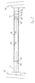
- FIG. 1 is the frame of a seat back in its initial state with the crosspiece of the present invention in place;
- FIG. 2 is an enlarged longitudinal cross-section through the crosspiece of FIG. 1;
- FIG. 3 is a longitudinal cross-section through the crosspiece of FIG. 1 partially deformed as the result of an impact as a result of a crash;
- FIG. 4 is an enlarged sectional view of the left side of the crosspiece of FIG. 3;
- FIG. 5 is an enlarged sectional view of the right side of the crosspiece of FIG. 3;
- FIG. 6 is a longitudinal cross-section through the completely deformed crosspiece of FIG. 1 .
- FIG. 1 shows a frame 1 of a seat back onto which a headrest 2 is secured in a manner well known and not shown in detail.
- the frame 1 includes an upper transverse spar 1 a and a lower transverse spar 1 b that are connected with each other by means of two lateral spars 1 c and 1 d .
- a crosspiece formed of two tubes 3 and 4 extends between the lateral spars 1 c and 1 d .
- the crosspiece is firmly connected with the lateral spars 1 c and 1 d by means of flanges 5 .
- the crosspiece is arranged horizontally and parallel to the transverse spars 1 a and 1 b .
- the crosspiece itself may also be formed by a transverse spar of the frame 1 .
- the tube 3 has an outer diameter corresponding to that of the inner diameter of the tube 4 , and is surrounded for part of its length by tube 4 .
- the tube 3 has one end secured to the lateral spar 1 d .
- the tube 4 is firmly connected to the lateral spar 1 c on the opposite side.
- both tubes 3 and 4 are at an equal distance from their respective lateral spars 1 c and 1 d to which they are not connected.
- tube 4 On its upper side, tube 4 includes two notches 4 a and 4 b that are separated.
- the tube 3 also possesses notches 3 a and 3 b that are in a common vertical plane with notches 4 a or 4 b in its initial position.
- the separation of the notches 3 a or 4 a from notches 3 b or 4 b is the same as the distance between the lateral spars 1 c or 1 d and the free ends of the tube 3 or 4 .
- a surrounding notch or corrugation 4 c is provided at the end of the tube 4 that fits into a notch or corrugation 3 c in tube 3 .
- the tube 3 has a surrounding notch or corrugation 3 d near its end into which a notch or corrugation 4 d fits.
- the tube 4 includes further surrounding notches or corrugations 4 e , 4 f , and 4 g parallel to each other between the corrugation 4 d and the flange 5 .
- the corrugations 4 e , 4 f , and 4 g are not engaged with the tube 3 in the initial position.
- the tube 4 is forced further over tube 3 (as shown in FIG. 3 ).
- the notches 4 c and 4 b and the surrounding corrugations 4 c and 4 d must first be expanded.
- the corrugations 4 e , 4 f , and 4 g are sequentially also expanded.
- kinetic energy is transformed into harmless deformation energy.
- the impact energy is damped by the friction between the tubes 3 and 4 by means of the friction between the corrugations 4 c through 4 g and the outer surface of the tube 3 .
- the notch 4 b is located even with the notch 3 a .
- the bending resistance of the tube connection is thereby weaker at this point than that of the rest of the tube.
- the tubes 3 and 4 will thus bend out at the notched location 3 a / 4 b when a threshold value is exceeded, as FIG. 6 shows. This bending occurs in the direction determined by the notches 3 a and 4 b since the notches pass over only a portion of the overlap between tubes 3 and 4 , thus the bending resistance is weakened only in one direction.
Landscapes
- Engineering & Computer Science (AREA)
- Aviation & Aerospace Engineering (AREA)
- Transportation (AREA)
- Mechanical Engineering (AREA)
- Seats For Vehicles (AREA)
Abstract
Description
Claims (11)
Applications Claiming Priority (3)
| Application Number | Priority Date | Filing Date | Title |
|---|---|---|---|
| DE10029551A DE10029551C1 (en) | 2000-06-15 | 2000-06-15 | Frame, for vehicle seat, has transverse strut that shortens longitudinally if it is loaded, but bends away from support surface at kink point if load exceeds limiting value |
| DE10029551.7 | 2000-06-15 | ||
| DE10029551 | 2000-06-15 |
Publications (2)
| Publication Number | Publication Date |
|---|---|
| US20010052724A1 US20010052724A1 (en) | 2001-12-20 |
| US6523893B2 true US6523893B2 (en) | 2003-02-25 |
Family
ID=7645865
Family Applications (1)
| Application Number | Title | Priority Date | Filing Date |
|---|---|---|---|
| US09/846,594 Expired - Fee Related US6523893B2 (en) | 2000-06-15 | 2001-05-01 | Vehicle seat frame |
Country Status (2)
| Country | Link |
|---|---|
| US (1) | US6523893B2 (en) |
| DE (1) | DE10029551C1 (en) |
Cited By (12)
| Publication number | Priority date | Publication date | Assignee | Title |
|---|---|---|---|---|
| US6880890B1 (en) | 2004-02-05 | 2005-04-19 | Fisher Dynamics Corporation | Multi-position headrest for vehicle seat |
| US20050156456A1 (en) * | 2004-01-16 | 2005-07-21 | Robinson David L. | Vehicle seat headrest adjustment apparatus |
| US20060038428A1 (en) * | 2004-08-17 | 2006-02-23 | Hyundai Mobis Co., Ltd. | Lateral stiffness reinforcement device of vehicle body |
| US20080100104A1 (en) * | 2004-12-20 | 2008-05-01 | Autoliv Development | Seat Back Support Mechanism |
| US20090134682A1 (en) * | 2005-08-30 | 2009-05-28 | Toyota Boshoku Kabushiki Kaisha | Seat reclining device |
| US20110057487A1 (en) * | 2009-09-07 | 2011-03-10 | Mazda Motor Corporation | Seat structure of vehicle |
| US20110193378A1 (en) * | 2010-02-11 | 2011-08-11 | Nissan Technical Center North America, Inc. | Impact absorption block for vehicle seatback assembly |
| US20130119721A1 (en) * | 2011-11-15 | 2013-05-16 | Toyota Boshoku Kabushiki Kaisha | Vehicle seat |
| US8936312B2 (en) | 2010-09-14 | 2015-01-20 | Basf Se | Energy absorbing seat for a vehicle |
| US20150306989A1 (en) * | 2012-11-19 | 2015-10-29 | Ts Tech Co., Ltd. | Seat for vehicle |
| EP3315354A1 (en) | 2016-10-26 | 2018-05-02 | Volvo Car Corporation | An end part and a cross member for a vehicle seat |
| US20180339620A1 (en) * | 2017-05-26 | 2018-11-29 | Toyota Boshoku Kabushiki Kaisha | Vehicle seat |
Families Citing this family (11)
| Publication number | Priority date | Publication date | Assignee | Title |
|---|---|---|---|---|
| GB0315495D0 (en) * | 2003-07-02 | 2003-08-06 | Macliver Kevin S | Childrens safety seat |
| DE102004044734A1 (en) * | 2004-09-15 | 2006-03-16 | Bayerische Motoren Werke Ag | Vehicle e.g. passenger car, seat, has rest and seat frames including two longitudinal chassis beams and two cross beams, where cross beams are made from light metal and chassis beams are made from ferrous material |
| FR2878197B1 (en) * | 2004-11-22 | 2007-01-19 | France Design Sa | SEAT OF A MOTOR VEHICLE FIT TO ABSORB THE ENERGY OF A SIDE SHOCK AGAINST THE VEHICLE |
| US7396065B2 (en) | 2005-11-23 | 2008-07-08 | Heuliez | Automotive vehicle seat for absorbing side impact energy |
| JP5498946B2 (en) * | 2008-09-01 | 2014-05-21 | テイ・エス テック株式会社 | Seat frame and vehicle seat |
| JP2013103674A (en) * | 2011-11-16 | 2013-05-30 | Toyota Boshoku Corp | Vehicle seat |
| EP3144179B1 (en) * | 2014-05-12 | 2020-01-29 | Delta Tooling Co., Ltd. | Seat structure |
| DE102015205231A1 (en) * | 2015-03-23 | 2016-09-29 | Volkswagen Aktiengesellschaft | Side panel of a vehicle seat with a deformation zone |
| FR3039793B1 (en) * | 2015-08-05 | 2017-09-15 | Expliseat | DEFORMABLE SEAT FOR VEHICLE |
| JP6785206B2 (en) * | 2017-09-25 | 2020-11-18 | 株式会社タチエス | Vehicle seat |
| JP7028107B2 (en) * | 2018-08-31 | 2022-03-02 | トヨタ紡織株式会社 | Seat frame |
Citations (3)
| Publication number | Priority date | Publication date | Assignee | Title |
|---|---|---|---|---|
| US3544164A (en) * | 1967-07-24 | 1970-12-01 | Toyota Motor Co Ltd | Seat frame construction |
| US4192545A (en) * | 1977-09-29 | 1980-03-11 | Honda Giken Kogyo Kabushiki Kaisha | Seat-back frame for an automotive vehicle |
| US5681081A (en) * | 1995-10-30 | 1997-10-28 | Mercedes-Benz Ag | Vehicle seat |
Family Cites Families (2)
| Publication number | Priority date | Publication date | Assignee | Title |
|---|---|---|---|---|
| JPH11105602A (en) * | 1997-10-08 | 1999-04-20 | Toyota Motor Corp | Vehicle seat |
| DE19839519B4 (en) * | 1998-08-29 | 2004-07-29 | Daimlerchrysler Ag | cabin |
-
2000
- 2000-06-15 DE DE10029551A patent/DE10029551C1/en not_active Expired - Fee Related
-
2001
- 2001-05-01 US US09/846,594 patent/US6523893B2/en not_active Expired - Fee Related
Patent Citations (3)
| Publication number | Priority date | Publication date | Assignee | Title |
|---|---|---|---|---|
| US3544164A (en) * | 1967-07-24 | 1970-12-01 | Toyota Motor Co Ltd | Seat frame construction |
| US4192545A (en) * | 1977-09-29 | 1980-03-11 | Honda Giken Kogyo Kabushiki Kaisha | Seat-back frame for an automotive vehicle |
| US5681081A (en) * | 1995-10-30 | 1997-10-28 | Mercedes-Benz Ag | Vehicle seat |
Cited By (22)
| Publication number | Priority date | Publication date | Assignee | Title |
|---|---|---|---|---|
| US20050156456A1 (en) * | 2004-01-16 | 2005-07-21 | Robinson David L. | Vehicle seat headrest adjustment apparatus |
| US6880890B1 (en) | 2004-02-05 | 2005-04-19 | Fisher Dynamics Corporation | Multi-position headrest for vehicle seat |
| US20060038428A1 (en) * | 2004-08-17 | 2006-02-23 | Hyundai Mobis Co., Ltd. | Lateral stiffness reinforcement device of vehicle body |
| US7104592B2 (en) * | 2004-08-17 | 2006-09-12 | Hyundai Mobis Co., Ltd. | Lateral stiffness reinforcement device of vehicle body |
| US20080100104A1 (en) * | 2004-12-20 | 2008-05-01 | Autoliv Development | Seat Back Support Mechanism |
| US7854477B2 (en) * | 2004-12-20 | 2010-12-21 | Autoliv Development Ab | Seat back support mechanism |
| US20090134682A1 (en) * | 2005-08-30 | 2009-05-28 | Toyota Boshoku Kabushiki Kaisha | Seat reclining device |
| US7699397B2 (en) * | 2005-08-30 | 2010-04-20 | Toyota Boshoku Kabushiki Kaisha | Seat reclining device |
| US20110057487A1 (en) * | 2009-09-07 | 2011-03-10 | Mazda Motor Corporation | Seat structure of vehicle |
| US8172320B2 (en) * | 2010-02-11 | 2012-05-08 | Nissan North America, Inc. | Impact absorption block for vehicle seatback assembly |
| US20110193378A1 (en) * | 2010-02-11 | 2011-08-11 | Nissan Technical Center North America, Inc. | Impact absorption block for vehicle seatback assembly |
| US8936312B2 (en) | 2010-09-14 | 2015-01-20 | Basf Se | Energy absorbing seat for a vehicle |
| US8955906B2 (en) | 2010-09-14 | 2015-02-17 | Basf Se | Energy absorbing bracket for a seat of a vehicle |
| US9434281B2 (en) | 2010-09-14 | 2016-09-06 | Basf Se | Energy absorbing seat for a vehicle |
| US20130119721A1 (en) * | 2011-11-15 | 2013-05-16 | Toyota Boshoku Kabushiki Kaisha | Vehicle seat |
| US8833850B2 (en) * | 2011-11-15 | 2014-09-16 | Toyota Boshoku Kabushiki Kaisha | Vehicle seat |
| US20150306989A1 (en) * | 2012-11-19 | 2015-10-29 | Ts Tech Co., Ltd. | Seat for vehicle |
| US9415709B2 (en) * | 2012-11-19 | 2016-08-16 | Ts Tech Co., Ltd. | Seat for vehicle |
| US10023082B2 (en) | 2012-11-19 | 2018-07-17 | Ts Tech Co., Ltd. | Seat for vehicle |
| EP3315354A1 (en) | 2016-10-26 | 2018-05-02 | Volvo Car Corporation | An end part and a cross member for a vehicle seat |
| US20180339620A1 (en) * | 2017-05-26 | 2018-11-29 | Toyota Boshoku Kabushiki Kaisha | Vehicle seat |
| US10442331B2 (en) * | 2017-05-26 | 2019-10-15 | Toyota Boshoku Kabushiki Kaisha | Vehicle seat |
Also Published As
| Publication number | Publication date |
|---|---|
| DE10029551C1 (en) | 2001-10-25 |
| US20010052724A1 (en) | 2001-12-20 |
Similar Documents
| Publication | Publication Date | Title |
|---|---|---|
| US6523893B2 (en) | Vehicle seat frame | |
| US6371541B1 (en) | Energy absorbing device | |
| US6938948B1 (en) | Energy absorbing front frame structure for a vehicle | |
| JP5121677B2 (en) | Shock absorbing member | |
| KR101445149B1 (en) | Seat assembly having an impact load transfer structure | |
| US6851731B2 (en) | Crash energy absorbing element | |
| CN101108633B (en) | Car with load-bearing structure with longitudinal and cross members | |
| JP2012107660A (en) | Energy absorber, collision energy absorbing structure having the same, and railroad vehicle having the collision energy absorbing structure | |
| US7275764B2 (en) | Vehicle occupant knee protection device | |
| KR20100061288A (en) | Crash energy absorber absorbing crash energy by stages | |
| US9840221B2 (en) | Grab handle bracket | |
| US6837518B2 (en) | Reinforcement structure for instrument panel | |
| US8353545B1 (en) | Compact energy absorbing vehicle crash structure | |
| EP1679234B1 (en) | Impact energy absorbing structure for vehicle | |
| US20100259036A1 (en) | Variable load knee bolster | |
| JPH0575057U (en) | Shock absorption type steering column device | |
| EP3647109B1 (en) | Pivot bracket for connecting vehicle seats | |
| US11052848B2 (en) | Energy absorbing device | |
| US10640080B2 (en) | Safety belt including plate-type load limiter | |
| JP2009056945A (en) | Bumper device for vehicle | |
| JP4473537B2 (en) | Energy absorber for personal protection | |
| JP2009107445A (en) | Body front structure | |
| CN112672926B (en) | Energy absorber, motor vehicle body and method for producing an energy absorber | |
| JPH0872543A (en) | Car door guard bar | |
| KR100412455B1 (en) | Roof rear rail reinforcement structure for automobile |
Legal Events
| Date | Code | Title | Description |
|---|---|---|---|
| AS | Assignment |
Owner name: FAURECIA AUTOSITZE GMBH & CO., KG, GERMANY Free format text: ASSIGNMENT OF ASSIGNORS INTEREST;ASSIGNORS:KAMPER, RALF;KIESLMEIER, NORBERT;REEL/FRAME:011771/0835 Effective date: 20010419 |
|
| FPAY | Fee payment |
Year of fee payment: 4 |
|
| FEPP | Fee payment procedure |
Free format text: PAYOR NUMBER ASSIGNED (ORIGINAL EVENT CODE: ASPN); ENTITY STATUS OF PATENT OWNER: LARGE ENTITY |
|
| FPAY | Fee payment |
Year of fee payment: 8 |
|
| REMI | Maintenance fee reminder mailed | ||
| LAPS | Lapse for failure to pay maintenance fees | ||
| STCH | Information on status: patent discontinuation |
Free format text: PATENT EXPIRED DUE TO NONPAYMENT OF MAINTENANCE FEES UNDER 37 CFR 1.362 |
|
| STCH | Information on status: patent discontinuation |
Free format text: PATENT EXPIRED DUE TO NONPAYMENT OF MAINTENANCE FEES UNDER 37 CFR 1.362 |
|
| FP | Lapsed due to failure to pay maintenance fee |
Effective date: 20150225 |