US652138A - Lawn-mower. - Google Patents
Lawn-mower. Download PDFInfo
- Publication number
- US652138A US652138A US72110699A US1899721106A US652138A US 652138 A US652138 A US 652138A US 72110699 A US72110699 A US 72110699A US 1899721106 A US1899721106 A US 1899721106A US 652138 A US652138 A US 652138A
- Authority
- US
- United States
- Prior art keywords
- bar
- finger
- fingers
- knife
- cutter
- Prior art date
- Legal status (The legal status is an assumption and is not a legal conclusion. Google has not performed a legal analysis and makes no representation as to the accuracy of the status listed.)
- Expired - Lifetime
Links
Images

Classifications
-
- A—HUMAN NECESSITIES
- A01—AGRICULTURE; FORESTRY; ANIMAL HUSBANDRY; HUNTING; TRAPPING; FISHING
- A01D—HARVESTING; MOWING
- A01D34/00—Mowers; Mowing apparatus of harvesters
- A01D34/01—Mowers; Mowing apparatus of harvesters characterised by features relating to the type of cutting apparatus
- A01D34/02—Mowers; Mowing apparatus of harvesters characterised by features relating to the type of cutting apparatus having reciprocating cutters
Definitions
- the invention consists in certain novel features of construction and in combinations and arrangements and details of parts, as more fully and particularly set forth and described hereinafter.
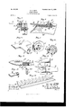
- Figure 1 is a side elevation of the lawn-mower with parts broken away.
- Fig. 2 is a top plan view, parts beingbroken away.
- Fig. 3 is a longitudinal sectional view on line 3 3, Fig.
- Fig. 4 is a sectional view on the line 4 at, Fig. 2.
- Fig. 5 is a cross-sectional view on the line 5 5, Fig. 2, showing the means employed in mounting the oscillating lever on the cross-bar of the frame.
- Fig. 6 is a detail perspective view of a portion of the cross-bar of the frame, the oscillating lever being re moved.
- Figs. 7 and 8 are detached detail views'illustrating the ratchet mechanism between a driving-wheel and the actuating camshaft.
- Fig. 9 is a cross-section on the line 9 9, Fig. 2, illustrating the manner of securing the front ends of the side frames to the fingerbar.
- Fig. 10 is an enlarged sectional view on line 10 10, Fig. 2.
- Fig. 10 is an enlarged sectional view on line 10 10, Fig. 2.
- Fig. 11 is a detail perspective of one of the spring-keepers.
- Fig. 12 shows the finger-bar blank in the rough as cast or formed by' drop-forging or otherwise and before the method is carried out to the completionof the finger-bar ready to receive the knife-bar.
- Fig. 13 is a bottom plan of a portion of the finger-bar, showing the ribs on the bottom thereof formed to receive the front end of a side frame.
- Fig. lat is a detail perspective of the pawl in a ratchet mechanism.
- Fig. 15 is a detail perspective of the rear end of the lever, showing the loose roller thereon.
- a a are the side frames of the machine, at their front ends rigidly secured together by a finger orguard bar Z) and at intermediate points secured together by the cross-bar c and at their rear portions secured together or connected by what might be termed an axle d, but which is, in effect, a tie rod or bolt, and also by a camwheel shaft 6.
- the rear end of each side frame is in the form of an enlarged verticallydisposed flat disk a, having the central outwardly-projecting boss a formed integral therewith.
- the axle or rod cl projects through said disks and through and beyond the bosses and is provided with screw-threaded projecting ends.
- the disks are provided with openings and surrounding bearings receiving a cam-shaft 6, extending between the disks, with its ends extending through said bearings and projecting beyond the outer faces of the disks.
- This shaft has a grooved cam-wheel f mounted centrally and rigidly thereon.
- This cam-wheel can be of any suitable and desirable construction, and the invention is not limited to thespecific cam-wheel shown, wherein the rim of the wheel has the peripheral groove and is deflected laterally alternately in opposite directions.
- the cam-wheel can be cast integral with the rim carried by spokes from a central hub. The hub is shown fitted on the shaft and locked thereon by set-screws.
- Each wheel has a rim formed of the annular inwardly-extend in g flange surrounding the edge of the frame-disk and of sufficient depth to leave a space between the vertical portion of the wheel and the frame-disk.
- Each wheel has an inwardly-projecting hub surrounding and turning on the boss of the frame-disk, and the wheels are confined in position by nuts 61 at the outer facesthereof and screwedon the projecting ends of the aXle.'
- Theouter periphery of the rim of each wheel is suitably formed to attain the proper traction with the sod as the machine is moved, and each rim is provided with a narrow integral gear h, 10-
- cam-wheel shaft are geared with the internal gearing of said drive-wheels through the medium of a suitable ratchet mechanism, which causes the said shaft to rotate with the drive-wheels as the machine'is moved forward, but which allow the-drive-wheels to rotate freely in the oppo- 1 ing outwardly from its outer face.
- j is a pinion-in constant mesh with the integral gearing of the drive-wheel.
- This pinion is mounted loosely on the end of the camshaft and is formed with an inward extension j beyond the gear-teeth thereof and at its inner end abuts against the said disk 2'.
- This extension of the pinion c is provided with a circular end recess or socket 3' concentric with the cam-shaft and receiving said ratchet wheel or teeth 2' on the said disk, so that said ratchet-wheel is inclosed within the end extension of the pinion, and said extension of the pinion and the disk iare both located opposite or just within the smoothfaced portion of the rim of the drive-wheel and inwardly beyond the internal gearing and pinion-teeth.
- the extended end-of the pinion is providedwith a radial groove, slot, or recess j opening into the end recessj and extending through the periphery of said extension.
- a tangentially-arranged plate-spring k is secured at the exterior of the extended end of the pinion, with its inwardly-pressing free end located over said openingj and engaging and constantly forcing inwardly the block I, radially located and movable in and through said opening and having an inner beveled end arranged to ride on the ratchetteeth.
- the said block,- which forms a pawl, projects a sufficient distance into the said end recess to lock the pinion to the ratchet-wheel when the machine is moving forward and to ride loosely over the ratchet-teeth and reciprocate longitudinally without turning the pinion when the machine moves rearwardly.
- This construction is of the utmost simplicity and durability.
- the parts can be cast or otherwise made at a minimum cost.
- the ratchet mechanism is inclosed, and dirt is consequently kept therefrom.
- the pawl is not secured, and hence can be removed and replaced most conveniently and easily, and the construction is otherwise of the highest efficiency andadvantage.
- each side frame extends horizontally forwardly from its end disk and is deflected inwardly at its junction with the disk.
- the arm or forwardly-extending portion of each side frame has the bottom horizontal flange a projecting laterally on both sides of the vertical web of the frame.
- the outer sides of the side frames are formed with lateral enlargements M, the outer vertical faces of which are approximately flush with the outer edges of the flanges er
- the ends of the radial arms n are secured against the outer faces of said seats or enlargements by transverse bolts 02, passing through the arms, enlargements, and side frames and provided with clamping-nuts at the inner faces of the side frames.
- the radial arms preferably extend forwardly from their pivoted ends and have outwardly-extending horizontal spindles, on which the small gage-rollers 0 are mounted and confined.
- the vertical position of the finger-bar is determined by the vertical adjustment of said rollers, which is effected by loosening clamping-bolts n and swinging the radial arms up or down the desired distance and then clamping the arms in the desired position.
- the enlargements of the frame sides carry the radial arms out beyond the vertical planes of the bottom flanges of the side frames, and the inward offsets or deflections of the side frames before described cause the d rive-wheels to track with said gage rollers.
- the finger-bar b is formed integral with its guards or fingers, as hereinafter set forth, and the ribs or flanges Z) are continued transversely across the bottom face of the bar in continuation of the under edges of the respective fingers.
- each side frame is at the front end a extended beneath and transversely of the cutter-bar and formed to fit snugly between two of said ribs b and thereby most strongly brace the parts against independent lateral play or looseness, while the said ends a are rigidly secured to the finger-bar by vertical screws, rivets, or the like passed through said parts.
- each side frame is later ally enlarged and arranged vertically to abut against the rear edge of the finger-bar.
- p is the reciprocating knife-bar in the finger-bar and at its central portion is provided with the upwardly-projectingeye p, rigid therewith.
- q is the oscillating lever between the camwheel and the knife-bar.
- the lever is mounted or fulcrumed on the crossbar 0 between the side frames.
- the cross-bar is provided with angular or downwardly-projected vertical ends 0, at their lower ends rested and seated on the bottom flanges (t of the frame sides, and thereby strongly bracing the structure and holding the cross-bar against tilting.
- the cross-bar is secured to the frame sides by horizontal bolts or other fastening means passed through said vertical ends 0 and the vertical webs of the side frames.
- the crossbar is provided with a central forwardly-projecting lip or ear 0 formed integral with the bar and having a centrally disposed upwardly-projecting boss a integral therewith.
- This boss is cylindrical and is of greater length than the thickness ot'the lever g, which has an opening through which the boss projects and on which the lever is fulcrumed.
- the lever is loosely confined against displacement by a washer or cap 0 held down on the upper end of the boss by a bolt 0 passed down through the cap, boss, and cross-bar and secured by a nut on its lower end.
- the groove is less than the width of the bar and is so arranged as to be always covered by the lever in its path of movement.
- the upper end of said lever is reduced to a spindle projecting within the groove of the camwheel and having a loose roll q located thereon and fitted in said groove.
- the front end of said oscillating lever is usually reduced and inserted loosely in the eye 1), rigid with the knife-bar, whereby the lever oscillated by the cam-wheel thereby rapidly reciprocates the knife-bar.
- the finger-bar is provided with a slideway or groove 1) in its top face, longitudinally thereof and preferably open at the ends. This. groove is preferably located near the front edge of the bar and adjacent to the junctions between the fingers or guards and the bar.
- the top face of the bar is preferably smooth.
- the knife-bar is composed of a straight bar 19 fitted snugly in the groove Z1 and in crosssection conforming to the groove in cross-section.
- the groove and bar are preferably rectangular in cross-section, and the upper edge of the bar 13 is usually flush with the top face of the finger-bar.
- the flat knives p are secured ri idly on the top edge of the bar 19 and project forwardly therefrom.
- Each knife is preferably of the usual triangular form.
- the knives preferably, do not project rearwardly beyond bar 19 but extend horizontally forward in the slots through the fingers.
- the knives are beveled down on their top faces to the side cutting edges to cooperate with the side cutting edges of the guards or fingers in performing the shearing cut.
- the knife-bar is so much shorter in length than the finger-bar that the path of reciprocation of the knife-bar does not project it beyond the ends of the finger-bar.
- the finger-bar has eleven equally-spaced fingers the knife-bar usually has ten knives.
- the end fingers of the finger-bar are located inwardly certain distances from the ends of the bar, and the bar is formed integral with horizontal webs b extending from the outer edges of the points of the end fingers to the front edge of the outer ends of the finger-bar.
- the outer edges of these webs are inclined rearwardly and outwardly, and the top faces of the webs are depressed below the top face of finger-bar and below the bottoms of the grooves through the end fingers.
- the end webs protect the end knives against injurious contact with obstructions and also protect the end fingers and the ends of the finger-bar.
- the horizontal grooves through the fingers are in vertical width greater than the thickness of the knives located therein and sliding back and forth on the floors thereof, and the bar or body 17 of the knife-bar rests loosely in and can be lifted from the slidewayin the finger-bar.
- Suitable means are provided to yieldingly confine the knife-bar in position and down to its work.
- I show and usually employ spring-keepers s s, engaging the knife-bar at points intermediate the lengths of the knives and intermediate the lengths of the cutting edges thereof and over the cutting edges of the finger-bar.
- Each keeper is shown formed of a piece of thin spring sheet metal, with the flat portion secured on the top face of the finger-bar in rear of the knife-bar by suitable fastening means, such as screw 3, and the Wide springmetal plate is deflected or bent upwardly from its flat base and extended forwardly above and out of contact with the knife-bar.- The front end of the plate is deflected downwardly into engagement with the knives over the cutting edges of the finger-bar and at points about midway of the lengths of the cutting edges of the knives.
- I show two such keepers located near opposite ends of the finger-bar; but the invention is not so limited.
- the upwardly-bulged portions of the keepers over the rear of the knife-bar permits limited upward play thereof, although such movement of the knife-bar is in a measure against the tension of the free ends of the keepers, and the rear edges of the knives will engage the rear portions of the keepers when the limit of movement is reached.
- the free ends of the keepers press down with considerable force on the knives, the free end of akeeper usually alternating, engaging two knives as the knife-bar reciprocates, and the cutting edges of the knives are thus held down to the cutting edges of the finger-bar with a yielding pressure, whereby most material and important advantages are attained and wear is taken up and the shearing edges constantly kept together for the performance .of their properfunctions.
- astheknifebar is held by a yielding pressure it can lift at the front or rear or either end or bodily throughout to clear itself of obstructions working between the shearing edges.
- my spring-keeper is tapered forwardly and projects over the cutter-bar and presses down on the knives thereof directly over the cutting edges of the knives and finger-bar. Peculiar new results are attained by thus locating the springkeepers, and the inclined or beveled edges thereof permit the grass to pass back between the knives to the extreme rear portions of the cutting edges thereof.
- the spring-keepers can be easily removed and replaced and are exceedingly economical in structure and use and reduce wear of the parts to a minimum, and peculiar advantages are attained by employing these spring-keepers in connection with my finger-bar.
- the finger-bar shown I first form the blank for bar and its fingers or guards in the rough in one integral piece.
- the bar can be thus formed by drop-forging, casting, or molds or otherwise.
- the bar is formed with the transverse body thereof solid and flat at the top and with the bottom ribs, and the guards or fingers are also formed solid, with their upwardly-projecting portions extending back approximately to the transverse body of the bar.
- a suitable machine or tool mill or otherwise cut the groove or slideway in the top face of the bar to receive the knife-bar. While this operation is being performed, the rough blank is held rigidly and the groove is out perfectly true and parallel with the edges of the bar and of the same depth throughout.
- the blank is then locked or held rigidly in a vertical position or on edge on the points of the fingers, and arapidly-driven saw or other suitable implement cuts the grooves through and longitudinally of the fingers and the face of the bar from the front edge of the slideway forwardly perfectly level and smooth and to the same horizontal plane as the floors of the grooves through the fingers.
- the finger-bar is then properly held and the adjacent side faces of the fingers from the front edge of the bar out to the front ends of the grooves are ground down, thereby forming perfect cutting and shearing edges at the sides of the fingers where the floors of the grooves end.
- the bar is thus complete and ready to receive the knife-bar.
- My cutter-bar is not limited to employment in lawn-mowers constructed in accordance with other features stated, and the same is true of the spring-keepers and other separate features of my invention, although according to my present experiments I use all the IIO various features of my invention in a machine substantially as shown; but it is ob vious that various changes and modifications might be made in the forms, constructions, and arrangements of the parts described without departing from the spirit and scope of my invention. Hence I do not wish to limit myself to all the features exactly as shown and described.
- a framework driving-wheels
- the finger-bar having ribs extended transversely across its bottom in continuation of the fingers,the front ends of the framework fitting under said bar between certain of said ribs and secured to said bar and abutting against the rear edge thereof, said bar-formed in one piece with its iingers and having the longitudinal top groove, the fingers having slots cut therein, the face of the finger-bar in advance of said groove and forming the floor of said slots ground true and in one plane, the cutter-bar sliding in said groove and having its knives resting on said true-plane face, and actuating mechanism for reciprocating said knife-bar, substantially as described.
- a lawn-mower the combination of a frame, driving means, actuating means for the cutting mechanism, the cutting mechanism comprising the'finger-bar, and the cutterbar reciprocating therein and having vertical play, and spring-keepers secured to the fingerbar and arched over the cutter-bar with their front ends yieldingly pressing down on the cutter-bar over the cutting portions thereof and yieldingly holding the cutter-bar down on the finger-bar and permitting the vertical play of the cutter-bar, said finger-bar and its fingers formed integral and having a longitudinal Way out in its upper face and receiving the cutter-bar, the fingers of said bar having slots cut therein all in the same plane, the floors of said slots and the face of the cutter-bar in advance of said way being ground true and in the same plane and receiving the knives of the cutter-bar, the sides of the fingers being ground and forming knife-edges at the edges of said faces forming the floors of said finger-slots,substantially as described.
- a lawn-mower the combination of a framework, a finger-bar rigidlysecured thereto and having a longitudinal groove in its u p per face in rear of the fingers, a reciprocating cutter-bar sliding in said groove with its knives receiprocating over the cutting edges of the fingers, said cutter-bar having a limited vertical play, and the spring-keepers yieldinglyholding the cutter-bar down on the fingers and upper face of the finger-bar, each keeper formed of thin spring metal and secured to the finger-bar in rear of the cutterbar and arched up over the cutter-bar and having its front end deflected down into engagement with a knife or knives of the cutter-bar over the cooperating cutting portions of the finger-bar, substantially as described.
- a lawn-mower the combination of a framework, ground-wheels, actuating mechanism for the cutter mechanism, a finger-bar secured to the framework and havingits longitudinal portion formed with a longitudinal groove in rear of. the fingers, the reciprocating cutter-bar having limited vertical play and comprising the bar sliding in said groove and the flat knife-sections seen red thereto and sliding over the shearing edges of the fingers, and separate spring-keepers, each keeper secured to the finger-bar in rear of said cutter-bar and projecting close over the rear portion of said cutter-bar, for the pur pose described, and deflected up over the cut ter-bar and engaging the knife-sections over and holding the same yieldingly down to the cod perating shearing edges of the fingers, sub stantially as described.
- the combination of side frames, ground-wheels, and actuating mechanism the finger-bar formed integral from a single blank with the ribs extended across its under surface and having a flat longitudinally grooved top surface, the slots cut through the fingers and all located in the same plane, the front ends of the side frames fitted between certain of said ribs and abutting against the edge of and secured to the bar, a reciprocating cutter-bar fitted to the fingerbar, and spring-keepers secured to the fingerbar and pressing down on certain knife-sections thereof as described.
- a lawn-mower the combination of a frame, and driving mechanism, with a cutting mechanism comprising a finger-bar,a cutter-bar reciprocating thereon and having limited vertical play,and independent forwardlytapering spring-keepers secured to the finger bar and extending forwardly over the cutterbar and yieldingly bearing down only on certain knife-sections of the cutter-bar over the cooperatin g cutting portions of the finger-bar, as and for the purpose set forth.
- a frame driving means, mechanism for reciprocating the cutter-bar, the cutting mechan ism comprising a finger-bar, and the cutter bar reciprocating therein and having vertical play, and spring-keepers secured to the fingerbar and arched over the cutter-bar With their ends yieldingly pressing down on the cutterbar 'over the cutting portions thereof and yieldingly holding the cuttei bar down on the finger-bar and permitting the vertical play of the cutter-bar, substantially as described.
- thefinger-bar having limited vertical movement and fitting said groove with its knife-sections resting on the fiat face of the bar in advance of the'groove, and the isolated spring-keepers, each having a flat end resting on the top face of the finger-bar at the rear edge of the cutter-bar, a securing-screw passing through said flat end into the fingerbar, said keeper arched upwardly and forwardly and downwardly from said flat end With its front end resting and yieldingly hearing down on a knife-section of said cutterbar, substantially as described.
- each pinion loose on said shaft ends, at their outer ends abutting against said wheels and at their inner ends abutting against said disks, each pinion having the exteriorlysmooth-faced inner end formed with aconcenteeth, and the inner end radial opening, the removable slide-block in said opening, and the plate-spring circumferentially arranged on said smooth-faced portion with its free end engaging the outer end of said block, substantially as described.
Description
No. 652,l38. Patented June l9, I900.
R. K; ORTT. LAWN MOWER.
(Application filed June 19, 1899.)
2 Sheets-sheaf I.
(No Model.)
THE ripnms PETERS co, wcmumou WASHINGTON. ov cv No. 652,!38. Patented lune I19, I900.
R. K. DBTT;
LAWN MOWER.
(Application filed June 19, 1899.)
(No Model.) 2 Sheets-$haet 2.
' 7Z1 u/ C ulll V/llll UNITED STATES.
PATENT O FICE.
ROWLEY K. onrr, or NORRISTOWN,PENNSYLVANIA.
LAWN- MOWER.
SPECIFICATION forming part of Letters Patent No. 652,138, dated June 19, 1900. Application filed J'unelil, 1899- Serial No. 721,106; (No model.)
To all whom. it nut/y concern:
Be itknown that I, ROWLEY K. ORTT, a citizen of the United States, residing at Norris town, in the county of Montgomery and State of Pennsylvania, have invented certain new and useful Improvements in Lawn-Mowers; and I do hereby declare the following to be a full, clear, and exact description of the invention, such as will enable others skilled in the art to which it appertains to make and use the same.
This invention relates to certain improvements in lawn-mowers; and the objects and nature of the invention will be fully understood from the following description, considered in connection with the accompanying drawings, forming a part hereof.
The invention consists in certain novel features of construction and in combinations and arrangements and details of parts, as more fully and particularly set forth and described hereinafter.
Referring to the accompanying drawings, Figure 1 isa side elevation of the lawn-mower with parts broken away. Fig. 2 is a top plan view, parts beingbroken away. Fig. 3 is a longitudinal sectional view on line 3 3, Fig.
2. Fig. 4 is a sectional view on the line 4 at, Fig. 2. Fig. 5 is a cross-sectional view on the line 5 5, Fig. 2, showing the means employed in mounting the oscillating lever on the cross-bar of the frame. Fig. 6 is a detail perspective view of a portion of the cross-bar of the frame, the oscillating lever being re moved. Figs. 7 and 8 are detached detail views'illustrating the ratchet mechanism between a driving-wheel and the actuating camshaft. Fig. 9 is a cross-section on the line 9 9, Fig. 2, illustrating the manner of securing the front ends of the side frames to the fingerbar. Fig. 10 is an enlarged sectional view on line 10 10, Fig. 2. Fig. 11 is a detail perspective of one of the spring-keepers. Fig. 12 shows the finger-bar blank in the rough as cast or formed by' drop-forging or otherwise and before the method is carried out to the completionof the finger-bar ready to receive the knife-bar. Fig. 13 is a bottom plan of a portion of the finger-bar, showing the ribs on the bottom thereof formed to receive the front end of a side frame. Fig. lat is a detail perspective of the pawl in a ratchet mechanism. Fig. 15 is a detail perspective of the rear end of the lever, showing the loose roller thereon.
In the drawings, a a are the side frames of the machine, at their front ends rigidly secured together by a finger orguard bar Z) and at intermediate points secured together by the cross-bar c and at their rear portions secured together or connected by what might be termed an axle d, but which is, in effect, a tie rod or bolt, and also by a camwheel shaft 6. The rear end of each side frame is in the form of an enlarged verticallydisposed flat disk a, having the central outwardly-projecting boss a formed integral therewith. The axle or rod cl projects through said disks and through and beyond the bosses and is provided with screw-threaded projecting ends. In rear of said axle the disks are provided with openings and surrounding bearings receiving a cam-shaft 6, extending between the disks, with its ends extending through said bearings and projecting beyond the outer faces of the disks. This shaft has a grooved cam-wheel f mounted centrally and rigidly thereon. This cam-wheel can be of any suitable and desirable construction, and the invention is not limited to thespecific cam-wheel shown, wherein the rim of the wheel has the peripheral groove and is deflected laterally alternately in opposite directions. The cam-wheel can be cast integral with the rim carried by spokes from a central hub. The hub is shown fitted on the shaft and locked thereon by set-screws.
9 represents the driving ground-Wheels arranged at the outer faces of the disks of the side frames and concentric therewith. Each wheel has a rim formed of the annular inwardly-extend in g flange surrounding the edge of the frame-disk and of sufficient depth to leave a space between the vertical portion of the wheel and the frame-disk. Each wheel has an inwardly-projecting hub surrounding and turning on the boss of the frame-disk, and the wheels are confined in position by nuts 61 at the outer facesthereof and screwedon the projecting ends of the aXle.' Theouter periphery of the rim of each wheel is suitably formed to attain the proper traction with the sod as the machine is moved, and each rim is provided with a narrow integral gear h, 10-
cated at the inner portion of the rim, so as to leave the inner face smooth beyond the said gearing. The ends of the cam-wheel shaft are geared with the internal gearing of said drive-wheels through the medium of a suitable ratchet mechanism, which causes the said shaft to rotate with the drive-wheels as the machine'is moved forward, but which allow the-drive-wheels to rotate freely in the oppo- 1 ing outwardly from its outer face.
j is a pinion-in constant mesh with the integral gearing of the drive-wheel. This pinion is mounted loosely on the end of the camshaft and is formed with an inward extension j beyond the gear-teeth thereof and at its inner end abuts against the said disk 2'. This extension of the pinion c is provided with a circular end recess or socket 3' concentric with the cam-shaft and receiving said ratchet wheel or teeth 2' on the said disk, so that said ratchet-wheel is inclosed within the end extension of the pinion, and said extension of the pinion and the disk iare both located opposite or just within the smoothfaced portion of the rim of the drive-wheel and inwardly beyond the internal gearing and pinion-teeth. The extended end-of the pinion is providedwith a radial groove, slot, or recess j opening into the end recessj and extending through the periphery of said extension. A tangentially-arranged plate-spring k is secured at the exterior of the extended end of the pinion, with its inwardly-pressing free end located over said openingj and engaging and constantly forcing inwardly the block I, radially located and movable in and through said opening and having an inner beveled end arranged to ride on the ratchetteeth. The said block,- which forms a pawl, projects a sufficient distance into the said end recess to lock the pinion to the ratchet-wheel when the machine is moving forward and to ride loosely over the ratchet-teeth and reciprocate longitudinally without turning the pinion when the machine moves rearwardly. This construction is of the utmost simplicity and durability. The parts can be cast or otherwise made at a minimum cost. The ratchet mechanism is inclosed, and dirt is consequently kept therefrom. The pawl is not secured, and hence can be removed and replaced most conveniently and easily, and the construction is otherwise of the highest efficiency andadvantage.
mis the handle of the machine, having the yoke at its lower end mounted to swing on the agrle between the end disks. The end disks in rear of the axle are cast or otherwise formed with inwardly-projecting lugs m beneath the yoke and engaging the ends of the yoke and limiting the downward movement of the handle to about the position required in use by the ordinary operator, and yet permitting free upward swing of the handle, the yoke ends then turning on the axle. Each side frame extends horizontally forwardly from its end disk and is deflected inwardly at its junction with the disk. The arm or forwardly-extending portion of each side frame has the bottom horizontal flange a projecting laterally on both sides of the vertical web of the frame. At intermediate points between the finger-bar and the drive-wheels the outer sides of the side frames are formed with lateral enlargements M, the outer vertical faces of which are approximately flush with the outer edges of the flanges er The ends of the radial arms n are secured against the outer faces of said seats or enlargements by transverse bolts 02, passing through the arms, enlargements, and side frames and provided with clamping-nuts at the inner faces of the side frames. The radial arms preferably extend forwardly from their pivoted ends and have outwardly-extending horizontal spindles, on which the small gage-rollers 0 are mounted and confined. The vertical position of the finger-bar is determined by the vertical adjustment of said rollers, which is effected by loosening clamping-bolts n and swinging the radial arms up or down the desired distance and then clamping the arms in the desired position. The enlargements of the frame sides carry the radial arms out beyond the vertical planes of the bottom flanges of the side frames, and the inward offsets or deflections of the side frames before described cause the d rive-wheels to track with said gage rollers.
The finger-bar b is formed integral with its guards or fingers, as hereinafter set forth, and the ribs or flanges Z) are continued transversely across the bottom face of the bar in continuation of the under edges of the respective fingers.
The horizontal bottom or flanged portion of each side frame is at the front end a extended beneath and transversely of the cutter-bar and formed to fit snugly between two of said ribs b and thereby most strongly brace the parts against independent lateral play or looseness, while the said ends a are rigidly secured to the finger-bar by vertical screws, rivets, or the like passed through said parts.
The front end of each side frame is later ally enlarged and arranged vertically to abut against the rear edge of the finger-bar.
p is the reciprocating knife-bar in the finger-bar and at its central portion is provided with the upwardly-projectingeye p, rigid therewith.
q is the oscillating lever between the camwheel and the knife-bar. The lever is mounted or fulcrumed on the crossbar 0 between the side frames. The cross-bar is provided with angular or downwardly-projected vertical ends 0, at their lower ends rested and seated on the bottom flanges (t of the frame sides, and thereby strongly bracing the structure and holding the cross-bar against tilting. The cross-bar is secured to the frame sides by horizontal bolts or other fastening means passed through said vertical ends 0 and the vertical webs of the side frames. The crossbar is provided with a central forwardly-projecting lip or ear 0 formed integral with the bar and having a centrally disposed upwardly-projecting boss a integral therewith. This boss is cylindrical and is of greater length than the thickness ot'the lever g, which has an opening through which the boss projects and on which the lever is fulcrumed. The lever is loosely confined against displacement by a washer or cap 0 held down on the upper end of the boss bya bolt 0 passed down through the cap, boss, and cross-bar and secured by a nut on its lower end. By this construction wear on and cutting of the bolt and tightness on the fulcrum of the lever are avoided, as the bolt can be drawn as tightly as desired without tightening the lever at its fulcrum ,as the washer is merelydrawn against the end of the boss. The large boss receives the wear and sustains the heavy strain and friction, and wear and looseness are reduced to a minimum, and yet the parts can be easily released and removed and replaced.
As the forward rotation of the cam-wheel exerts downward pressure on the rear of the lever and tends to press the same against the cross-bar in rear of the fulcrum and cause friction, wear, and noise, I have found it advantageous to provide an additional bearingpoint and support for the lever at a point between the fulcrum and cam-wheel. To this end I form the cross-bar with a groove or depression 0 in its top face a distance in rear of the lever-fulcrum. This groove has closed ends and is arranged transversely of the lever, and in this groove one or more balls 0 are loosely located, projecting above the top face of the cross-bar and into engagement with the under face of the lever. In length the groove is less than the width of the bar and is so arranged as to be always covered by the lever in its path of movement. The upper end of said lever is reduced to a spindle projecting within the groove of the camwheel and having a loose roll q located thereon and fitted in said groove. The front end of said oscillating lever is usually reduced and inserted loosely in the eye 1), rigid with the knife-bar, whereby the lever oscillated by the cam-wheel thereby rapidly reciprocates the knife-bar.
The finger-bar is provided with a slideway or groove 1) in its top face, longitudinally thereof and preferably open at the ends. This. groove is preferably located near the front edge of the bar and adjacent to the junctions between the fingers or guards and the bar. The top face of the baris preferably smooth.
The knife-bar is composed of a straight bar 19 fitted snugly in the groove Z1 and in crosssection conforming to the groove in cross-section. The groove and bar are preferably rectangular in cross-section, and the upper edge of the bar 13 is usually flush with the top face of the finger-bar. The flat knives p are secured ri idly on the top edge of the bar 19 and project forwardly therefrom. Each knife is preferably of the usual triangular form. The knives, preferably, do not project rearwardly beyond bar 19 but extend horizontally forward in the slots through the fingers. The knives are beveled down on their top faces to the side cutting edges to cooperate with the side cutting edges of the guards or fingers in performing the shearing cut.
The knife-bar is so much shorter in length than the finger-bar that the path of reciprocation of the knife-bar does not project it beyond the ends of the finger-bar. Thus where the finger-bar has eleven equally-spaced fingers the knife-bar usually has ten knives.
The end fingers of the finger-bar are located inwardly certain distances from the ends of the bar, and the bar is formed integral with horizontal webs b extending from the outer edges of the points of the end fingers to the front edge of the outer ends of the finger-bar. The outer edges of these webs are inclined rearwardly and outwardly, and the top faces of the webs are depressed below the top face of finger-bar and below the bottoms of the grooves through the end fingers. The end webs protect the end knives against injurious contact with obstructions and also protect the end fingers and the ends of the finger-bar.
The horizontal grooves through the fingers are in vertical width greater than the thickness of the knives located therein and sliding back and forth on the floors thereof, and the bar or body 17 of the knife-bar rests loosely in and can be lifted from the slidewayin the finger-bar. Suitable means are provided to yieldingly confine the knife-bar in position and down to its work. As an example of simple and effective means for this purpose I show and usually employ spring-keepers s s, engaging the knife-bar at points intermediate the lengths of the knives and intermediate the lengths of the cutting edges thereof and over the cutting edges of the finger-bar. Each keeper is shown formed of a piece of thin spring sheet metal, with the flat portion secured on the top face of the finger-bar in rear of the knife-bar by suitable fastening means, such as screw 3, and the Wide springmetal plate is deflected or bent upwardly from its flat base and extended forwardly above and out of contact with the knife-bar.- The front end of the plate is deflected downwardly into engagement with the knives over the cutting edges of the finger-bar and at points about midway of the lengths of the cutting edges of the knives. In the drawings I show two such keepers located near opposite ends of the finger-bar; but the invention is not so limited. The upwardly-bulged portions of the keepers over the rear of the knife-bar permits limited upward play thereof, although such movement of the knife-bar is in a measure against the tension of the free ends of the keepers, and the rear edges of the knives will engage the rear portions of the keepers when the limit of movement is reached. The free ends of the keepers press down with considerable force on the knives, the free end of akeeper usually alternating, engaging two knives as the knife-bar reciprocates, and the cutting edges of the knives are thus held down to the cutting edges of the finger-bar with a yielding pressure, whereby most material and important advantages are attained and wear is taken up and the shearing edges constantly kept together for the performance .of their properfunctions. Furthermore, astheknifebar is held by a yielding pressure it can lift at the front or rear or either end or bodily throughout to clear itself of obstructions working between the shearing edges. By this arrangement damage to the cutting edges and parts are avoided. Such damage often occurs where the knife-bar is held rigidly down to the finger-bar.
It should be noted that my spring-keeper is tapered forwardly and projects over the cutter-bar and presses down on the knives thereof directly over the cutting edges of the knives and finger-bar. Peculiar new results are attained by thus locating the springkeepers, and the inclined or beveled edges thereof permit the grass to pass back between the knives to the extreme rear portions of the cutting edges thereof.
The spring-keepers can be easily removed and replaced and are exceedingly economical in structure and use and reduce wear of the parts to a minimum, and peculiar advantages are attained by employing these spring-keepers in connection with my finger-bar.
In making the finger-bar shown usually I first form the blank for bar and its fingers or guards in the rough in one integral piece. The bar can be thus formed by drop-forging, casting, or molds or otherwise. The bar is formed with the transverse body thereof solid and flat at the top and with the bottom ribs, and the guards or fingers are also formed solid, with their upwardly-projecting portions extending back approximately to the transverse body of the bar. I then by a suitable machine or tool mill or otherwise cut the groove or slideway in the top face of the bar to receive the knife-bar. While this operation is being performed, the rough blank is held rigidly and the groove is out perfectly true and parallel with the edges of the bar and of the same depth throughout. The blank is then locked or held rigidly in a vertical position or on edge on the points of the fingers, and arapidly-driven saw or other suitable implement cuts the grooves through and longitudinally of the fingers and the face of the bar from the front edge of the slideway forwardly perfectly level and smooth and to the same horizontal plane as the floors of the grooves through the fingers. The finger-bar is then properly held and the adjacent side faces of the fingers from the front edge of the bar out to the front ends of the grooves are ground down, thereby forming perfect cutting and shearing edges at the sides of the fingers where the floors of the grooves end.
The bar is thus complete and ready to receive the knife-bar.
Peculiar conditions are encountered in cut= ting lawn-grass, and heretofore, so far as I am aware, a commercially-practical lawnmower employing a reciprocating knife-bar working in a finger-bar has not been produced. Lawn-grass is so soft and pliable and usually so short that ordinary reciprocating cutter-bar machines will not cut the same, as
the grass will bend and double and slip out 1 from between the knives and fingers and in v some cases will bend into the grooves of the fingers and under the knives. I am enabled to overcome these defects by my peculiar finger-bar, wherein the construction of the bar insures perfect shearing cooperation between the knives and fingers and a close fit between the blades and the floors of the grooves in the fingers. By reasonof this peculiar construction my cutting apparatus will evenly and properly sever the most soft and pliable lawn-grass as successfully as the ordinary reel-cutter mowers in common use, and at the same time will cut short grass and also very tall grass and grass mixed with heavy weeds, which cannot be out by reelcutters.
By making my finger-bar in accordance with the peculiar method stated I attain an absolutely true cutting-surface throughout all of the fingers-that is, the floors of the grooves through the fingers and the face of the finger-bar in front of the slideway are all perfectly level and in one plane throughout. It is impossible to attain this result by fingers constructed separately from the barbody and afterward secured thereto. It should also be noted that I prefer to have the portion of each finger above the groove therein extend back almost to the vertical plane of the front edge of the body of the finger-bar, and hence extend above practically the full length of the coacting cutting edges of the fingers and knives, and thereby aid in holding up the grass and preventing the same doubling over on the knives.
My cutter-bar is not limited to employment in lawn-mowers constructed in accordance with other features stated, and the same is true of the spring-keepers and other separate features of my invention, although according to my present experiments I use all the IIO various features of my invention in a machine substantially as shown; but it is ob vious that various changes and modifications might be made in the forms, constructions, and arrangements of the parts described without departing from the spirit and scope of my invention. Hence I do not wish to limit myself to all the features exactly as shown and described.
Having thus fully described myinvention, what I claim as new, and desire to secure by Letters Patent of the United States, is-
1. In a lawnmower, the combination of side frames, the finger-bar having the ribs arranged transversely across its under face, the front end of each side frame fitted and locked between two ribs and having a shoulder abutting against the rear edge of the bar, securing means, a knife-bar, and actuating mechanism, substantially as described.
2. In a lawnmower, the combination of a framework, driving-wheels, the finger-bar having ribs extended transversely across its bottom in continuation of the fingers,the front ends of the framework fitting under said bar between certain of said ribs and secured to said bar and abutting against the rear edge thereof, said bar-formed in one piece with its iingers and having the longitudinal top groove, the fingers having slots cut therein, the face of the finger-bar in advance of said groove and forming the floor of said slots ground true and in one plane, the cutter-bar sliding in said groove and having its knives resting on said true-plane face, and actuating mechanism for reciprocating said knife-bar, substantially as described.
3. In a lawn-mower, the combination of a frame, driving means, actuating means for the cutting mechanism, the cutting mechanism comprising the'finger-bar, and the cutterbar reciprocating therein and having vertical play, and spring-keepers secured to the fingerbar and arched over the cutter-bar with their front ends yieldingly pressing down on the cutter-bar over the cutting portions thereof and yieldingly holding the cutter-bar down on the finger-bar and permitting the vertical play of the cutter-bar, said finger-bar and its fingers formed integral and having a longitudinal Way out in its upper face and receiving the cutter-bar, the fingers of said bar having slots cut therein all in the same plane, the floors of said slots and the face of the cutter-bar in advance of said way being ground true and in the same plane and receiving the knives of the cutter-bar, the sides of the fingers being ground and forming knife-edges at the edges of said faces forming the floors of said finger-slots,substantially as described.
4. In a lawn-mower, the combination of a framework, a finger-bar rigidlysecured thereto and having a longitudinal groove in its u p per face in rear of the fingers, a reciprocating cutter-bar sliding in said groove with its knives receiprocating over the cutting edges of the fingers, said cutter-bar having a limited vertical play, and the spring-keepers yieldinglyholding the cutter-bar down on the fingers and upper face of the finger-bar, each keeper formed of thin spring metal and secured to the finger-bar in rear of the cutterbar and arched up over the cutter-bar and having its front end deflected down into engagement with a knife or knives of the cutter-bar over the cooperating cutting portions of the finger-bar, substantially as described.
5. In a lawn-mower, the combination of a framework, ground-wheels, actuating mechanism for the cutter mechanism, a finger-bar secured to the framework and havingits longitudinal portion formed with a longitudinal groove in rear of. the fingers, the reciprocating cutter-bar having limited vertical play and comprising the bar sliding in said groove and the flat knife-sections seen red thereto and sliding over the shearing edges of the fingers, and separate spring-keepers, each keeper secured to the finger-bar in rear of said cutter-bar and projecting close over the rear portion of said cutter-bar, for the pur pose described, and deflected up over the cut ter-bar and engaging the knife-sections over and holding the same yieldingly down to the cod perating shearing edges of the fingers, sub stantially as described.
6. In a lawn-mower, the combination of side frames, ground-wheels, and actuating mechanism, the finger-bar formed integral from a single blank with the ribs extended across its under surface and having a flat longitudinally grooved top surface, the slots cut through the fingers and all located in the same plane, the front ends of the side frames fitted between certain of said ribs and abutting against the edge of and secured to the bar, a reciprocating cutter-bar fitted to the fingerbar, and spring-keepers secured to the fingerbar and pressing down on certain knife-sections thereof as described.
7. In a lawn-mower, the combination of a frame, and driving mechanism, with a cutting mechanism comprising a finger-bar,a cutter-bar reciprocating thereon and having limited vertical play,and independent forwardlytapering spring-keepers secured to the finger bar and extending forwardly over the cutterbar and yieldingly bearing down only on certain knife-sections of the cutter-bar over the cooperatin g cutting portions of the finger-bar, as and for the purpose set forth.
8. In a lawn-mower, the combination of a frame, driving means, mechanism for reciprocating the cutter-bar, the cutting mechan ism comprising a finger-bar, and the cutter bar reciprocating therein and having vertical play, and spring-keepers secured to the fingerbar and arched over the cutter-bar With their ends yieldingly pressing down on the cutterbar 'over the cutting portions thereof and yieldingly holding the cuttei bar down on the finger-bar and permitting the vertical play of the cutter-bar, substantially as described.
9. Incombination,thefinger-barhavingthe IIO fiat top face and longitudinal top groove, the reciprocating finger-bar having limited vertical movement and fitting said groove with its knife-sections resting on the fiat face of the bar in advance of the'groove, and the isolated spring-keepers, each having a flat end resting on the top face of the finger-bar at the rear edge of the cutter-bar, a securing-screw passing through said flat end into the fingerbar, said keeper arched upwardly and forwardly and downwardly from said flat end With its front end resting and yieldingly hearing down on a knife-section of said cutterbar, substantially as described.
10. In a lawn-mower, the combination of g in the presence of two witnesses.
side frames, cutting mechanism, the groundwheels mounted on the side frames and having the rims provided with internal gearing, the shaft mounted in said frames and projecting therethrough within said wheel-rims, the disks rigid on said shaft at the outer faces of ?the side frames and within the wheels, the
ratchet-teeth at the outer faces of said disks,
1 the pinions loose on said shaft ends, at their outer ends abutting against said wheels and at their inner ends abutting against said disks, each pinion having the exteriorlysmooth-faced inner end formed with aconcenteeth, and the inner end radial opening, the removable slide-block in said opening, and the plate-spring circumferentially arranged on said smooth-faced portion with its free end engaging the outer end of said block, substantially as described.
In testimony whereof I affix my signature ROVVLEY K. OR'IT.
\Vjtnesses:
WALTER T. SHAMBOUGH, EUGENE D. EGBERT.
'tric end recess entirely inclosing said ratchet-
Priority Applications (1)
| Application Number | Priority Date | Filing Date | Title |
|---|---|---|---|
| US72110699A US652138A (en) | 1899-06-19 | 1899-06-19 | Lawn-mower. |
Applications Claiming Priority (1)
| Application Number | Priority Date | Filing Date | Title |
|---|---|---|---|
| US72110699A US652138A (en) | 1899-06-19 | 1899-06-19 | Lawn-mower. |
Publications (1)
| Publication Number | Publication Date |
|---|---|
| US652138A true US652138A (en) | 1900-06-19 |
Family
ID=2720707
Family Applications (1)
| Application Number | Title | Priority Date | Filing Date |
|---|---|---|---|
| US72110699A Expired - Lifetime US652138A (en) | 1899-06-19 | 1899-06-19 | Lawn-mower. |
Country Status (1)
| Country | Link |
|---|---|
| US (1) | US652138A (en) |
-
1899
- 1899-06-19 US US72110699A patent/US652138A/en not_active Expired - Lifetime
Similar Documents
| Publication | Publication Date | Title |
|---|---|---|
| US652138A (en) | Lawn-mower. | |
| US2484201A (en) | Lawn mower | |
| US956385A (en) | Lawn-mower. | |
| US765126A (en) | Lawn-mower. | |
| US195336A (en) | Improvement in lawn-mowers | |
| US636190A (en) | Mowing-machine. | |
| US424803A (en) | James emet lowell | |
| US1121257A (en) | Lawn-mower. | |
| US843961A (en) | Lawn-mower. | |
| US323285A (en) | Lawn-mower | |
| US12999A (en) | Improvement in reaping and mowing machines | |
| US856940A (en) | Lawn-trimming machine. | |
| US189709A (en) | Improvement in mowers | |
| US666111A (en) | Lawn-mower. | |
| US635983A (en) | Mowing-machine. | |
| US24496A (en) | Improvement in harvesting-machines | |
| US383829A (en) | Lawn-mower | |
| US14409A (en) | Improvement in grain and grass harvesters | |
| US445616A (en) | Lawn-mower | |
| US580868A (en) | Mower | |
| US1093283A (en) | Lawn-mower. | |
| US534775A (en) | Lawn-mower | |
| US112692A (en) | Improvement in harvester-cutters | |
| US227048A (en) | olcott | |
| US433317A (en) | Lawn-mower |