US651908A - Magnetic chuck. - Google Patents
Magnetic chuck. Download PDFInfo
- Publication number
- US651908A US651908A US70720199A US1899707201A US651908A US 651908 A US651908 A US 651908A US 70720199 A US70720199 A US 70720199A US 1899707201 A US1899707201 A US 1899707201A US 651908 A US651908 A US 651908A
- Authority
- US
- United States
- Prior art keywords
- shell
- chuck
- core
- work
- bars
- Prior art date
- Legal status (The legal status is an assumption and is not a legal conclusion. Google has not performed a legal analysis and makes no representation as to the accuracy of the status listed.)
- Expired - Lifetime
Links
Images

Classifications
-
- B—PERFORMING OPERATIONS; TRANSPORTING
- B23—MACHINE TOOLS; METAL-WORKING NOT OTHERWISE PROVIDED FOR
- B23Q—DETAILS, COMPONENTS, OR ACCESSORIES FOR MACHINE TOOLS, e.g. ARRANGEMENTS FOR COPYING OR CONTROLLING; MACHINE TOOLS IN GENERAL CHARACTERISED BY THE CONSTRUCTION OF PARTICULAR DETAILS OR COMPONENTS; COMBINATIONS OR ASSOCIATIONS OF METAL-WORKING MACHINES, NOT DIRECTED TO A PARTICULAR RESULT
- B23Q3/00—Devices holding, supporting, or positioning work or tools, of a kind normally removable from the machine
- B23Q3/15—Devices for holding work using magnetic or electric force acting directly on the work
- B23Q3/154—Stationary devices
- B23Q3/1543—Stationary devices using electromagnets
-
- Y—GENERAL TAGGING OF NEW TECHNOLOGICAL DEVELOPMENTS; GENERAL TAGGING OF CROSS-SECTIONAL TECHNOLOGIES SPANNING OVER SEVERAL SECTIONS OF THE IPC; TECHNICAL SUBJECTS COVERED BY FORMER USPC CROSS-REFERENCE ART COLLECTIONS [XRACs] AND DIGESTS
- Y10—TECHNICAL SUBJECTS COVERED BY FORMER USPC
- Y10S—TECHNICAL SUBJECTS COVERED BY FORMER USPC CROSS-REFERENCE ART COLLECTIONS [XRACs] AND DIGESTS
- Y10S409/00—Gear cutting, milling, or planing
- Y10S409/903—Work holder
Definitions
- Patented lune l9, I900 Patented lune l9, I900.
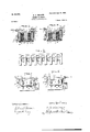
- FIG. 1 represents a plan view of a magnetic planer-chuck embodying my invention.
- Fig. 2 is a side elevation.
- Fig. 3 is a longitudinal sectional view online 3 3, Fig.1.
- Fig. 4 is a transverse sectional view of the shell, core, andwire coil on line 4 4, Fig. 1..
- Fig. 5 is a transverse sectional view of the shell, core, and wire coil on line 5 5, Fig. 1.
- Fig. 6 is a top view of the core removed from the shell.
- Fig. 7 is an end view showing the method of holding thin work supported upon one edge
- Fig. 8 is an end view showing the method of supporting thicker work.
- My present invention relates to that class of magnetic chucks which are adapted to be used on metal-planing machines for holding the work, and forms the subject of United States Letters Patent No. 564,296, granted to me July 21, 1896; and the objects of my present invention are to increase the magnetic power of the chuck upon one side of the central core, so that narrow or thin pieces of work which cover but a small part of the area of the face of the chuck will be more firmly held; also, to provide an increased magnetic attraction between the work and the edge of the rest or support attached to the side of the chuck, to provide improved means for supporting the work upon the chuck, and to prevent the short-circuiting of the electric cur rent due to the condensation of moisture within the chuck, and these objects are attained by the construction and arrangement of parts, as hereinafter described,and set forth in the annexed claims.
- A denotes a shell or case with a removable bottom A attached to the shell A by screws.
- the sides and ends of the shell A are solid, but the top is provided with a rectangular opening A, from one edge of which the-bars A project across and beyond the central core i B.
- the central core B is provided on its upper surface and integral therewith with transverse bars 13, adapted to enter the spaces between the bars A of the shell with their uppersurfaces flush with
- the ends of the bars B are united on one side by a bar or bridge B so that when the shell and core are placed together the bars B and bridge B will be inclosed within the opening in the top of the shell, with a narrow space C extending entirely around between the opposing edges of the shell and core and forming with the upper'surface of the shell A the face of the chuck upon which the work is supported.
- the core B is cutaway at B Fig. 6, between the bars B, so as to form air-spaces B", Fig. 5, between the core B and the bars A
- the narrow space 0 between the opposing edges of the core and shell is preferably filled with Babbitt metal or-other non-magnetic material, as shown at C in the sectional views.
- a magnetizing-coil of wire D having terminals connected with an electric supply by means of a socket D, cable D and switching mechanism D in the usual and well-known manner in chucks of this class. Connections are also made through the cable E with a socket E, adapted to receive an incandescent lamp for the purpose of indicat ing when the circuit through the coil is closed.
- The'electrical connections form no part of my present invention, and as they will be well understood by those conversant with electrical devices I have not shown nor described them in detail.
- a rest F Attached by bolts F, passing through slots F to one side of the shell A is a rest F, provided on opposite sides with the flanges or lips F and F As the side rest F forms part of the chuck and is magnetized by the coil D,
- a bracket I is attached to the opposite side-of the shell A and, capable of vertical adjustment, and supports the horizontal fingers I, which are capable of being adjustably attached to the bracket I, and are also capable of an endwise adjustment, by which they are brought against the side of the work to hold it in contact with the edge of the lip F so that in planing the upper surface of the work H the cutting-tool is prevented from pulling the work away from the lip F and withdrawingit from the field of magnetic attraction.
- a segmental piece J ofiron or steel
- a rocker which allows the upper edge of the work to rock slightly and be brought in to cont-act with theedge of the lip F
- Attached to the end of the shell A is a vertically-adjustable plate K, arranged to project above the face of the chuck and serve as a stop to prevent the endwise forward movement of the work as it is subjected to the action of the cutting-tool, and one of the lips of the side rest F is provided with a lug K projecting from its end and havinga shoulder K arranged to be brought into the plane of ,the bearing side of the end stop K andserve as a rest for the end of the work to hold it from tipping as it is being planed.
- the lips F and F are arranged to extend over a portion of the face of the chuck and preferably just over the longitudinal space 0 between the shellA and the baror bridge B so that the work when placed against the lip F will overlap the bar or bridge 13*, thereby spanning the longitudinal space 0 and formingamagnet-ic connection between the bridge B and the shell A through the lip F and strip G.
- the upper edge of the central core was provided with a sinuous or angular flange, which interlocked with corresponding an gular projections upon opposite sides of the opening in the upper face of the shell and.
- one of the objects of my invention is to causethe magnetic force of the chuck to be increased upon that side of the central core upon which the work is placed, and I accomplish this result by so constructing the interlocking members A and B of the chuck that the strips A, which are integral with the shell A on one side, shall extend beyond the core B, so that their free ends a shall project over the coil Don the side of the core and contiguous to the plane of the work-supporting edges of the lip F and strip G, and in uniting the ends of the strips 13 by a bar or bridge 13 so that the magnetic current between the core B and the side of the shell A, to which the side rest F is attached, will pass over the longitudinal space or gap 0, through the work and lip F and strip G, causing the work to be firmly held against the lip F and strip G and also against
- a magnetic chuck comprising a core, a magnetizing-coil and an inclosing shell, the combination of bars forming part of the shell on one side of the core and extending transversely across the core with their free ends projecting beyond the opposite side of the core, bars forming a part of said core alternating withthe bars of said shell and having their ends on one side of the core connected by a bar, or bridge, the bars of said core, and said shell beingseparated and forming a workholding face of opposite polarities, substantially as described.
- a magnetic chuck comprising a core, a magnetizing-coil and an inclosingshell, the combination of bars extending from one side of said shell transversely across said core, bars forming part of said core alternating with the bars of said shell and having their ends on one side of said core united by a bar, or bridge, and a side rest attached to said shell on the side next the bar, or bridge, and
- a shell A having bars A a core B having bars B alternating with the bars A, a bar, or bridge, B uniting the bars B on one side of the core, said bars B and A extending transversely across the core and being sepa-. rated to form a work-holding face of opposite polarities, substantially as described.
- a magnetic chuck the combination of a central core, a magnetizing-coil, an inclosing shell having openings to provide for a circulation of air within the shell and a series of insulating-strips inserted between the coil and the top and bottom of said shell with spaces between said strips, substantially as described.
- a magnetic chuck comprising a shell, a core and a magnetizing-coil, the combination with the shell of the chuck, of a side rest attached to said shell and vertically adjust-
Description
Patented lune l9, I900.
2 Sheets-Sheet I.
0. 8.. WALKER. MAGNETIC CHUCK.
(Application filed Feb. 28, 1899.)
C]- TEE-r E No. 65I,908.
(No Model.)
LIL-Erna sa as No. 65,908. Patented lime I9, 1900. 0. s. WALKER.
MAGNETIC CHUCK.
(Application filed Feb. 28, 1899.) i
(No Model.)
2 Sheets-Sheet 2.
U 5 WELLREK- parts in the different views.
UNITED STATES PATENT OFFICE;
OAKLEY S. WALKEl t, OF WORCESTER, MASSACHUSETTS.
Ml'AGNETIC CHUCK.
. SPECIFICATION forming part of Ltters Patent NO. 651,908, dated June 19, 1900. Application filed iEebruar/y 28, 1899- Serial No. 707,201. (No model.)
To an whont it may concern: j
Be it known that I, OAKLEY SL WALKER, a citizen of the United ,States, residing at Worcester, in the county of Worcester and Commonwealth of Massachusetts, have in vented anew and useful Improvement in Magnetic Chucks, of which the followingis aspecification, accompanied by drawings forming a part of the same, and in which- Figure 1 represents a plan view of a magnetic planer-chuck embodying my invention. Fig. 2 is a side elevation. Fig. 3 is a longitudinal sectional view online 3 3, Fig.1. Fig. 4 is a transverse sectional view of the shell, core, andwire coil on line 4 4, Fig. 1.. Fig. 5 is a transverse sectional view of the shell, core, and wire coil on line 5 5, Fig. 1. Fig. 6 is a top view of the core removed from the shell. Fig. 7 is an end view showing the method of holding thin work supported upon one edge, and Fig. 8 is an end view showing the method of supporting thicker work.
Similar reference-letters refer to similar My present invention relates to that class of magnetic chucks which are adapted to be used on metal-planing machines for holding the work, and forms the subject of United States Letters Patent No. 564,296, granted to me July 21, 1896; and the objects of my present invention are to increase the magnetic power of the chuck upon one side of the central core, so that narrow or thin pieces of work which cover but a small part of the area of the face of the chuck will be more firmly held; also, to provide an increased magnetic attraction between the work and the edge of the rest or support attached to the side of the chuck, to provide improved means for supporting the work upon the chuck, and to prevent the short-circuiting of the electric cur rent due to the condensation of moisture within the chuck, and these objects are attained by the construction and arrangement of parts, as hereinafter described,and set forth in the annexed claims.
Referring to the accompanying drawings, A denotes a shell or case with a removable bottom A attached to the shell A by screws.
B represents a central core held within the shell A and attached by screws to the removthe upper surfaces of the bars A.
able bottom A. The sides and ends of the shell A are solid, but the top is provided with a rectangular opening A, from one edge of which the-bars A project across and beyond the central core i B. The central core B is provided on its upper surface and integral therewith with transverse bars 13, adapted to enter the spaces between the bars A of the shell with their uppersurfaces flush with The ends of the bars B are united on one side by a bar or bridge B so that when the shell and core are placed together the bars B and bridge B will be inclosed within the opening in the top of the shell, with a narrow space C extending entirely around between the opposing edges of the shell and core and forming with the upper'surface of the shell A the face of the chuck upon which the work is supported. The core B is cutaway at B Fig. 6, between the bars B, so as to form air-spaces B", Fig. 5, between the core B and the bars A The narrow space 0 between the opposing edges of the core and shell is preferably filled with Babbitt metal or-other non-magnetic material, as shown at C in the sectional views.
Within the space between the core B and shell A is wound a magnetizing-coil of wire D, having terminals connected with an electric supply by means of a socket D, cable D and switching mechanism D in the usual and well-known manner in chucks of this class. Connections are also made through the cable E with a socket E, adapted to receive an incandescent lamp for the purpose of indicat ing when the circuit through the coil is closed. The'electrical connections form no part of my present invention, and as they will be well understood by those conversant with electrical devices I have not shown nor described them in detail.
Attached by bolts F, passing through slots F to one side of the shell A is a rest F, provided on opposite sides with the flanges or lips F and F As the side rest F forms part of the chuck and is magnetized by the coil D,
the greater the mass of metal in the lips the greater their magnetic attraction for the work bearing against them, and as it is frequently necessary to use a lip which is thinner than the work I make the lips F and F of different thicknesses, so that either can be used by reversing the rest.
by the construction Secured to the face of the chuck is a steel strip G, with one edge bearing against the side rest I and its opposite edge flush with the edge of the lip which projects over the face of the chuck, allowing a thin piece of work, similar to that shown at IT, Fig. '7, to beheld edgewise and in a vertical position upon the face of the chuck with its side bearing against the steel strip G and the lip F of the side rest, which *is capable of a vertical adjustment by means of the bolts F and slots W. A bracket I is attached to the opposite side-of the shell A and, capable of vertical adjustment, and supports the horizontal fingers I, which are capable of being adjustably attached to the bracket I, and are also capable of an endwise adjustment, by which they are brought against the side of the work to hold it in contact with the edge of the lip F so that in planing the upper surface of the work H the cutting-tool is prevented from pulling the work away from the lip F and withdrawingit from the field of magnetic attraction. I
When thicker pieces of work are to be planed, as shown at J, .Fig. 8, the fingers I are moved-back or removed and a segmental piece J, ofiron or steel, is placed beneath the work with its curved side resting upon the face of the chuck, thereby forming a rocker, which allows the upper edge of the work to rock slightly and be brought in to cont-act with theedge of the lip F Attached to the end of the shell A is a vertically-adjustable plate K, arranged to project above the face of the chuck and serve as a stop to prevent the endwise forward movement of the work as it is subjected to the action of the cutting-tool, and one of the lips of the side rest F is provided with a lug K projecting from its end and havinga shoulder K arranged to be brought into the plane of ,the bearing side of the end stop K andserve as a rest for the end of the work to hold it from tipping as it is being planed.
The lips F and F are arranged to extend over a portion of the face of the chuck and preferably just over the longitudinal space 0 between the shellA and the baror bridge B so that the work when placed against the lip F will overlap the bar or bridge 13*, thereby spanning the longitudinal space 0 and formingamagnet-ic connection between the bridge B and the shell A through the lip F and strip G.
In the magnetic chuck described in Letters Patent No.-564,296, granted to me July 21, 1896, the upper edge of the central core was provided with a sinuous or angular flange, which interlocked with corresponding an gular projections upon opposite sides of the opening in the upper face of the shell and.
therein shown the currents of magnetic force passed from the central core through walls upon each side of the shell in lines of equal resistance and a piece of work covering the faceof the chuck would be opposite provide a lateral rest for the side of the work,
such as that shown in the drawings, by the side rest F and its projecting lips, and the work in many cases does not extend beyond the central core B, its contact with the face of the chuck being confined entirely to one side of the central core, and one of the objects of my invention is to causethe magnetic force of the chuck to be increased upon that side of the central core upon which the work is placed, and I accomplish this result by so constructing the interlocking members A and B of the chuck that the strips A, which are integral with the shell A on one side, shall extend beyond the core B, so that their free ends a shall project over the coil Don the side of the core and contiguous to the plane of the work-supporting edges of the lip F and strip G, and in uniting the ends of the strips 13 by a bar or bridge 13 so that the magnetic current between the core B and the side of the shell A, to which the side rest F is attached, will pass over the longitudinal space or gap 0, through the work and lip F and strip G, causing the work to be firmly held against the lip F and strip G and also against the bar or bridge 13, and to the downward attraction of the bar 13*, I also add the magnetic attraction induced by the contact of the work with the bars, which are integral with the core and the ends aof the bars A A piece of work, therefore, like that shown at J and occupying the space on the face of the chuck at one side of its center, as'indicated by broken lines L, Fig. 1, will be subjected to the magnetic currents between the core B and. the shell on that side and also to a portion of the magnetic currents upon the opposite side of the core 13, due to the contact of the work with the bars A, which are integral with the opposite side of the shell. In the operation of the chuck the air becomes warmed. by the coilD, and its moisture is deposited upon the colder interior walls of the shell A, which, being subject to a continued electrical action, eventually causes a short circuit of the electric current, thereby rendering the chuck worthless. After much experiment I have discovered a remedy for this dilficulty, which consists in providing a series of holes M through the bottom plate A beneath the coil D and a series of holes through the side walls of the shell, as shown at M. These holes are usually covered with wire-gauze to prevent access'of dirt to the interior of the shell.
Beneath and above the coil -D, between it and the top and bottom of the shell, I insert narrow strips, preferably of wood N, placed bars B and A transversely across the coil-chamber, with spaces 0 between the strips to allow a free circulation of air across the coil D. The coil D is therefore held away from the uppar and lower walls'of the coil-chamber, and the free circulation of air tends to keep its temperature as low as that of the shell itself.
have shown the interlocking of uniform width and square ends I do not confine myself to the precise shape shown.
What I claim as my invention, to secure by Letters Patent, is-
1. In a magnetic chuck, comprising a core, a magnetizing-coil and an inclosing shell, the combination of bars forming part of the shell on one side of the core and extending transversely across the core with their free ends projecting beyond the opposite side of the core, bars forming a part of said core alternating withthe bars of said shell and having their ends on one side of the core connected by a bar, or bridge, the bars of said core, and said shell beingseparated and forming a workholding face of opposite polarities, substantially as described.
2. In a magnetic chuck, comprising a core, a magnetizing-coil and an inclosingshell, the combination of bars extending from one side of said shell transversely across said core, bars forming part of said core alternating with the bars of said shell and having their ends on one side of said core united by a bar, or bridge, and a side rest attached to said shell on the side next the bar, or bridge, and
. Although I and desire having a lip projecting over the face of thechuck, the bars of said core and said shell being separated and forming a work-holding face of opposite polarities, substantially as described.
3. In a magnetic chuck, the combination of a shell A, having bars A a core B having bars B alternating with the bars A, a bar, or bridge, B uniting the bars B on one side of the core, said bars B and A extending transversely across the core and being sepa-. rated to form a work-holding face of opposite polarities, substantially as described.
4. In a magnetic chuck, the combination of a shell, core and magnetizing-coil, of areversible side rest attached to said shell havmg lips of unequal thickness on opposite sides of said rest, substantially as described.
5. In a magnetic chuck, the combination with the body of the chuck, having a workholding face separated into two parts of opposite polarities, of a side rest attached to the body of the chuck and having a projecting lip provided with a shoulder to receive the end thrust of the work, substantially as described.
6. In a magnetic chuck, the combination with a side rest attached to one side of the chuck, of a bracket attached to the opposite side of the chuck and vertically adjustable thereon and fingers held by said vertically- 4 adjustable bracket, each of said fingers being longitudinally adjustable thereon, and arranged to hold the work in contact with said side rest, substantially as described.
7. In a magnetic chuck, the combination with a chuck-body, and a side rest attached to said chuck-body and having the same polarity, of a segmental support for the work, whereby the work is capable of a slight rocking motion to allow it to adjust itself to the side rest, substantially as described.
8. In a magnetic chuck, the combination of a central core, a magnetizing-coil, an inclosing shell having openings to provide for a circulation of air within the shell and a series of insulating-strips inserted between the coil and the top and bottom of said shell with spaces between said strips, substantially as described.
9. In a magnetic chuck, comprising a shell, a core and a magnetizing-coil, the combination with the shell of the chuck, of a side rest attached to said shell and vertically adjust-
Priority Applications (1)
| Application Number | Priority Date | Filing Date | Title |
|---|---|---|---|
| US70720199A US651908A (en) | 1899-02-28 | 1899-02-28 | Magnetic chuck. |
Applications Claiming Priority (1)
| Application Number | Priority Date | Filing Date | Title |
|---|---|---|---|
| US70720199A US651908A (en) | 1899-02-28 | 1899-02-28 | Magnetic chuck. |
Publications (1)
| Publication Number | Publication Date |
|---|---|
| US651908A true US651908A (en) | 1900-06-19 |
Family
ID=2720477
Family Applications (1)
| Application Number | Title | Priority Date | Filing Date |
|---|---|---|---|
| US70720199A Expired - Lifetime US651908A (en) | 1899-02-28 | 1899-02-28 | Magnetic chuck. |
Country Status (1)
| Country | Link |
|---|---|
| US (1) | US651908A (en) |
Cited By (6)
| Publication number | Priority date | Publication date | Assignee | Title |
|---|---|---|---|---|
| US2533348A (en) * | 1948-03-29 | 1950-12-12 | Edwin H Brandenburg | Permanent magnet chuck |
| US2561770A (en) * | 1948-06-29 | 1951-07-24 | Sundstrand Magnetic Products C | Magnetic chuck |
| US2752538A (en) * | 1951-09-22 | 1956-06-26 | Sundstrand Magnetic Products C | Magnetic work support |
| US4453704A (en) * | 1978-10-24 | 1984-06-12 | Wlajko Mihic | Apparatus for retaining blanks in working machines |
| US20040161115A1 (en) * | 2003-02-14 | 2004-08-19 | Loose Timothy C. | Gaming machine having improved audio control architecture |
| US20190176279A1 (en) * | 2017-12-11 | 2019-06-13 | Bystronic Laser Ag | Mounting device for machine tools and machine tool with a mounting device |
-
1899
- 1899-02-28 US US70720199A patent/US651908A/en not_active Expired - Lifetime
Cited By (7)
| Publication number | Priority date | Publication date | Assignee | Title |
|---|---|---|---|---|
| US2533348A (en) * | 1948-03-29 | 1950-12-12 | Edwin H Brandenburg | Permanent magnet chuck |
| US2561770A (en) * | 1948-06-29 | 1951-07-24 | Sundstrand Magnetic Products C | Magnetic chuck |
| US2752538A (en) * | 1951-09-22 | 1956-06-26 | Sundstrand Magnetic Products C | Magnetic work support |
| US4453704A (en) * | 1978-10-24 | 1984-06-12 | Wlajko Mihic | Apparatus for retaining blanks in working machines |
| US20040161115A1 (en) * | 2003-02-14 | 2004-08-19 | Loose Timothy C. | Gaming machine having improved audio control architecture |
| US20190176279A1 (en) * | 2017-12-11 | 2019-06-13 | Bystronic Laser Ag | Mounting device for machine tools and machine tool with a mounting device |
| US10625383B2 (en) * | 2017-12-11 | 2020-04-21 | Bystronic Laser Ag | Mounting device for machine tools and machine tool with a mounting device |
Similar Documents
| Publication | Publication Date | Title |
|---|---|---|
| US1301135A (en) | Fixture for use with magnetic chucks. | |
| US651908A (en) | Magnetic chuck. | |
| US1336928A (en) | Method and apparatus for alining work on v-blocks and the like for magnetic chucks | |
| US3017545A (en) | Device for magnetic clamping | |
| US687931A (en) | Magnetic holding-table for metal-working machines. | |
| US2268011A (en) | Permanent magnetic chuck | |
| US1222052A (en) | Magnetic chuck. | |
| US1232532A (en) | Magnetic chuck. | |
| US564296A (en) | Magnetic chuck | |
| US3179858A (en) | Controllable permanent magnetic chuck | |
| US1451268A (en) | Magnetic chuck | |
| US1125198A (en) | Magnetic chuck. | |
| US1484090A (en) | Rotary magnetic chuck | |
| US1415723A (en) | Bipolar magnetic chuck | |
| US1624076A (en) | Magnetic bar pole chuck | |
| US1435946A (en) | Magnetic chuck | |
| US1507006A (en) | Magnetic chuck | |
| US2533348A (en) | Permanent magnet chuck | |
| US1412776A (en) | Magnetic chuck | |
| US1254736A (en) | Magnetic chuck. | |
| US1079546A (en) | Magnetic chuck. | |
| US641012A (en) | Brush for dynamo-electric machines. | |
| US1517025A (en) | Island | |
| US2404072A (en) | Magnetic device | |
| US1433568A (en) | Aluminum body for magnetic chucks |