US6512940B1 - Subcutaneous spiral electrode for sensing electrical signals of the heart - Google Patents
Subcutaneous spiral electrode for sensing electrical signals of the heart Download PDFInfo
- Publication number
- US6512940B1 US6512940B1 US09/703,152 US70315200A US6512940B1 US 6512940 B1 US6512940 B1 US 6512940B1 US 70315200 A US70315200 A US 70315200A US 6512940 B1 US6512940 B1 US 6512940B1
- Authority
- US
- United States
- Prior art keywords
- electrode
- electrodes
- spiral
- recessed
- case
- Prior art date
- Legal status (The legal status is an assumption and is not a legal conclusion. Google has not performed a legal analysis and makes no representation as to the accuracy of the status listed.)
- Expired - Fee Related, expires
Links
Images


Classifications
-
- A—HUMAN NECESSITIES
- A61—MEDICAL OR VETERINARY SCIENCE; HYGIENE
- A61B—DIAGNOSIS; SURGERY; IDENTIFICATION
- A61B5/00—Measuring for diagnostic purposes; Identification of persons
- A61B5/68—Arrangements of detecting, measuring or recording means, e.g. sensors, in relation to patient
- A61B5/6846—Arrangements of detecting, measuring or recording means, e.g. sensors, in relation to patient specially adapted to be brought in contact with an internal body part, i.e. invasive
- A61B5/6847—Arrangements of detecting, measuring or recording means, e.g. sensors, in relation to patient specially adapted to be brought in contact with an internal body part, i.e. invasive mounted on an invasive device
- A61B5/6852—Catheters
-
- A—HUMAN NECESSITIES
- A61—MEDICAL OR VETERINARY SCIENCE; HYGIENE
- A61B—DIAGNOSIS; SURGERY; IDENTIFICATION
- A61B5/00—Measuring for diagnostic purposes; Identification of persons
- A61B5/0002—Remote monitoring of patients using telemetry, e.g. transmission of vital signals via a communication network
- A61B5/0031—Implanted circuitry
-
- A—HUMAN NECESSITIES
- A61—MEDICAL OR VETERINARY SCIENCE; HYGIENE
- A61B—DIAGNOSIS; SURGERY; IDENTIFICATION
- A61B5/00—Measuring for diagnostic purposes; Identification of persons
- A61B5/24—Detecting, measuring or recording bioelectric or biomagnetic signals of the body or parts thereof
- A61B5/25—Bioelectric electrodes therefor
- A61B5/279—Bioelectric electrodes therefor specially adapted for particular uses
- A61B5/28—Bioelectric electrodes therefor specially adapted for particular uses for electrocardiography [ECG]
- A61B5/283—Invasive
- A61B5/287—Holders for multiple electrodes, e.g. electrode catheters for electrophysiological study [EPS]
-
- A—HUMAN NECESSITIES
- A61—MEDICAL OR VETERINARY SCIENCE; HYGIENE
- A61N—ELECTROTHERAPY; MAGNETOTHERAPY; RADIATION THERAPY; ULTRASOUND THERAPY
- A61N1/00—Electrotherapy; Circuits therefor
- A61N1/02—Details
- A61N1/04—Electrodes
- A61N1/05—Electrodes for implantation or insertion into the body, e.g. heart electrode
-
- A—HUMAN NECESSITIES
- A61—MEDICAL OR VETERINARY SCIENCE; HYGIENE
- A61B—DIAGNOSIS; SURGERY; IDENTIFICATION
- A61B2562/00—Details of sensors; Constructional details of sensor housings or probes; Accessories for sensors
- A61B2562/04—Arrangements of multiple sensors of the same type
- A61B2562/043—Arrangements of multiple sensors of the same type in a linear array
-
- A—HUMAN NECESSITIES
- A61—MEDICAL OR VETERINARY SCIENCE; HYGIENE
- A61B—DIAGNOSIS; SURGERY; IDENTIFICATION
- A61B5/00—Measuring for diagnostic purposes; Identification of persons
- A61B5/72—Signal processing specially adapted for physiological signals or for diagnostic purposes
- A61B5/7203—Signal processing specially adapted for physiological signals or for diagnostic purposes for noise prevention, reduction or removal
- A61B5/7207—Signal processing specially adapted for physiological signals or for diagnostic purposes for noise prevention, reduction or removal of noise induced by motion artifacts
Definitions
- the present invention relates generally to implantable pacemakers and more particularly to a subcutaneous electrode used to sense, record, and acquire electrocardiographic data and waveform tracings from an implanted pacemaker without the need for or use of surface (skin) electrodes. More particularly, the present invention relates to spiral electrodes placed into recesses incorporated within a compliant, insulative “surround.” Each spiral electrode becomes an integral element of a Subcutaneous Electrode Array or SEA that, in turn, detects cardiac depolarizations communicable and displayable by a portable device programmer.
- SEA Subcutaneous Electrode Array
- ECG electrocardiogram
- an ECG recording device is commonly attached to the patient via ECG leads connected to pads arrayed on the patient's body so as to achieve a recording that displays the cardiac waveforms in any one of 12 possible vectors.
- Such systems employ detection of the occurrence of the P-wave and R-wave, analysis of the rate, regularity, and onset of variations in the rate of recurrence of the P-wave and R-wave, the morphology of the P-wave and R-wave and the direction of propagation of the depolarization represented by the P-wave and R-wave in the heart.
- the detection, analysis and storage of such EGM data within implanted medical devices are well known in the art.
- Acquisition and use of ECG tracing(s) has generally been limited to the use of an external ECG recording machine attached to the patient via surface electrodes of one sort or another.
- the aforementioned ECG systems that utilize detection and analysis of the PQRST complex are all dependent upon the spatial orientation and number of electrodes available near or around the heart to pick up the depolarization wave front.
- implantable medical device systems As the functional sophistication and complexity of implantable medical device systems increased over the years, it has become increasingly more important for such systems to include a system for facilitating communication between one implanted device and another implanted device and/or an external device, for example, a programming console, monitoring system, or the like.
- an external device for example, a programming console, monitoring system, or the like.
- the implanted device For diagnostic purposes, it is desirable that the implanted device be able to communicate information regarding the device's operational status and the patient's condition to the physician or clinician.
- State of the art implantable devices are available which can even transmit a digitized electrical signal to display electrical cardiac activity (e.g., an ECG, EGM, or the like) for storage and/or analysis by an external device.
- ECG electrical cardiac activity
- EGM electrical cardiac activity
- the cardiologist has several tools from which to choose.
- Such tools include twelve-lead electrocardiograms, exercise stress electrocardiograms, Holter monitoring, radioisotope imaging, coronary angiography, myocardial biopsy, and blood serum enzyme tests.
- the twelve-lead electrocardiogram is generally the first procedure used to determine cardiac status prior to implanting a pacing system; thereafter, the physician will normally use an ECG available through the programmer to check the pacemaker's efficacy after implantation.
- ECG tracings are placed into the patient's records and used for comparison to more recent tracings. It must be noted, however, that whenever an ECG recording is required (whether through a direct connection to an ECG recording device or to a pacemaker programmer), external electrodes and leads must be used.
- Electrodes attached externally to the body are a major source of signal quality problems and analysis errors because of susceptibility to interference such as muscle noise, power line interference, high frequency communication equipment interference, and baseline shift from respiration. Signal degradation also occurs due to contact problems, ECG waveform artifacts, and patient discomfort. Externally attached electrodes are subject to motion artifacts from positional changes and the relative displacement between the skin and the electrodes. Furthermore, external electrodes require special skin preparation to ensure adequate electrical contact. Such preparation, along with positioning the electrode and attachment of the ECG lead to the electrode needlessly prolongs the pacemaker follow-up session.
- One possible approach is to equip the implanted pacemaker with the ability to detect cardiac signals and transform them into a tracing that is the same as or comparable to tracings obtainable via ECG leads attached to surface electrodes.
- U.S. Pat. No. 5,331,966 to Bennett discloses a method and apparatus for providing an enhanced capability of detecting and gathering electrical cardiac signals via an array of relatively closely spaced subcutaneous electrodes (located on the body of an implanted device).
- the present invention encompasses a Subcutaneous Electrode Spiral, Spiral Electrode, as a preferred embodiment, that is embedded individually into three or four recessed casings placed in a compliant surround that is attached to the perimeter of an implanted pacemaker. These electrodes are electrically connected to the circuitry of the implanted pacemaker and detect cardiac depolarization waveforms displayable as electrocardiographic tracings on the pacemaker Programmer screen when the programming head is positioned above an implanted pacemaker (or other implanted device) so equipped with a leadless Subcutaneous Electrode Array (SEA).
- SEA Leadless Subcutaneous Electrode Array
- the recessed casing is composed of a polymer.
- This casing has walls into which body fluid is allowed to flow so that the body fluid is above and around the spiral, spiral coil, which is maintained within the casing by a small circumferential well constructed into the base of the recessed casing.
- the spiral coil may be constructed from any of the titanium group of metals, as well as platinum, platinum alloys, or any of the platinum group of metals with or without alloying components.
- This spiral coil constitutes the proximal end of a continuous wire that, upon egress from the recessed casing, is insulated by tubular, insulative material such as silicone.
- the insulated tubular wiring fits into channel(s) located on the inner arc of the aforementioned compliant surround.
- the distal end of this wire is welded to a connector feedthrough assembly in contact with amplifier(s) in the microprocessor circuitry.
- the present invention is designed to solve several problems that may be encountered in the use of subcutaneous electrodes generally.
- the electrical potentials from the cardiac depolarizations are very small, in the order of tens of microvolts. As a result, the signal that reaches the electrodes may have a low slew rate.
- Solid, plate electrodes exhibit noise spikes and potential drifts that are large in comparison to the cardiac signals. These plate electrodes themselves may be the major contributors to such noise. Contamination of electrode surfaces at the molecular level may cause extraneous voltage excursions large enough to interfere with the sensing function. Motion artifacts from the perturbation caused by fluid or tissue motion next to the surface has been demonstrated in tank tests, and represents a commonly observed phenomenon.
- the present invention in its preferred embodiment, solves these issues in that it is a spiral, subcutaneous electrode that can be attached to a pulse generator via a compliant surround and provide a reliable response.
- the electrode has a large surface area, is manufactured from low cost materials, and can be assembled in an inexpensive way.
- the surface of the electrode has no direct contact with body tissue and moving body fluids, but it is treated with electrode coatings such as platinum black or titanium nitride to enhance its signal-conducting and depolarization properties.
- electrode coatings such as platinum black or titanium nitride to enhance its signal-conducting and depolarization properties.
- Such enhancing coatings are important since, as time passes, the pacemaker and, with it, the electrodes become encapsulated in scar tissue and thus come into indirect contact with the body tissue. Even indirect tissue contact may have a damping effect on the detection ability of the electrode if not treated with enhancing coatings.
- the electrode affords a continuous wire connection, without weld or bonds on the electrode surface. Moreover, the electrode is anchored in the device free of any chemical bonding that might cause potential excursions due to electro active species being released to the electrode surface. The portion of the electrode covered by the recessed casing is minimal thereby preventing any potential excursions caused by fluid creep or by trapped oxygen or hydrogen gradients, or P h gradients.
- a second embodiment of the present invention employs a coiled electrode design that is manufactured in a rectangular configuration. This electrode has all the same electrical and signal detection properties as the spiral electrode and is constructed of the same materials and has the same enhancing coatings.
- a third embodiment of the present invention uses a flat plated electrode embedded within the well of the recessed casing.
- the bottom of the recess or well is patterned with a cross hatch of elevations and depressions with a minimum of contact area between the plate and the polymer used in the recessed casing.
- the purpose of the cross-hatch is to support the electrode and provide fluid contact to the underside of the electrode interface.
- a protective cap vented to allow fluid ingress to the active electrode element, may be placed over the well containing the flat electrode. This cap applies pressure on the electrode, pressing it against the textured bottom of the recess or well, thus preventing motion of the electrode. This cap also serves to dampen any external fluid motion that might otherwise reach the electrode and cause electro kinetic potential transients.
- the electrodes' surfaces require protection during handling as well as to prevent contamination.
- a coating such as may be provided by Dexamethazone Sodium Phosphate, provides such protection as well as enhancing the wetting of the electrode surface after implant.
- Conductive hydro gels applied wet and allowed to dry, may also be applied to the electrode surfaces to protect them from damage during handling and prevent contamination.
- the spacing of the electrodes in the present invention around the compliant surround provides maximal electrode spacing and, at the same time, appropriate insulation from the pacemaker casing due to the insulative properties of the surround and the cup recesses into which the electrodes are placed.
- the positioning maintains a maximum and equal distance between the electrode pairs.
- Such spacing with the four-electrode embodiment maintains the maximum average signal due to the fact that the spacing of the two vectors is equal and the angle between these vectors is 90°, as is shown in mathematical modeling.
- Such orthogonal spacing of the electrode pairs also minimizes signal variation.
- An alternate three-electrode embodiment has the electrodes arranged within the shroud in an equilateral triangle along the perimeter of the implanted pacemaker. Vectors in this embodiment can be combined to provide adequate sensing of cardiac signals (ECGs).
- the present invention allows the physician or medical technician to perform leadless follow-up that, in turn, eliminates the time it takes to attach external leads to the patient. Such timesavings can reduce the cost of follow-up, as well as making it possible for the physician or medical technician to see more patients during each day.
- other uses include: Holter monitoring with event storage, arrhythmia detection and monitoring, capture detection, ischemia detection and monitoring (S-T elevation and suppression on the ECG), changes in QT interval, and transtelephonic monitoring.
- FIG. 1 is an illustration of a body-implantable device system in accordance with the present invention, including a hermetically sealed device implanted in a patient and an external programming unit.
- FIG. 2 is a perspective view of the external programming unit of FIG. 1 .
- FIG. 3 is a block diagram of the implanted device from FIG. 1 .
- FIG. 4 is a sectional view of surround shroud displaying electrical connections of the electrodes to the hybrid circuitry.
- FIG. 5 is a cross sectional view of a spiral coil, which is one embodiment of an electrode practiced in the present invention.
- FIG. 6 is a cross sectional view of spiral coil housed in a well at the base of a recessed casing.
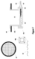
- FIG. 7 is a cross sectional view of a recessed cup that employs a cross hatch of elevations and depressions in the well at the base of the cup.
- FIG. 8 is a cross sectional view of a vented protective cap fitting over and into the recessed cup.
- FIG. 9 is a cross sectional view of a rectangular coil electrode according to an alternate embodiment of the present invention.
- FIG. 1 is an illustration of an implantable medical device system adapted for use in accordance with the present invention.
- the medical device system shown in FIG. 1 includes an implantable device 10 —a pacemaker in this embodiment—which has been implanted in a patient 12 .
- pacemaker 10 is housed within a hermetically sealed, biologically inert outer casing, which may itself be conductive so as to serve as an indifferent electrode in the pacemaker's pacing/sensing circuit.
- One or more pacemaker leads, collectively identified with reference numeral 14 in FIG. 1 are electrically coupled to pacemaker 10 in a conventional manner and extend into the patient's heart 16 via a vein 18 .
- leads 14 Disposed generally near the distal end of leads 14 are one or more exposed conductive electrodes for receiving electrical cardiac signals and/or for delivering electrical pacing stimuli to heart 16 .
- leads 14 may be implanted with its distal end situated in the atrium and/or ventricle of heart 16 .
- an external programming unit 20 for non-invasive communication with implanted device 10 via uplink and downlink communication channels, to be hereinafter described in further detail.
- a programming head 22 Associated with programming unit 20 is a programming head 22 , in accordance with conventional medical device programming systems, for facilitating two-way communication between implanted device 10 and programmer 20 .
- a programming head such as that depicted in FIG.
- the implant site of the device usually within 2- to 3-inches of skin contact
- one or more antennae within the head can send RF signals to, and receive RF signals from, an antenna disposed within the hermetic enclosure of the implanted device or disposed within the connector block of the device, in accordance with common practice in the art.
- FIG. 2 there is shown a perspective view of programming unit 20 in accordance with the presently disclosed invention.
- programmer 20 includes a processing unit (not shown in the Figures) that in accordance with the presently disclosed invention is a personal computer type motherboard, e.g., a computer motherboard including an Intel Pentium 3 microprocessor and related circuitry such as digital memory.
- a personal computer type motherboard e.g., a computer motherboard including an Intel Pentium 3 microprocessor and related circuitry such as digital memory.
- programmer 20 comprises an outer housing 60 , which is preferably made of thermal plastic or another suitably rugged yet relatively light-weight material.
- a carrying handle, designated generally as 62 in FIG. 2 is integrally formed into the front of housing 60 . With handle 62 , programmer 20 can be carried like a briefcase.
- Display screen 64 is disposed on the upper surface of housing 60 .
- Display screen 64 folds down into a closed position (not shown) when programmer 20 is not in use, thereby reducing the size of programmer 20 and protecting the display surface of display 64 during transportation and storage thereof.
- a floppy disk drive is disposed within housing 60 and is accessible via a disk insertion slot (not shown).
- a hard disk drive is also disposed within housing 60 , and it is contemplated that a hard disk drive activity indicator, (e.g., an LED, not shown) could be provided to give a visible indication of hard disk activation.
- programmer 20 is equipped with an internal printer (not shown) so that a hard copy of a patient's ECG or of graphics displayed on the programmer's display screen 64 can be generated.
- printers such as the AR-100 printer available from General Scanning Co., are known and commercially available.
- Articulating display screen 64 is preferably of the LCD or electro-luminescent type, characterized by being relatively thin as compared, for example, a cathode ray tube (CRT) or the like.
- display screen 64 is operatively coupled to the computer circuitry disposed within housing 60 and is adapted to provide a visual display of graphics and/or data under control of the internal computer.
- FIG. 3 is a block diagram of the electronic circuitry that makes up pulse generator 10 in accordance with the presently disclosed invention.
- pacemaker 10 comprises a primary stimulation control circuit 20 for controlling the device's pacing and sensing functions.
- the circuitry associated with stimulation control circuit 20 may be of conventional design, in accordance, for example, with what is disclosed Pat. No. 5,052,388 issued to Sivula et al., “Method and apparatus for implementing activity sensing in a pulse generator.”
- Pat. No. 5,052,388 issued to Sivula et al.
- stimulation control circuit 20 in FIG. 3 includes sense amplifier circuitry 24 , stimulating pulse output circuitry 26 , a crystal clock 28 , a random-access memory and read-only memory (RAM/ROM) unit 30 , and a central processing unit (CPU) 32 , all of which are well-known in the art.
- sense amplifier circuitry 24 stimulating pulse output circuitry 26 , a crystal clock 28 , a random-access memory and read-only memory (RAM/ROM) unit 30 , and a central processing unit (CPU) 32 , all of which are well-known in the art.
- CPU central processing unit
- Pacemaker 10 also includes internal communication circuit 34 so that it is capable communicating with external programmer/control unit 20 , as described in FIG. 2 in greater detail.
- pulse generator 10 is coupled to one or more leads 14 which, when implanted, extend transvenously between the implant site of pulse generator 10 and the patient's heart 16 , as previously noted with reference to FIG. 1 .
- leads 14 which, when implanted, extend transvenously between the implant site of pulse generator 10 and the patient's heart 16 , as previously noted with reference to FIG. 1 .
- the connections between leads 14 and the various internal components of pulse generator 10 are facilitated by means of a conventional connector block assembly 11 , shown in FIG. 1 .
- the coupling of the conductors of leads and internal electrical components of pulse generator 10 may be facilitated by means of a lead interface circuit 19 which functions, in a multiplexer-like manner, to selectively and dynamically establish necessary connections between various conductors in leads 14 , including, for example, atrial tip and ring electrode conductors ATIP and ARING and ventricular tip and ring electrode conductors VTIP and VRING, and individual electrical components of pulse generator 10 , as would be familiar to those of ordinary skill in the art.
- the specific connections between leads 14 and the various components of pulse generator 10 are not shown in FIG.
- leads 14 will necessarily be coupled, either directly or indirectly, to sense amplifier circuitry 24 and stimulating pulse output circuit 26 , in accordance with common practice, such that cardiac electrical signals may be conveyed to sensing circuitry 24 , and such that stimulating pulses may be delivered to cardiac tissue, via leads 14 .
- the protection circuitry commonly included in implanted devices to protect, for example, the sensing circuitry of the device from high voltage stimulating pulses.
- stimulation control circuit 20 includes central processing unit 32 which may be an off-the-shelf programmable microprocessor or micro controller, but in the present invention is a custom integrated circuit. Although specific connections between CPU 32 and other components of stimulation control circuit 20 are not shown in FIG. 3, it will be apparent to those of ordinary skill in the art that CPU 32 functions to control the timed operation of stimulating pulse output circuit 26 and sense amplifier circuit 24 under control of programming stored in RAM/ROM unit 30 . It is believed that those of ordinary skill in the art will be familiar with such an operative arrangement.
- crystal oscillator circuit 28 in the presently preferred embodiment a 32,768-Hz crystal controlled oscillator, provides main timing clock signals to stimulation control circuit 20 .
- the lines over which such clocking signals are provided to the various timed components of pulse generator 10 are omitted from FIG. 3 for the sake of clarity.
- pulse generator 10 depicted in FIG. 3 are powered by means of a battery (not shown) which is contained within the hermetic enclosure of pacemaker 10 , in accordance with common practice in the art. For the sake of clarity in the Figures, the battery and the connections between it and the other components of pulse generator 10 are not shown.
- Stimulating pulse output circuit 26 which functions to generate cardiac stimuli under control of signals issued by CPU 32 , may be, for example, of the type disclosed in U.S. Pat. No. 4,476,868 to Thompson, entitled “Body Stimulator Output Circuit,” which patent is hereby incorporated by reference herein in its entirety. Again, however, it is believed that those of ordinary skill in the art could select from among many various types of prior art pacing output circuits that would be suitable for the purposes of practicing the present invention.
- Sense amplifier circuit 24 which is of conventional design, functions to receive electrical cardiac signals from leads 14 and to process such signals to derive event signals reflecting the occurrence of specific cardiac electrical events, including atrial contractions (P-waves) and ventricular contractions (R-waves).
- CPU provides these event-indicating signals to CPU 32 for use in controlling the synchronous stimulating operations of pulse generator 10 in accordance with common practice in the art.
- these event-indicating signals may be communicated, via uplink transmission, to external programming unit 20 for visual display to a physician or clinician.
- pacemaker 10 may include numerous other components and subsystems, for example, activity sensors and associated circuitry. The presence or absence of such additional components in pacemaker 10 , however, is not believed to be pertinent to the present invention, which relates primarily to the implementation and operation of communication subsystem 34 in pacemaker 10 , and an associated communication subsystem in external unit 20 .
- FIG. 4 is a sectional view of surround shroud 48 displaying electrical connections of the electrodes to the hybrid circuitry surrounded by insulators 43 .
- Surround displays recessed cups 49 b and electrical contacts 49 a all of which are connected to the hybrid circuitry (not shown) via tubular wiring 53 .
- Tubular wiring 53 is welded to feedthrough contacts 52 located on upper portion of the board holding the hybrid circuitry.
- Other contacts 64 electrically connect the atrial and ventricular pacing lead tip and ring to the hybrid circuitry.
- FIG. 5 is a cross sectional view of spiral coil 61 , which is the preferred embodiment of an electrode practiced in the present invention.
- Spiral coil 61 consists of a wire of titanium or any of the titanium group of metals, platinum, platinum alloy, or any platinum group of metals whose surface may be treated by sputtering, platinization, ion milling, sintering, etching, or a combination of these processes to create a large specific surface area.
- Spiral coil 61 a is designed to fit into recessed well 49 c (see FIG. 6 ), within which spiral coil 61 b rests.
- the protruding end of spiral coil 61 c is manufactured continuous with tubular wiring 53 (see FIG. 6 ).
- the one-piece continuous design eliminates an additional weld or connection at the actual electrode.
- the elimination of the weld in this area is significant, because it eradicates the possibility of two dissimilar metals interacting within the ionic environment and adding an erroneous signal to the system. Removing the weld also eliminates any intermetalics formed during the weld.
- FIG. 6 is a cross sectional view of spiral coil 61 fitted into well 49 c at the base of recessed cup 49 b that is fitted into compliant shroud 48 (see FIG. 4 ).
- Thin film coatings via sputtering (porous TiN), platinization (platinum black), or applications of RuO, ion milling, sintering, etching, or a combination of these processes to create a large specific surface area may be used to treat the surface of spiral coil wire 61 . Larger surface areas decrease the interfacial impedance, thereby allowing lower impedances at lower frequencies, thereby increase the signal-to-noise ratio.
- Wire is manufactured of any of the titanium group of metals, as well as platinum, platinum alloy, or any of the platinum group of metals, with or without alloying components.
- the spaces around spiral coil 61 allow body fluid to flow around, between, and below the metal coils.
- Body fluids have conductive properties that allow cardiac depolarization waves to reach spiral electrode 61 .
- the depolarization waves are detected as changes in electrical potential and transmitted via continuous tubular wire protected by insulator 63 as wire exits well 49 c .
- Tubular material 53 keeps the wire insulated from other electrical potentials and protects the continuous wire.
- This continuous, conductive wire carries the signal(s) to the amplifier(s), hybrid circuitry, and microprocessor for processing and conversion into ECG tracings that may be printed by the printer located in programmer 20 (see FIG. 2 ).
- Compliant shroud 48 (see FIG. 4) serves to maintain the recessed cup in position relative to other coils which spacing is required for orthogonal or equilateral detection of the cardiac depolarization waves.
- FIG. 7 is a cross sectional view of a recessed cup that employs a crosshatch of elevations and depressions 66 in well 49 c at base of recessed cup 49 b . These elevations and depressions are continuous with the polymer used in the recessed up and well.
- elevations and depressions 66 mechanically stabilize the electrode and reduce the possibility of electro kinetic potential disturbances on the electrode (tissue or fluid motion artifact).
- the pattern of crosshatched elevations and depressions provide a minimum contact area between the wire and the polymer used to form the recessed cup 49 b and well 49 c .
- the purpose of the crosshatch is to support electrode 68 while providing fluid contact around, between, and below underside of electrode.
- Body fluids have conductive properties that allow cardiac depolarization waves to reach electrode 68 . Since thin, solid, spherical electrode 68 is not continuous with tubular wiring 53 , small metal plate 65 bonded or welded to tubular wiring 53 is welded to underside of electrode 68 .
- Cardiac depolarization waves are detected as changes in electrical potential and transmitted via continuous tubular wire protected by insulator 63 as wire exits well 49 c .
- a tubular material 53 that keeps the wire insulated from other electrical potentials then protects the continuous wire.
- This conductive wire carries the signal(s) to the amplifier(s), hybrid circuitry, and microprocessor for processing and conversion into ECG tracings that are printed by the printer located in programmer 20 (FIG. 2 ).
- Compliant shroud 48 (see FIG. 4) serves to maintain the recessed cup in position relative to other coils which spacing is required for orthogonal or equilateral detection of the cardiac depolarization waves.
- FIG. 8 is a cross sectional view of vented protective cap 69 a fitted over and into recessed cup 49 b .
- Protective cap 69 a is vented to allow fluid ingress to the active electrode element and is placed over the well 69 c containing active electrode 68 .
- This cap slides into recessed cup 49 b , contacts electrode 68 and applies pressure 70 on the electrode, pressing it against the crosshatched bottom 66 of well 49 c , thus preventing motion of the electrode.
- the cap constructed of a polymer such as urethane, also serves to dampen any external fluid motion that might otherwise reach the active element and cause electro kinetic potential transients.
- a preferred design for the openings in the cap is one in which the support elements all run perpendicular to the elements of the coiled wire, i.e., radially as shown in the drawing 69 a.
- the ribs in cross section 69 b are rounded on top to eliminate sharp edges, presenting a smooth appearance.
- the outer diameter of the protective cap is sized to provide a sliding fit 69 c into the well containing the electrode.
- the protective cap may then be bonded to the wall of the recessed casing 49 b with a suitable bonding agent.
- the cap and the electrode well must accommodate the wire 53 leading to the hybrid circuitry.
- a small opening in the side of the recessed casing serves to carry tubular wire from electrode to hybrid circuitry.
- Insulator 63 serves as anchor for wire 53 while the bonding material to small metal plate 65 serves as a seal.
- FIG. 9 shows a cross sectional view of rectangular coil electrode 70 and 71 , as well as a perspective view 72 of the same electrode which is an alternative embodiment of the present invention.
- Rectangular coil 70 consists of a wire of titanium or any of the titanium group of metals, platinum, platinum alloy, or any platinum group of metals whose surface may be treated by sputtering, platinization, ion milling, sintering, etching, or a combination of these processes to create a large specific surface area.
- Rectangular coil 70 is designed to fit into a rectangular recessed well 49 c (modified from that shown in FIG. 6 ), within which rectangular coil 71 rests.
- the protruding end of rectangular coil 70 a is manufactured continuous with tubular wiring 53 (see FIG. 6 ).
- the one-piece continuous design eliminates an additional weld or connection at the actual electrode.
- the elimination of the weld in this area is significant, because it eradicates the possibility of two dissimilar metals interacting within the ionic environment and adding an erroneous signal to the system. Removing the weld also eliminates any intermetalics formed during the weld.
Landscapes
- Health & Medical Sciences (AREA)
- Life Sciences & Earth Sciences (AREA)
- Engineering & Computer Science (AREA)
- Heart & Thoracic Surgery (AREA)
- Veterinary Medicine (AREA)
- Public Health (AREA)
- General Health & Medical Sciences (AREA)
- Animal Behavior & Ethology (AREA)
- Biomedical Technology (AREA)
- Biophysics (AREA)
- Medical Informatics (AREA)
- Molecular Biology (AREA)
- Surgery (AREA)
- Pathology (AREA)
- Physics & Mathematics (AREA)
- Cardiology (AREA)
- Physiology (AREA)
- Computer Networks & Wireless Communication (AREA)
- Nuclear Medicine, Radiotherapy & Molecular Imaging (AREA)
- Radiology & Medical Imaging (AREA)
- Electrotherapy Devices (AREA)
Abstract
An implantable pacemaker is provided with subcutaneous spiral electrodes for sensing electrical signals of the heart. Subcutaneous spirals or spiral electrodes are embedded individually into three or four recessed casings placed in a compliant surround that is attached to the perimeter of the implanted medical device. The electrodes are electrically connected to the circuitry of the implanted pacemaker and detect cardiac depolarization waveforms displayable as electrocardiographic tracings on an external instrument such as a programmer. The spiral electrode constitutes the proximal end of a continuous wire that upon egress from the recessed casing is insulated using insulative material.
Description
The present invention relates generally to implantable pacemakers and more particularly to a subcutaneous electrode used to sense, record, and acquire electrocardiographic data and waveform tracings from an implanted pacemaker without the need for or use of surface (skin) electrodes. More particularly, the present invention relates to spiral electrodes placed into recesses incorporated within a compliant, insulative “surround.” Each spiral electrode becomes an integral element of a Subcutaneous Electrode Array or SEA that, in turn, detects cardiac depolarizations communicable and displayable by a portable device programmer.
The electrocardiogram (ECG) is commonly used in medicine to determine the status of the electrical conduction system of the human heart. As practiced, an ECG recording device is commonly attached to the patient via ECG leads connected to pads arrayed on the patient's body so as to achieve a recording that displays the cardiac waveforms in any one of 12 possible vectors.
Since the implantation of the first cardiac pacemaker, implantable medical device technology has advanced with the development of sophisticated, programmable cardiac pacemakers, pacemaker-cardioverter-defibrillator arrhythmia control devices and drug administration devices designed to detect arrhythmias and apply appropriate therapies. The detection and discrimination between various arrhythmic episodes in order to trigger the delivery of an appropriate therapy is of considerable interest. Prescription for implantation and programming of the implanted device are based on the analysis of the PQRST electrocardiogram (ECG) and the electrogram (EGM). The waveforms are usually separated for such analysis into the P-wave and R-wave in systems that are designed to detect the depolarization of the atrium and ventricle respectively. Such systems employ detection of the occurrence of the P-wave and R-wave, analysis of the rate, regularity, and onset of variations in the rate of recurrence of the P-wave and R-wave, the morphology of the P-wave and R-wave and the direction of propagation of the depolarization represented by the P-wave and R-wave in the heart. The detection, analysis and storage of such EGM data within implanted medical devices are well known in the art. Acquisition and use of ECG tracing(s), on the other hand, has generally been limited to the use of an external ECG recording machine attached to the patient via surface electrodes of one sort or another.
The aforementioned ECG systems that utilize detection and analysis of the PQRST complex are all dependent upon the spatial orientation and number of electrodes available near or around the heart to pick up the depolarization wave front.
As the functional sophistication and complexity of implantable medical device systems increased over the years, it has become increasingly more important for such systems to include a system for facilitating communication between one implanted device and another implanted device and/or an external device, for example, a programming console, monitoring system, or the like. For diagnostic purposes, it is desirable that the implanted device be able to communicate information regarding the device's operational status and the patient's condition to the physician or clinician. State of the art implantable devices are available which can even transmit a digitized electrical signal to display electrical cardiac activity (e.g., an ECG, EGM, or the like) for storage and/or analysis by an external device. The surface ECG, however, has remained the standard diagnostic tool since the very beginning of pacing and remains so today.
To diagnose and measure cardiac events, the cardiologist has several tools from which to choose. Such tools include twelve-lead electrocardiograms, exercise stress electrocardiograms, Holter monitoring, radioisotope imaging, coronary angiography, myocardial biopsy, and blood serum enzyme tests. Of these, the twelve-lead electrocardiogram (ECG) is generally the first procedure used to determine cardiac status prior to implanting a pacing system; thereafter, the physician will normally use an ECG available through the programmer to check the pacemaker's efficacy after implantation. Such ECG tracings are placed into the patient's records and used for comparison to more recent tracings. It must be noted, however, that whenever an ECG recording is required (whether through a direct connection to an ECG recording device or to a pacemaker programmer), external electrodes and leads must be used.
Unfortunately, surface electrodes have some serious drawbacks. For example, electrocardiogram analysis performed using existing external or body surface ECG systems can be limited by mechanical problems and poor signal quality. Electrodes attached externally to the body are a major source of signal quality problems and analysis errors because of susceptibility to interference such as muscle noise, power line interference, high frequency communication equipment interference, and baseline shift from respiration. Signal degradation also occurs due to contact problems, ECG waveform artifacts, and patient discomfort. Externally attached electrodes are subject to motion artifacts from positional changes and the relative displacement between the skin and the electrodes. Furthermore, external electrodes require special skin preparation to ensure adequate electrical contact. Such preparation, along with positioning the electrode and attachment of the ECG lead to the electrode needlessly prolongs the pacemaker follow-up session. One possible approach is to equip the implanted pacemaker with the ability to detect cardiac signals and transform them into a tracing that is the same as or comparable to tracings obtainable via ECG leads attached to surface electrodes.
It is known in the art to monitor electrical activity of the human heart for diagnostic and related medical purposes. U.S. Pat. No. 4,023,565 issued to Ohlsson describes circuitry for recording ECG signals from multiple lead inputs. Similarly, U.S. Pat. No. 4,263,919 issued to Levin, U.S. Pat. No. 4,170,227 issued to Feldman, et al, and U.S. Pat. No. 4,593,702 issued to Kepski, et al, describe multiple electrode systems that combine surface EKG signals for artifact rejection.
The primary use for multiple electrode systems in the prior art appears to be vector cardiography from ECG signals taken from multiple chest and limb electrodes. This is a technique whereby the direction of depolarization of the heart is monitored, as well as the amplitude. U.S. Pat. No. 4,121,576 issued to Greensite discusses such a system.
Numerous body surface ECG monitoring electrode systems have been employed in the past in detecting the ECG and conducting vector cardiographic studies. For example, U.S. Pat. No. 4,082,086 issued to Page, et al., discloses a four electrode orthogonal array that may be applied to the patient's skin both for convenience and to ensure the precise orientation of one electrode to the other. U.S. Pat. No. 3,983,867 issued to Case describes a vector cardiography system employing ECG electrodes disposed on the patient in normal locations and a hex axial reference system orthogonal display for displaying ECG signals of voltage versus time generated across sampled bipolar electrode pairs.
U.S. Pat. No. 4,310,000 to Lindemans and U.S. Pat. Nos. 4,729,376 and 4,674,508 to DeCote, incorporated herein by reference, disclose the use of a separate passive sensing reference electrode mounted on the pacemaker connector block or otherwise insulated from the pacemaker case in order to provide a sensing reference electrode that is not part of the stimulation reference electrode and thus does not have residual after-potentials at its surface following delivery of a stimulation pulse.
Moreover, in regard to subcutaneously implanted EGM electrodes, the aforementioned Lindemans U.S. Pat. No. 4,310,000 discloses one or more reference sensing electrode positioned on the surface of the pacemaker case as described above. U.S. Pat. No. 4,313,443 issued to Lund describes a subcutaneously implanted electrode or electrodes for use in monitoring the ECG.
U.S. Pat. No. 5,331,966 to Bennett, incorporated herein by reference, discloses a method and apparatus for providing an enhanced capability of detecting and gathering electrical cardiac signals via an array of relatively closely spaced subcutaneous electrodes (located on the body of an implanted device).
Patent application Ser. No. 09/697,438, entitled, “Surround Shroud Connector And Electrode Housings For A Subcutaneous Electrode Array And Leadless ECGs,” by Ceballos et al., incorporated herein by reference, discloses an apparatus for providing a compliant surround circumferentially placed around the pacemaker's perimeter and equipped with recesses for various types of electrodes used to detect cardiac depolarization waves. It is in conjunction with this compliant shroud that the present invention is practiced.
The present invention encompasses a Subcutaneous Electrode Spiral, Spiral Electrode, as a preferred embodiment, that is embedded individually into three or four recessed casings placed in a compliant surround that is attached to the perimeter of an implanted pacemaker. These electrodes are electrically connected to the circuitry of the implanted pacemaker and detect cardiac depolarization waveforms displayable as electrocardiographic tracings on the pacemaker Programmer screen when the programming head is positioned above an implanted pacemaker (or other implanted device) so equipped with a leadless Subcutaneous Electrode Array (SEA).
The recessed casing is composed of a polymer. This casing has walls into which body fluid is allowed to flow so that the body fluid is above and around the spiral, spiral coil, which is maintained within the casing by a small circumferential well constructed into the base of the recessed casing. The spiral coil may be constructed from any of the titanium group of metals, as well as platinum, platinum alloys, or any of the platinum group of metals with or without alloying components. This spiral coil constitutes the proximal end of a continuous wire that, upon egress from the recessed casing, is insulated by tubular, insulative material such as silicone. The insulated tubular wiring fits into channel(s) located on the inner arc of the aforementioned compliant surround. The distal end of this wire is welded to a connector feedthrough assembly in contact with amplifier(s) in the microprocessor circuitry.
The present invention is designed to solve several problems that may be encountered in the use of subcutaneous electrodes generally. The electrical potentials from the cardiac depolarizations are very small, in the order of tens of microvolts. As a result, the signal that reaches the electrodes may have a low slew rate. Solid, plate electrodes exhibit noise spikes and potential drifts that are large in comparison to the cardiac signals. These plate electrodes themselves may be the major contributors to such noise. Contamination of electrode surfaces at the molecular level may cause extraneous voltage excursions large enough to interfere with the sensing function. Motion artifacts from the perturbation caused by fluid or tissue motion next to the surface has been demonstrated in tank tests, and represents a commonly observed phenomenon.
The present invention, in its preferred embodiment, solves these issues in that it is a spiral, subcutaneous electrode that can be attached to a pulse generator via a compliant surround and provide a reliable response. The electrode has a large surface area, is manufactured from low cost materials, and can be assembled in an inexpensive way. The surface of the electrode has no direct contact with body tissue and moving body fluids, but it is treated with electrode coatings such as platinum black or titanium nitride to enhance its signal-conducting and depolarization properties. Such enhancing coatings are important since, as time passes, the pacemaker and, with it, the electrodes become encapsulated in scar tissue and thus come into indirect contact with the body tissue. Even indirect tissue contact may have a damping effect on the detection ability of the electrode if not treated with enhancing coatings.
The electrode, as designed, affords a continuous wire connection, without weld or bonds on the electrode surface. Moreover, the electrode is anchored in the device free of any chemical bonding that might cause potential excursions due to electro active species being released to the electrode surface. The portion of the electrode covered by the recessed casing is minimal thereby preventing any potential excursions caused by fluid creep or by trapped oxygen or hydrogen gradients, or Ph gradients. A second embodiment of the present invention employs a coiled electrode design that is manufactured in a rectangular configuration. This electrode has all the same electrical and signal detection properties as the spiral electrode and is constructed of the same materials and has the same enhancing coatings.
A third embodiment of the present invention uses a flat plated electrode embedded within the well of the recessed casing. To mechanically stabilize the electrode and reduce the possibility of electro kinetic potential disturbances on the electrode (due to tissue or fluid motion artifact), the bottom of the recess or well is patterned with a cross hatch of elevations and depressions with a minimum of contact area between the plate and the polymer used in the recessed casing. The purpose of the cross-hatch is to support the electrode and provide fluid contact to the underside of the electrode interface.
A protective cap, vented to allow fluid ingress to the active electrode element, may be placed over the well containing the flat electrode. This cap applies pressure on the electrode, pressing it against the textured bottom of the recess or well, thus preventing motion of the electrode. This cap also serves to dampen any external fluid motion that might otherwise reach the electrode and cause electro kinetic potential transients. The electrodes' surfaces require protection during handling as well as to prevent contamination. A coating, such as may be provided by Dexamethazone Sodium Phosphate, provides such protection as well as enhancing the wetting of the electrode surface after implant. Conductive hydro gels, applied wet and allowed to dry, may also be applied to the electrode surfaces to protect them from damage during handling and prevent contamination.
The spacing of the electrodes in the present invention around the compliant surround provides maximal electrode spacing and, at the same time, appropriate insulation from the pacemaker casing due to the insulative properties of the surround and the cup recesses into which the electrodes are placed. The positioning maintains a maximum and equal distance between the electrode pairs. Such spacing with the four-electrode embodiment maintains the maximum average signal due to the fact that the spacing of the two vectors is equal and the angle between these vectors is 90°, as is shown in mathematical modeling. Such orthogonal spacing of the electrode pairs also minimizes signal variation. An alternate three-electrode embodiment has the electrodes arranged within the shroud in an equilateral triangle along the perimeter of the implanted pacemaker. Vectors in this embodiment can be combined to provide adequate sensing of cardiac signals (ECGs).
The present invention allows the physician or medical technician to perform leadless follow-up that, in turn, eliminates the time it takes to attach external leads to the patient. Such timesavings can reduce the cost of follow-up, as well as making it possible for the physician or medical technician to see more patients during each day. Though not limited to these, other uses include: Holter monitoring with event storage, arrhythmia detection and monitoring, capture detection, ischemia detection and monitoring (S-T elevation and suppression on the ECG), changes in QT interval, and transtelephonic monitoring.
FIG. 1 is an illustration of a body-implantable device system in accordance with the present invention, including a hermetically sealed device implanted in a patient and an external programming unit.
FIG. 2 is a perspective view of the external programming unit of FIG. 1.
FIG. 3 is a block diagram of the implanted device from FIG. 1.
FIG. 4 is a sectional view of surround shroud displaying electrical connections of the electrodes to the hybrid circuitry.
FIG. 5 is a cross sectional view of a spiral coil, which is one embodiment of an electrode practiced in the present invention.
FIG. 6 is a cross sectional view of spiral coil housed in a well at the base of a recessed casing.
FIG. 7 is a cross sectional view of a recessed cup that employs a cross hatch of elevations and depressions in the well at the base of the cup.
FIG. 8 is a cross sectional view of a vented protective cap fitting over and into the recessed cup.
FIG. 9 is a cross sectional view of a rectangular coil electrode according to an alternate embodiment of the present invention.
FIG. 1 is an illustration of an implantable medical device system adapted for use in accordance with the present invention. The medical device system shown in FIG. 1 includes an implantable device 10—a pacemaker in this embodiment—which has been implanted in a patient 12. In accordance with conventional practice in the art, pacemaker 10 is housed within a hermetically sealed, biologically inert outer casing, which may itself be conductive so as to serve as an indifferent electrode in the pacemaker's pacing/sensing circuit. One or more pacemaker leads, collectively identified with reference numeral 14 in FIG. 1 are electrically coupled to pacemaker 10 in a conventional manner and extend into the patient's heart 16 via a vein 18. Disposed generally near the distal end of leads 14 are one or more exposed conductive electrodes for receiving electrical cardiac signals and/or for delivering electrical pacing stimuli to heart 16. As will be appreciated by those of ordinary skill in the art, leads 14 may be implanted with its distal end situated in the atrium and/or ventricle of heart 16.
Although the present invention will be described herein in one embodiment which includes a pacemaker, those of ordinary skill in the art having the benefit of the present disclosure will appreciate that the present invention may be advantageously practiced in connection with numerous other types of implantable medical device systems, and indeed in any application in which it is desirable to provide a communication link between two physically separated components.
Also depicted in FIG. 1 is an external programming unit 20 for non-invasive communication with implanted device 10 via uplink and downlink communication channels, to be hereinafter described in further detail. Associated with programming unit 20 is a programming head 22, in accordance with conventional medical device programming systems, for facilitating two-way communication between implanted device 10 and programmer 20. In many known implantable device systems, a programming head such as that depicted in FIG. 1 is positioned on the patient's body over the implant site of the device (usually within 2- to 3-inches of skin contact), such that one or more antennae within the head can send RF signals to, and receive RF signals from, an antenna disposed within the hermetic enclosure of the implanted device or disposed within the connector block of the device, in accordance with common practice in the art.
In FIG. 2, there is shown a perspective view of programming unit 20 in accordance with the presently disclosed invention. Internally, programmer 20 includes a processing unit (not shown in the Figures) that in accordance with the presently disclosed invention is a personal computer type motherboard, e.g., a computer motherboard including an Intel Pentium 3 microprocessor and related circuitry such as digital memory. The details of design and operation of the programmer's computer system will not be set forth in detail in the present disclosure, as it is believed that such details are well-known to those of ordinary skill in the art.
Referring to FIG. 2, programmer 20 comprises an outer housing 60, which is preferably made of thermal plastic or another suitably rugged yet relatively light-weight material. A carrying handle, designated generally as 62 in FIG. 2, is integrally formed into the front of housing 60. With handle 62, programmer 20 can be carried like a briefcase.
An articulating display screen 64 is disposed on the upper surface of housing 60. Display screen 64 folds down into a closed position (not shown) when programmer 20 is not in use, thereby reducing the size of programmer 20 and protecting the display surface of display 64 during transportation and storage thereof.
A floppy disk drive is disposed within housing 60 and is accessible via a disk insertion slot (not shown). A hard disk drive is also disposed within housing 60, and it is contemplated that a hard disk drive activity indicator, (e.g., an LED, not shown) could be provided to give a visible indication of hard disk activation.
As would be appreciated by those of ordinary skill in the art, it is often desirable to provide a means for determining the status of the patient's conduction system. Normally, programmer 20 is equipped with external ECG leads 24. It is these leads which are rendered redundant by the present invention.
In accordance with the present invention, programmer 20 is equipped with an internal printer (not shown) so that a hard copy of a patient's ECG or of graphics displayed on the programmer's display screen 64 can be generated. Several types of printers, such as the AR-100 printer available from General Scanning Co., are known and commercially available.
In the perspective view of FIG. 2, programmer 20 is shown with articulating display screen 64 having been lifted up into one of a plurality of possible open positions such that the display area thereof is visible to a user situated in front of programmer 20. Articulating display screen is preferably of the LCD or electro-luminescent type, characterized by being relatively thin as compared, for example, a cathode ray tube (CRT) or the like.
As would be appreciated by those of ordinary skill in the art, display screen 64 is operatively coupled to the computer circuitry disposed within housing 60 and is adapted to provide a visual display of graphics and/or data under control of the internal computer.
FIG. 3 is a block diagram of the electronic circuitry that makes up pulse generator 10 in accordance with the presently disclosed invention. As can be seen from FIG. 3, pacemaker 10 comprises a primary stimulation control circuit 20 for controlling the device's pacing and sensing functions. The circuitry associated with stimulation control circuit 20 may be of conventional design, in accordance, for example, with what is disclosed Pat. No. 5,052,388 issued to Sivula et al., “Method and apparatus for implementing activity sensing in a pulse generator.” To the extent that certain components of pulse generator 10 are conventional in their design and operation, such components will not be described herein in detail, as it is believed that design and implementation of such components would be a matter of routine to those of ordinary skill in the art. For example, stimulation control circuit 20 in FIG. 3 includes sense amplifier circuitry 24, stimulating pulse output circuitry 26, a crystal clock 28, a random-access memory and read-only memory (RAM/ROM) unit 30, and a central processing unit (CPU) 32, all of which are well-known in the art.
With continued reference to FIG. 3, pulse generator 10 is coupled to one or more leads 14 which, when implanted, extend transvenously between the implant site of pulse generator 10 and the patient's heart 16, as previously noted with reference to FIG. 1. Physically, the connections between leads 14 and the various internal components of pulse generator 10 are facilitated by means of a conventional connector block assembly 11, shown in FIG. 1. Electrically, the coupling of the conductors of leads and internal electrical components of pulse generator 10 may be facilitated by means of a lead interface circuit 19 which functions, in a multiplexer-like manner, to selectively and dynamically establish necessary connections between various conductors in leads 14, including, for example, atrial tip and ring electrode conductors ATIP and ARING and ventricular tip and ring electrode conductors VTIP and VRING, and individual electrical components of pulse generator 10, as would be familiar to those of ordinary skill in the art. For the sake of clarity, the specific connections between leads 14 and the various components of pulse generator 10 are not shown in FIG. 3, although it will be clear to those of ordinary skill in the art that, for example, leads 14 will necessarily be coupled, either directly or indirectly, to sense amplifier circuitry 24 and stimulating pulse output circuit 26, in accordance with common practice, such that cardiac electrical signals may be conveyed to sensing circuitry 24, and such that stimulating pulses may be delivered to cardiac tissue, via leads 14. Also not shown in FIG. 3 is the protection circuitry commonly included in implanted devices to protect, for example, the sensing circuitry of the device from high voltage stimulating pulses.
As previously noted, stimulation control circuit 20 includes central processing unit 32 which may be an off-the-shelf programmable microprocessor or micro controller, but in the present invention is a custom integrated circuit. Although specific connections between CPU 32 and other components of stimulation control circuit 20 are not shown in FIG. 3, it will be apparent to those of ordinary skill in the art that CPU 32 functions to control the timed operation of stimulating pulse output circuit 26 and sense amplifier circuit 24 under control of programming stored in RAM/ROM unit 30. It is believed that those of ordinary skill in the art will be familiar with such an operative arrangement.
With continued reference to FIG. 3, crystal oscillator circuit 28, in the presently preferred embodiment a 32,768-Hz crystal controlled oscillator, provides main timing clock signals to stimulation control circuit 20. Again, the lines over which such clocking signals are provided to the various timed components of pulse generator 10 (e.g., microprocessor 32) are omitted from FIG. 3 for the sake of clarity.
It is to be understood that the various components of pulse generator 10 depicted in FIG. 3 are powered by means of a battery (not shown) which is contained within the hermetic enclosure of pacemaker 10, in accordance with common practice in the art. For the sake of clarity in the Figures, the battery and the connections between it and the other components of pulse generator 10 are not shown.
Stimulating pulse output circuit 26, which functions to generate cardiac stimuli under control of signals issued by CPU 32, may be, for example, of the type disclosed in U.S. Pat. No. 4,476,868 to Thompson, entitled “Body Stimulator Output Circuit,” which patent is hereby incorporated by reference herein in its entirety. Again, however, it is believed that those of ordinary skill in the art could select from among many various types of prior art pacing output circuits that would be suitable for the purposes of practicing the present invention.
Those of ordinary skill in the art will appreciate that pacemaker 10 may include numerous other components and subsystems, for example, activity sensors and associated circuitry. The presence or absence of such additional components in pacemaker 10, however, is not believed to be pertinent to the present invention, which relates primarily to the implementation and operation of communication subsystem 34 in pacemaker 10, and an associated communication subsystem in external unit 20.
FIG. 4 is a sectional view of surround shroud 48 displaying electrical connections of the electrodes to the hybrid circuitry surrounded by insulators 43. Surround displays recessed cups 49 b and electrical contacts 49 a all of which are connected to the hybrid circuitry (not shown) via tubular wiring 53. Tubular wiring 53 is welded to feedthrough contacts 52 located on upper portion of the board holding the hybrid circuitry. Other contacts 64 electrically connect the atrial and ventricular pacing lead tip and ring to the hybrid circuitry.
FIG. 5 is a cross sectional view of spiral coil 61, which is the preferred embodiment of an electrode practiced in the present invention. Spiral coil 61 consists of a wire of titanium or any of the titanium group of metals, platinum, platinum alloy, or any platinum group of metals whose surface may be treated by sputtering, platinization, ion milling, sintering, etching, or a combination of these processes to create a large specific surface area. Spiral coil 61 a is designed to fit into recessed well 49 c (see FIG. 6), within which spiral coil 61 b rests. The protruding end of spiral coil 61 c is manufactured continuous with tubular wiring 53 (see FIG. 6). The one-piece continuous design eliminates an additional weld or connection at the actual electrode. The elimination of the weld in this area is significant, because it eradicates the possibility of two dissimilar metals interacting within the ionic environment and adding an erroneous signal to the system. Removing the weld also eliminates any intermetalics formed during the weld.
FIG. 6 is a cross sectional view of spiral coil 61 fitted into well 49 c at the base of recessed cup 49 b that is fitted into compliant shroud 48 (see FIG. 4). Thin film coatings via sputtering (porous TiN), platinization (platinum black), or applications of RuO, ion milling, sintering, etching, or a combination of these processes to create a large specific surface area may be used to treat the surface of spiral coil wire 61. Larger surface areas decrease the interfacial impedance, thereby allowing lower impedances at lower frequencies, thereby increase the signal-to-noise ratio. Wire is manufactured of any of the titanium group of metals, as well as platinum, platinum alloy, or any of the platinum group of metals, with or without alloying components.
The spaces around spiral coil 61 allow body fluid to flow around, between, and below the metal coils. Body fluids have conductive properties that allow cardiac depolarization waves to reach spiral electrode 61. The depolarization waves are detected as changes in electrical potential and transmitted via continuous tubular wire protected by insulator 63 as wire exits well 49 c. Tubular material 53 keeps the wire insulated from other electrical potentials and protects the continuous wire. This continuous, conductive wire carries the signal(s) to the amplifier(s), hybrid circuitry, and microprocessor for processing and conversion into ECG tracings that may be printed by the printer located in programmer 20 (see FIG. 2). Compliant shroud 48 (see FIG. 4) serves to maintain the recessed cup in position relative to other coils which spacing is required for orthogonal or equilateral detection of the cardiac depolarization waves.
FIG. 7 is a cross sectional view of a recessed cup that employs a crosshatch of elevations and depressions 66 in well 49 c at base of recessed cup 49 b. These elevations and depressions are continuous with the polymer used in the recessed up and well. An alternative electrode embodiment, which may be used with the crosshatched base, employs a thin, solid, spherical electrode 68 that lies on top of crosshatch 66. Viewed from above, crosshatch 67 would appear as shown. Viewed again from above, individual elevations 66 a appear as shown on the inset drawing. Turning again to the crosshatch, elevations and depressions 66 mechanically stabilize the electrode and reduce the possibility of electro kinetic potential disturbances on the electrode (tissue or fluid motion artifact). The pattern of crosshatched elevations and depressions provide a minimum contact area between the wire and the polymer used to form the recessed cup 49 b and well 49 c. The purpose of the crosshatch is to support electrode 68 while providing fluid contact around, between, and below underside of electrode. Body fluids have conductive properties that allow cardiac depolarization waves to reach electrode 68. Since thin, solid, spherical electrode 68 is not continuous with tubular wiring 53, small metal plate 65 bonded or welded to tubular wiring 53 is welded to underside of electrode 68.
Cardiac depolarization waves are detected as changes in electrical potential and transmitted via continuous tubular wire protected by insulator 63 as wire exits well 49 c. A tubular material 53 that keeps the wire insulated from other electrical potentials then protects the continuous wire. This conductive wire carries the signal(s) to the amplifier(s), hybrid circuitry, and microprocessor for processing and conversion into ECG tracings that are printed by the printer located in programmer 20 (FIG. 2). Compliant shroud 48 (see FIG. 4) serves to maintain the recessed cup in position relative to other coils which spacing is required for orthogonal or equilateral detection of the cardiac depolarization waves.
FIG. 8 is a cross sectional view of vented protective cap 69 a fitted over and into recessed cup 49 b. Protective cap 69 a is vented to allow fluid ingress to the active electrode element and is placed over the well 69 c containing active electrode 68. This cap slides into recessed cup 49 b, contacts electrode 68 and applies pressure 70 on the electrode, pressing it against the crosshatched bottom 66 of well 49 c, thus preventing motion of the electrode. The cap, constructed of a polymer such as urethane, also serves to dampen any external fluid motion that might otherwise reach the active element and cause electro kinetic potential transients. A preferred design for the openings in the cap is one in which the support elements all run perpendicular to the elements of the coiled wire, i.e., radially as shown in the drawing 69 a.
The ribs in cross section 69 b are rounded on top to eliminate sharp edges, presenting a smooth appearance. The outer diameter of the protective cap is sized to provide a sliding fit 69 c into the well containing the electrode. The protective cap may then be bonded to the wall of the recessed casing 49 b with a suitable bonding agent. The cap and the electrode well must accommodate the wire 53 leading to the hybrid circuitry. A small opening in the side of the recessed casing serves to carry tubular wire from electrode to hybrid circuitry. Insulator 63 serves as anchor for wire 53 while the bonding material to small metal plate 65 serves as a seal.
FIG. 9 shows a cross sectional view of rectangular coil electrode 70 and 71, as well as a perspective view 72 of the same electrode which is an alternative embodiment of the present invention. Rectangular coil 70 consists of a wire of titanium or any of the titanium group of metals, platinum, platinum alloy, or any platinum group of metals whose surface may be treated by sputtering, platinization, ion milling, sintering, etching, or a combination of these processes to create a large specific surface area. Rectangular coil 70 is designed to fit into a rectangular recessed well 49 c (modified from that shown in FIG. 6), within which rectangular coil 71 rests. The protruding end of rectangular coil 70 a is manufactured continuous with tubular wiring 53 (see FIG. 6). The one-piece continuous design eliminates an additional weld or connection at the actual electrode. The elimination of the weld in this area is significant, because it eradicates the possibility of two dissimilar metals interacting within the ionic environment and adding an erroneous signal to the system. Removing the weld also eliminates any intermetalics formed during the weld.
While particular embodiments of the present invention have been shown and described, modifications may be made, and it is therefore intended in the appended claims to cover all such changes and modifications that fall within the true spirit and scope of the invention.
Claims (26)
1. An implantable electrocardiographic data collection system for recording electrocardiographic data, the system comprising:
a hermetically sealed case;
a plurality of subcutaneous spiral electrodes forming an array, mounted in a recessed casing formed about a periphery surface of the case; and
signal processing circuitry inside the case coupled to the electrodes via a connector feedthrough assembly in contact with amplifiers in a microprocessor circuitry.
2. The system of claim 1 wherein said recessed casing is composed of a polymer.
3. The system of claim 2 wherein the case includes walls into which body fluid is allowed to flow so that the body fluid is above and around the spiral electrodes and is contained in the casing by a small circumferential well constructed into the base of said recessed casing.
4. The system according to claim 3 wherein the spiral electrodes include spiral coils consisting of materials selected from the group of platinum, platinum alloys and platinum group of metals with or without alloy components.
5. The system according to claim 3 wherein said spiral electrodes include a spiral coil forming a proximal end of a continuous wire that upon egress from said recessed casing, is insulated by tubular insulative materials.
6. The system according to claim 5 wherein said insulated tubular insulative material feeds into channels located on the inner arc on a compliant surround.
7. The system according to claim 5 wherein a distal end of said continuous wire is welded to connector feedthrough assembly in contact with amplifiers in a microprocessor secretary.
8. Apparatus for leadless acquistion of electrocardiographic data using an array of subcutaneous spiral electrodes to detect cardiac depolarization signals that are very small, and signals with low slew rates, the system comprising:
a hermetically sealed case;
a plurality of spiral subcutaneous electrodes attached to a pulse generator by a compliant surround, mounted in the periphery surface of the case; and
signal processing circuitry inside the case and electrically coupled to the plurality of electrodes to detect cardiac signals and provide electrocardiographic data.
9. The apparatus of claim 8 wherein the surface of said plurality of spiral electrodes is isolated from direct contact with body tissue and moving body fluids.
10. The apparatus of claim 9 wherein said surface of said electrodes is treated with electrode coating such as platinum black or titanium nitride to enhance signal conducting and depolarization properties.
11. The apparatus of claim 9 wherein said plurality of said electrodes include a continuous wire connection without weld or bonds on the electrode surface.
12. The plurality of electrodes of claim 9 wherein said electrodes are anchored in the case, free of any chemical bonding, in a recessed section of the case.
13. The apparatus of claim 12 wherein a portion of said electrode that is covered by said recessed section is minimal to prevent potential excursions caused by fluid creep or by trapped oxygen or hydrogen gradient.
14. The apparatus of claim 9 wherein said electrodes include a coiled electrode design in a rectangular configuration.
15. The apparatus of claim 9 , wherein the case includes a recessed section having a well, and wherein said electrodes include a flat plated electrode embedded within the well of said recessed section.
16. The apparatus of claim 15 wherein said flat plated electrode is stabilized against electromagnetic potential disturbances by structuring a bottom of the well of said recessed section patterned with a cross-hatch structure with elevations and depressions formed to have a minimum contact area between the plate and the polymer used in the recessed section.
17. The apparatus of claim 16 wherein said cross-hatch structure supports said electrode and enables fluid contact with the underside of said electrode surface.
18. Apparatus of claim 9 wherein a protective cap is placed to allow fluid to ingress to the active electric element wherein said protective cap is placed over the recessed section containing said flat electrode.
19. The apparatus of claim 18 wherein said cap is structured to apply pressure on said electrode for pressing against said cross-hatch structure of the recessed section to prevent motion of said electrode.
20. The apparatus of claim 19 wherein said cap is structured to dampen external fluid motion that might otherwise reach said electrode and cause electroconnectic transience.
21. The apparatus of claim 9 wherein said electrode surface is treated with a coating to protect from contamination during handling.
22. The apparatus of claim 21 wherein said coating includes dexamethasone sodium phosphates to provide protection to enhance the wetting of the electrode surface after implant.
23. The apparatus of claim 22 wherein conductive hydro gels are applied to said electrode surface to protect from damage during handling and prevent contamination.
24. The apparatus of claim 8 wherein a spacing of said electrodes around a compliant surround provides maximum electrode spacing.
25. The apparatus of claim 24 wherein said spacing maintains a maximum average signal using two equal vectors.
26. The apparatus of claim 25 wherein said spacing of said equal vectors includes a 90° angle vector.
Priority Applications (6)
| Application Number | Priority Date | Filing Date | Title |
|---|---|---|---|
| US09/703,152 US6512940B1 (en) | 2000-10-31 | 2000-10-31 | Subcutaneous spiral electrode for sensing electrical signals of the heart |
| DE60124755T DE60124755T2 (en) | 2000-10-31 | 2001-10-05 | SUBCUTANEOUS ELECTRODE FOR MEASURING ELECTRICAL SIGNALS OF THE HEART |
| EP01977619A EP1331878B1 (en) | 2000-10-31 | 2001-10-05 | Subcutaneous electrode for sensing electrical signals of the heart |
| CA002426328A CA2426328A1 (en) | 2000-10-31 | 2001-10-05 | Subcutaneous spiral electrode for sensing electrical signals of the heart |
| PCT/US2001/031465 WO2002036000A1 (en) | 2000-10-31 | 2001-10-05 | Subcutaneous spiral electrode for sensing electrical signals of the heart |
| JP2002538816A JP2004512126A (en) | 2000-10-31 | 2001-10-05 | A subcutaneous spiral electrode for sensing cardiac electrical signals |
Applications Claiming Priority (1)
| Application Number | Priority Date | Filing Date | Title |
|---|---|---|---|
| US09/703,152 US6512940B1 (en) | 2000-10-31 | 2000-10-31 | Subcutaneous spiral electrode for sensing electrical signals of the heart |
Publications (1)
| Publication Number | Publication Date |
|---|---|
| US6512940B1 true US6512940B1 (en) | 2003-01-28 |
Family
ID=24824230
Family Applications (1)
| Application Number | Title | Priority Date | Filing Date |
|---|---|---|---|
| US09/703,152 Expired - Fee Related US6512940B1 (en) | 2000-10-31 | 2000-10-31 | Subcutaneous spiral electrode for sensing electrical signals of the heart |
Country Status (6)
| Country | Link |
|---|---|
| US (1) | US6512940B1 (en) |
| EP (1) | EP1331878B1 (en) |
| JP (1) | JP2004512126A (en) |
| CA (1) | CA2426328A1 (en) |
| DE (1) | DE60124755T2 (en) |
| WO (1) | WO2002036000A1 (en) |
Cited By (242)
| Publication number | Priority date | Publication date | Assignee | Title |
|---|---|---|---|---|
| US20020107552A1 (en) * | 1997-04-30 | 2002-08-08 | Cardiac Pacemakers, Inc. | Apparatus and method for treating ventricular tachyarrhythmias |
| US6615483B2 (en) * | 2000-09-18 | 2003-09-09 | St. Jude Medical Ab | Method for coating a tip region of a multipolar electrode lead |
| US20040116820A1 (en) * | 2002-12-13 | 2004-06-17 | Daum Douglas R. | Respiration signal measurement apparatus, systems, and methods |
| US20040172066A1 (en) * | 2003-02-28 | 2004-09-02 | Wagner Darrell Orvin | Subcutaneous cardiac stimulator employing post-shock transthoracic asystole prevention pacing |
| US20040176782A1 (en) * | 2002-04-03 | 2004-09-09 | Medtronic, Inc. | Method and apparatus for fixating an implantable medical device |
| EP1464362A1 (en) | 2000-12-27 | 2004-10-06 | Medtronic Inc. | Leadless fully automatic pacemaker follow-up |
| US20040204735A1 (en) * | 2003-04-11 | 2004-10-14 | Shiroff Jason Alan | Subcutaneous dissection tool incorporating pharmacological agent delivery |
| US20040204734A1 (en) * | 2003-04-11 | 2004-10-14 | Wagner Darrell Orvin | Tunneling tool with subcutaneous transdermal illumination |
| US20040204728A1 (en) * | 2003-04-11 | 2004-10-14 | Paul Haefner | Ultrasonic subcutaneous dissection tool incorporating fluid delivery |
| US20040215239A1 (en) * | 2003-04-11 | 2004-10-28 | Mike Favet | Implantable sudden cardiac death prevention device with reduced programmable feature set |
| US20040215240A1 (en) * | 2003-04-11 | 2004-10-28 | Lovett Eric G. | Reconfigurable subcutaneous cardiac device |
| US20040220628A1 (en) * | 2003-04-11 | 2004-11-04 | Wagner Darrell Orvin | Subcutaneous defibrillation timing correlated with induced skeletal muscle contraction |
| US20040220629A1 (en) * | 2003-04-11 | 2004-11-04 | Apurv Kamath | Subcutaneous cardiac sensing and stimulation system employing blood sensor |
| US20040220626A1 (en) * | 2003-04-11 | 2004-11-04 | Wagner Darrell Orvin | Distributed subcutaneous defibrillation system |
| US20040225329A1 (en) * | 2003-04-11 | 2004-11-11 | Wagner Darrell Orvin | Electrode placement determination for subcutaneous cardiac monitoring and therapy |
| US20040230281A1 (en) * | 2003-04-11 | 2004-11-18 | Ron Heil | Expandable fixation elements for subcutaneous electrodes |
| US20040230279A1 (en) * | 2003-04-11 | 2004-11-18 | Cates Adam W. | Subcutaneous lead with tined fixation |
| US20040230129A1 (en) * | 2003-04-11 | 2004-11-18 | Paul Haefner | Multi-parameter arrhythmia discrimination |
| US20040230274A1 (en) * | 2003-04-11 | 2004-11-18 | Ron Heil | Subcutaneous electrode and lead with phoresis based pharmacological agent delivery |
| US20040230230A1 (en) * | 2003-04-11 | 2004-11-18 | Lindstrom Curtis Charles | Methods and systems involving subcutaneous electrode positioning relative to a heart |
| US20040230243A1 (en) * | 2003-04-11 | 2004-11-18 | Paul Haefner | Noise canceling cardiac electrodes |
| US20040230229A1 (en) * | 2003-04-11 | 2004-11-18 | Lovett Eric G. | Hybrid transthoracic/intrathoracic cardiac stimulation devices and methods |
| US20040230273A1 (en) * | 2003-04-11 | 2004-11-18 | Cates Adam W. | Subcutaneous electrode and lead with temporary pharmacological agents |
| US20040230272A1 (en) * | 2003-04-11 | 2004-11-18 | Cates Adam W. | Subcutaneous lead with temporary pharmacological agents |
| US20040230280A1 (en) * | 2003-04-11 | 2004-11-18 | Cates Adam W. | Helical fixation elements for subcutaneous electrodes |
| US20050004615A1 (en) * | 2003-04-11 | 2005-01-06 | Sanders Richard S. | Reconfigurable implantable cardiac monitoring and therapy delivery device |
| US20050070981A1 (en) * | 2003-09-29 | 2005-03-31 | Sumit Verma | Active fixation coronary sinus lead apparatus |
| US20050107838A1 (en) * | 2003-09-18 | 2005-05-19 | Lovett Eric G. | Subcutaneous cardiac rhythm management with disordered breathing detection and treatment |
| US20050113710A1 (en) * | 2003-09-18 | 2005-05-26 | Stahmann Jeffrey E. | Implantable device employing movement sensing for detecting sleep-related disorders |
| US20050115561A1 (en) * | 2003-08-18 | 2005-06-02 | Stahmann Jeffrey E. | Patient monitoring, diagnosis, and/or therapy systems and methods |
| US20050131383A1 (en) * | 2003-12-16 | 2005-06-16 | How-Lun Chen | Method for implanting flexible injection port |
| US20050131477A1 (en) * | 2003-12-12 | 2005-06-16 | Meyer Scott A. | Cardiac response classification using retriggerable classification windows |
| US20050131325A1 (en) * | 2003-12-16 | 2005-06-16 | How-Lun Chen | Flexible injection port |
| US20050131478A1 (en) * | 2003-12-12 | 2005-06-16 | Jaeho Kim | Cardiac response classification using multisite sensing and pacing |
| US20050197674A1 (en) * | 2004-03-05 | 2005-09-08 | Mccabe Aaron | Wireless ECG in implantable devices |
| US20050234440A1 (en) * | 2004-04-19 | 2005-10-20 | Searete Llc, A Limited Liability Corporation Of The State Of Delaware | System with a sensor for perfusion management |
| US20050288600A1 (en) * | 2004-06-24 | 2005-12-29 | Yi Zhang | Automatic orientation determination for ECG measurements using multiple electrodes |
| US20060069322A1 (en) * | 2004-09-30 | 2006-03-30 | Yi Zhang | Cardiac activation sequence monitoring and tracking |
| US20060094970A1 (en) * | 2004-11-02 | 2006-05-04 | Medtronic, Inc. | Techniques for selective channel processing and data retention in an implantable medical device |
| US20060095083A1 (en) * | 2004-10-28 | 2006-05-04 | Cardiac Pacemakers, Inc. | Methods and apparatuses for arrhythmia detection and classification using wireless ECG |
| US20060094972A1 (en) * | 2004-11-02 | 2006-05-04 | Medtronic, Inc. | Techniques for user-activated data retention in an implantable medical device |
| US7047071B2 (en) | 2003-04-11 | 2006-05-16 | Cardiac Pacemakers, Inc. | Patient stratification for implantable subcutaneous cardiac monitoring and therapy |
| US20060116593A1 (en) * | 2004-11-30 | 2006-06-01 | Yi Zhang | Cardiac activation sequence monitoring for ischemia detection |
| US20060122649A1 (en) * | 2004-12-03 | 2006-06-08 | Ghanem Raja N | Subcutaneous implantable cardioverter/defibrillator |
| US20060135881A1 (en) * | 2004-12-17 | 2006-06-22 | Medtronic, Inc. | System and method for monitoring or treating nervous system disorders |
| US20060167502A1 (en) * | 2004-12-21 | 2006-07-27 | Haefner Paul A | Positionally adaptable implantable cardiac device |
| US20060195039A1 (en) * | 2004-11-02 | 2006-08-31 | Medtronic, Inc. | Clustering with combined physiological signals |
| US20060217777A1 (en) * | 2005-03-22 | 2006-09-28 | James Strom | Apparatus and methods of monitoring cardiac activity utilizing implantable shroud-based electrodes |
| US7117035B2 (en) | 2003-04-11 | 2006-10-03 | Cardiac Pacemakers, Inc. | Subcutaneous cardiac stimulation system with patient activity sensing |
| US20060224067A1 (en) * | 2004-12-17 | 2006-10-05 | Medtronic, Inc. | System and method for segmenting a cardiac signal based on brain activity |
| US20060235489A1 (en) * | 2004-11-02 | 2006-10-19 | Medtronic, Inc. | Patient event marking in combination with physiological signals |
| US20060247713A1 (en) * | 2005-04-28 | 2006-11-02 | Nicholson John E | Electrical contact for a feedthrough/electrode assembly |
| US20060253162A1 (en) * | 2005-05-09 | 2006-11-09 | Yi Zhang | Closed loop cardiac resynchronization therapy using cardiac activation sequence information |
| US20060253164A1 (en) * | 2005-05-09 | 2006-11-09 | Yi Zhang | Automatic capture verification using electrocardiograms sensed from multiple implanted electrodes |
| US20060253043A1 (en) * | 2005-05-09 | 2006-11-09 | Yi Zhang | Posture monitoring using cardiac activation sequences |
| US20060253044A1 (en) * | 2005-05-09 | 2006-11-09 | Yi Zhang | Arrhythmia discrimination using electrocardiograms sensed from multiple implanted electrodes |
| US20060281998A1 (en) * | 2005-06-13 | 2006-12-14 | Cardiac Pacemakers, Inc. | Method and apparatus for rate-dependent morphology-based cardiac arrhythmia classification |
| US20070010868A1 (en) * | 2004-04-19 | 2007-01-11 | Searete Llc, A Limited Liability Corporation Of The State Of Delaware | Lumenally-active device |
| US20070049975A1 (en) * | 2005-09-01 | 2007-03-01 | Cates Adam W | Active can with dedicated defibrillation and sensing electrodes |
| US20070066929A1 (en) * | 2004-04-19 | 2007-03-22 | Searete Llc, A Limited Liability Corporation Of The State Of Delaware | Lumenally-active device |
| US20070088334A1 (en) * | 2004-04-19 | 2007-04-19 | Searete Llc, A Limited Liability Corporation Of The State Of Delaware | Controllable release nasal system |
| US20070106335A1 (en) * | 2005-10-21 | 2007-05-10 | Ela Medical S.A.S. | Active implantable medical device with rf telemetry and subcutaneous ecg electrodes |
| US20070135847A1 (en) * | 2005-12-12 | 2007-06-14 | Kenknight Bruce H | Subcutaneous defibrillation system and method using same |
| US20070142732A1 (en) * | 2005-12-20 | 2007-06-21 | Marina Brockway | Detection of heart failure decompensation based on cumulative changes in sensor signals |
| US7236819B2 (en) | 2003-04-11 | 2007-06-26 | Cardiac Pacemakers, Inc. | Separation of a subcutaneous cardiac signal from a plurality of composite signals |
| US20070161873A1 (en) * | 2002-12-04 | 2007-07-12 | Cardiac Pacemakers, Inc. | Sleep detection using an adjustable threshold |
| US20070179539A1 (en) * | 2006-01-31 | 2007-08-02 | Degroot Paul J | Method and apparatus for controlling arrhythmia detection and treatment based on patient posture |
| US20070232945A1 (en) * | 2006-03-29 | 2007-10-04 | Kleckner Karen J | Method and apparatus for detecting arrhythmias in a subcutaneous medical device |
| US20070233217A1 (en) * | 2006-03-31 | 2007-10-04 | Zhongping Yang | Implantable medical electrode |
| US20070232948A1 (en) * | 2006-03-29 | 2007-10-04 | Stadler Robert W | Method and apparatus for detecting arrhythmias in a subcutaneous medical device |
| US20070232944A1 (en) * | 2006-03-29 | 2007-10-04 | Ghanem Raja N | Method and apparatus for detecting arrhythmias in a subcutaneous medical device |
| US20070239230A1 (en) * | 2004-12-17 | 2007-10-11 | Medtronic, Inc. | System and method for regulating cardiac triggered therapy to the brain |
| US20070239220A1 (en) * | 2006-03-29 | 2007-10-11 | Greenhut Saul E | Implantable medical device system and method with signal quality monitoring and response |
| US20070239052A1 (en) * | 2006-03-31 | 2007-10-11 | Sourav Bhunia | Method and apparatus for verifying a determined cardiac event in a medical device based on detected variation in hemodynamic status |
| US20070255158A1 (en) * | 2006-04-28 | 2007-11-01 | Stancer Christopher C | Shroud-based electrodes having vented gaps |
| US20070255156A1 (en) * | 2006-04-28 | 2007-11-01 | Mertz John C | Interference-fit shroud-based cardiac electrodes |
| US20070255148A1 (en) * | 2006-03-31 | 2007-11-01 | Sourav Bhunia | Method and apparatus for verifying a determined cardiac event in a medical device based on detected variation in hemodynamic status |
| US20070255531A1 (en) * | 2006-04-27 | 2007-11-01 | Medtronic, Inc. | Peak data retention of signal data in an implantable medical device |
| US20070255155A1 (en) * | 2006-04-27 | 2007-11-01 | Medtronic, Inc. | Method and system for loop recording with overlapping events |
| US20070255157A1 (en) * | 2006-04-28 | 2007-11-01 | Stancer Christopher C | Drug eluting shroud-based electrodes |
| US20070260289A1 (en) * | 2004-12-17 | 2007-11-08 | Medtronic, Inc. | System and method for using cardiac events to trigger therapy for treating nervous system disorders |
| US20070260286A1 (en) * | 2004-12-17 | 2007-11-08 | Giftakis Jonathon E | System and method for utilizing brain state information to modulate cardiac therapy |
| US20070265677A1 (en) * | 2004-12-17 | 2007-11-15 | Giftakis Jonathon E | System and method for utilizing brain state information to modulate cardiac therapy |
| US20070299356A1 (en) * | 2006-06-27 | 2007-12-27 | Ramesh Wariar | Detection of myocardial ischemia from the time sequence of implanted sensor measurements |
| US20080004535A1 (en) * | 2006-06-29 | 2008-01-03 | Smits Karel F A A | Implantable medical device with sensing electrodes |
| US20080004670A1 (en) * | 2006-06-29 | 2008-01-03 | Mcvenes Rick D | Implantable medical device having a conformal coating and method for manufacture |
| US20080004665A1 (en) * | 2006-06-29 | 2008-01-03 | Mccabe Aaron R | Determination of cardiac pacing parameters based on non-localized sensing |
| US20080009909A1 (en) * | 2006-06-29 | 2008-01-10 | Sathaye Alok S | Local and non-local sensing for cardiac pacing |
| US20080065161A1 (en) * | 2006-09-07 | 2008-03-13 | Jie Lian | Method and apparatus for generating a composite farfield electrogram |
| US20080071182A1 (en) * | 2006-09-14 | 2008-03-20 | Shelley Cazares | Systems and methods for arranging and labeling cardiac episodes |
| US20080071318A1 (en) * | 2006-09-14 | 2008-03-20 | Brooke M Jason | Therapeutic electrical stimulation that avoids undesirable activation |
| US20080082133A1 (en) * | 2006-09-29 | 2008-04-03 | Xiaohong Zhou | Method and apparatus for induced t-wave alternans assessment |
| US20080086119A1 (en) * | 2004-04-19 | 2008-04-10 | Searete Llc | System for perfusion management |
| US20080103440A1 (en) * | 2004-04-19 | 2008-05-01 | Searete Llc, A Limited Liability Corporation Of The State Of Delaware | Lumen-traveling biological interface device |
| US20080125824A1 (en) * | 2006-11-29 | 2008-05-29 | Sauer William H | Therapy delivery for identified tachyarrhythmia episode types |
| US7396333B2 (en) | 2003-08-18 | 2008-07-08 | Cardiac Pacemakers, Inc. | Prediction of disordered breathing |
| US20080183089A1 (en) * | 2007-01-31 | 2008-07-31 | Greeninger Daniel R | Tissue ingrowth enhancement for shroud-based plate electrodes configured for chronic implantation |
| US20080183088A1 (en) * | 2007-01-30 | 2008-07-31 | Jie Lian | Heart monitoring system and method |
| US7430446B2 (en) | 2005-01-20 | 2008-09-30 | Cardiac Pacemakers, Inc. | Methods and apparatuses for cardiac arrhythmia classification using morphology stability |
| US20080243200A1 (en) * | 2007-03-26 | 2008-10-02 | Scinicariello Anthony P | Methods and apparatus for enhancing specificity of arrhythmia detection using far-field sensing and intracardiac sensing of cardiac activity |
| US20080269842A1 (en) * | 2007-04-27 | 2008-10-30 | Giftakis Jonathon E | Implantable medical device for treating neurological conditions with an initially disabled cardiac therapy port and leadless ECG sensing |
| US20080269813A1 (en) * | 2007-04-27 | 2008-10-30 | Greenhut Saul E | Method and apparatus for subcutaneous ecg vector acceptability and selection |
| US20080275518A1 (en) * | 2007-05-01 | 2008-11-06 | Ghanem Raja N | Method and apparatus for detecting arrhythmias in a medical device |
| US20080275516A1 (en) * | 2007-05-01 | 2008-11-06 | Ghanem Raja N | Method and apparatus for detecting arrhythmias in a medical device |
| WO2008133683A1 (en) | 2007-04-27 | 2008-11-06 | Medtronic, Inc. | Implantable medical device for treating neurological conditions with an initially disabled cardiac therepy port and leadless ecg sensing |
| US20080275517A1 (en) * | 2007-05-01 | 2008-11-06 | Ghanem Raja N | Method and apparatus for detecting arrhythmias in a medical device |
| US20080275519A1 (en) * | 2007-05-01 | 2008-11-06 | Ghanem Raja N | Method and apparatus for detecting arrhythmias in a medical device |
| US20080275522A1 (en) * | 2003-12-11 | 2008-11-06 | Yanting Dong | Non-captured intrinsic discrimination in cardiac pacing response classification |
| US20080294215A1 (en) * | 2005-04-26 | 2008-11-27 | Sathaye Alok S | Implantable cardiac device for reduced phrenic nerve stimulation |
| US20080300497A1 (en) * | 2007-06-04 | 2008-12-04 | Krause Paul G | Method and apparatus for detecting noise in an implantable medical device |
| US20090043351A1 (en) * | 2007-08-07 | 2009-02-12 | Sathaye Alok S | Method and apparatus to perform electrode combination selection |
| US7555335B2 (en) | 2003-04-11 | 2009-06-30 | Cardiac Pacemakers, Inc. | Biopotential signal source separation using source impedances |
| US7570997B2 (en) | 2003-04-11 | 2009-08-04 | Cardiac Pacemakers, Inc. | Subcutaneous cardiac rhythm management with asystole prevention therapy |
| WO2009134960A2 (en) | 2008-04-30 | 2009-11-05 | Medtronic, Inc. | Extra-cardiac implantable device with fusion pacing capability |
| US20090312813A1 (en) * | 2006-08-18 | 2009-12-17 | Shelley Marie Cazares | Method and Device for Determination of Arrhythmia Rate Zone Thresholds |
| US20100087889A1 (en) * | 2008-10-06 | 2010-04-08 | Barun Maskara | Dynamic Cardiac Resynchronization Therapy by Tracking Intrinsic Conduction |
| US20100137931A1 (en) * | 2005-02-28 | 2010-06-03 | Hopper Donald L | Implantable Cardiac Device With Dyspnea Measurement |
| US7764988B2 (en) | 2006-04-27 | 2010-07-27 | Medtronic, Inc. | Flexible memory management scheme for loop recording in an implantable device |
| US20100318146A1 (en) * | 2009-06-10 | 2010-12-16 | Can Cinbis | Tissue Oxygenation Monitoring in Heart Failure |
| US20100317939A1 (en) * | 2009-06-10 | 2010-12-16 | Kuhn Jonathan L | Device and Method for Monitoring of Absolute Oxygen Saturation and Tissue Hemoglobin Concentration |
| US20100317941A1 (en) * | 2009-06-10 | 2010-12-16 | Kuhn Jonathan L | Absolute calibrated tissue oxygen saturation and total hemoglobin volume fraction |
| US20100317946A1 (en) * | 2009-06-10 | 2010-12-16 | Kuhn Jonathan L | Shock Reduction Using Absolute Calibrated Tissue Oxygen Saturation and Total Hemoglobin Volume Fraction |
| US20100317943A1 (en) * | 2009-06-10 | 2010-12-16 | Kuhn Jonathan L | Active Noise Cancellation in an Optical Sensor Signal |
| US7865233B2 (en) | 2003-04-11 | 2011-01-04 | Cardiac Pacemakers, Inc. | Subcutaneous cardiac signal discrimination employing non-electrophysiologic signal |
| US7894894B2 (en) | 2006-03-29 | 2011-02-22 | Medtronic, Inc. | Method and apparatus for detecting arrhythmias in a subcutaneous medical device |
| US20110066204A1 (en) * | 2009-09-11 | 2011-03-17 | Kuhn Jonathan L | Method and apparatus for post-shock evaluation using tissue oxygenation measurements |
| US8002553B2 (en) | 2003-08-18 | 2011-08-23 | Cardiac Pacemakers, Inc. | Sleep quality data collection and evaluation |
| US8112153B2 (en) | 2004-12-17 | 2012-02-07 | Medtronic, Inc. | System and method for monitoring or treating nervous system disorders |
| US8112148B2 (en) | 2004-12-17 | 2012-02-07 | Medtronic, Inc. | System and method for monitoring cardiac signal activity in patients with nervous system disorders |
| US8116868B2 (en) | 2003-04-11 | 2012-02-14 | Cardiac Pacemakers, Inc. | Implantable device with cardiac event audio playback |
| US8209009B2 (en) | 2004-12-17 | 2012-06-26 | Medtronic, Inc. | System and method for segmenting a cardiac signal based on brain stimulation |
| US8306621B2 (en) | 2003-07-02 | 2012-11-06 | Cardiac Pacemakers, Inc. | Cardiac cycle synchronized sampling of impedance signal |
| US8485979B2 (en) | 2004-12-17 | 2013-07-16 | Medtronic, Inc. | System and method for monitoring or treating nervous system disorders |
| US8532785B1 (en) | 2012-09-26 | 2013-09-10 | Medtronic, Inc. | Therapy delivery method and system for implantable medical devices |
| US8606356B2 (en) | 2003-09-18 | 2013-12-10 | Cardiac Pacemakers, Inc. | Autonomic arousal detection system and method |
| US8649866B2 (en) | 2008-02-14 | 2014-02-11 | Cardiac Pacemakers, Inc. | Method and apparatus for phrenic stimulation detection |
| WO2014052347A1 (en) | 2012-09-26 | 2014-04-03 | Medtronic, Inc. | Therapy delivery method and system for implantable medical devices |
| US8744572B1 (en) | 2013-01-31 | 2014-06-03 | Medronic, Inc. | Systems and methods for leadless pacing and shock therapy |
| US8886314B2 (en) | 2012-09-26 | 2014-11-11 | Medtronic, Inc. | Therapy delivery method and system for implantable medical devices |
| US8972005B2 (en) | 2013-03-12 | 2015-03-03 | Medtronic, Inc. | Subthreshold lead impedance measurement for subcutaneous device |
| US9002467B2 (en) | 2005-05-18 | 2015-04-07 | Cardiac Pacemakers, Inc. | Modular antitachyarrhythmia therapy system |
| US9037239B2 (en) | 2007-08-07 | 2015-05-19 | Cardiac Pacemakers, Inc. | Method and apparatus to perform electrode combination selection |
| US20150238106A1 (en) * | 2012-11-12 | 2015-08-27 | Mega Electronics Ltd | Arrangement and method for carrying out electrode measurements |
| US9168379B2 (en) | 2012-09-26 | 2015-10-27 | Medtronic, Inc. | Therapy delivery method and system for implantable medical devices |
| US9351648B2 (en) | 2012-08-24 | 2016-05-31 | Medtronic, Inc. | Implantable medical device electrode assembly |
| US9511233B2 (en) | 2013-11-21 | 2016-12-06 | Medtronic, Inc. | Systems and methods for leadless cardiac resynchronization therapy |
| US9526909B2 (en) | 2014-08-28 | 2016-12-27 | Cardiac Pacemakers, Inc. | Medical device with triggered blanking period |
| US9560980B2 (en) | 2012-01-31 | 2017-02-07 | Medtronic, Inc. | Automatic selection of electrode vectors for assessing risk of heart failure decompensation events |
| US9592391B2 (en) | 2014-01-10 | 2017-03-14 | Cardiac Pacemakers, Inc. | Systems and methods for detecting cardiac arrhythmias |
| US9669230B2 (en) | 2015-02-06 | 2017-06-06 | Cardiac Pacemakers, Inc. | Systems and methods for treating cardiac arrhythmias |
| US9853743B2 (en) | 2015-08-20 | 2017-12-26 | Cardiac Pacemakers, Inc. | Systems and methods for communication between medical devices |
| US9931074B2 (en) | 2005-11-18 | 2018-04-03 | Cardiac Pacemakers, Inc. | Cardiac resynchronization therapy for improved hemodynamics based on disordered breathing detection |
| US9956414B2 (en) | 2015-08-27 | 2018-05-01 | Cardiac Pacemakers, Inc. | Temporal configuration of a motion sensor in an implantable medical device |
| US9968787B2 (en) | 2015-08-27 | 2018-05-15 | Cardiac Pacemakers, Inc. | Spatial configuration of a motion sensor in an implantable medical device |
| US10029107B1 (en) | 2017-01-26 | 2018-07-24 | Cardiac Pacemakers, Inc. | Leadless device with overmolded components |
| US10050700B2 (en) | 2015-03-18 | 2018-08-14 | Cardiac Pacemakers, Inc. | Communications in a medical device system with temporal optimization |
| US10046167B2 (en) | 2015-02-09 | 2018-08-14 | Cardiac Pacemakers, Inc. | Implantable medical device with radiopaque ID tag |
| US10065041B2 (en) | 2015-10-08 | 2018-09-04 | Cardiac Pacemakers, Inc. | Devices and methods for adjusting pacing rates in an implantable medical device |
| US10092760B2 (en) | 2015-09-11 | 2018-10-09 | Cardiac Pacemakers, Inc. | Arrhythmia detection and confirmation |
| WO2018209078A1 (en) | 2017-05-10 | 2018-11-15 | Medtronic, Inc. | Estimating rv-timings from left ventricular (lv) sensing times for adaptive cardiac resynchronization therapy using ddd/vdd lv pacing without a right ventricular (rv) lead |
| US10137305B2 (en) | 2015-08-28 | 2018-11-27 | Cardiac Pacemakers, Inc. | Systems and methods for behaviorally responsive signal detection and therapy delivery |
| US10159842B2 (en) | 2015-08-28 | 2018-12-25 | Cardiac Pacemakers, Inc. | System and method for detecting tamponade |
| US10183170B2 (en) | 2015-12-17 | 2019-01-22 | Cardiac Pacemakers, Inc. | Conducted communication in a medical device system |
| CN109363664A (en) * | 2018-12-16 | 2019-02-22 | 何连交 | A safety protection spiral electrode |
| US10213610B2 (en) | 2015-03-18 | 2019-02-26 | Cardiac Pacemakers, Inc. | Communications in a medical device system with link quality assessment |
| US10220213B2 (en) | 2015-02-06 | 2019-03-05 | Cardiac Pacemakers, Inc. | Systems and methods for safe delivery of electrical stimulation therapy |
| US10226631B2 (en) | 2015-08-28 | 2019-03-12 | Cardiac Pacemakers, Inc. | Systems and methods for infarct detection |
| US10328272B2 (en) | 2016-05-10 | 2019-06-25 | Cardiac Pacemakers, Inc. | Retrievability for implantable medical devices |
| US10350423B2 (en) | 2016-02-04 | 2019-07-16 | Cardiac Pacemakers, Inc. | Delivery system with force sensor for leadless cardiac device |
| US10357159B2 (en) | 2015-08-20 | 2019-07-23 | Cardiac Pacemakers, Inc | Systems and methods for communication between medical devices |
| US10391319B2 (en) | 2016-08-19 | 2019-08-27 | Cardiac Pacemakers, Inc. | Trans septal implantable medical device |
| WO2019168772A1 (en) | 2018-02-27 | 2019-09-06 | Medtronic, Inc. | Capture management in leadless cardiac pacing device |
| US10413733B2 (en) | 2016-10-27 | 2019-09-17 | Cardiac Pacemakers, Inc. | Implantable medical device with gyroscope |
| US10426962B2 (en) | 2016-07-07 | 2019-10-01 | Cardiac Pacemakers, Inc. | Leadless pacemaker using pressure measurements for pacing capture verification |
| US10434317B2 (en) | 2016-10-31 | 2019-10-08 | Cardiac Pacemakers, Inc. | Systems and methods for activity level pacing |
| US10434314B2 (en) | 2016-10-27 | 2019-10-08 | Cardiac Pacemakers, Inc. | Use of a separate device in managing the pace pulse energy of a cardiac pacemaker |
| US10449361B2 (en) | 2014-01-10 | 2019-10-22 | Cardiac Pacemakers, Inc. | Systems and methods for treating cardiac arrhythmias |
| US10463305B2 (en) | 2016-10-27 | 2019-11-05 | Cardiac Pacemakers, Inc. | Multi-device cardiac resynchronization therapy with timing enhancements |
| US10463866B2 (en) | 2014-07-11 | 2019-11-05 | Cardiac Pacemakers, Inc. | Systems and methods for treating cardiac arrhythmias |
| US10512784B2 (en) | 2016-06-27 | 2019-12-24 | Cardiac Pacemakers, Inc. | Cardiac therapy system using subcutaneously sensed P-waves for resynchronization pacing management |
| US10561330B2 (en) | 2016-10-27 | 2020-02-18 | Cardiac Pacemakers, Inc. | Implantable medical device having a sense channel with performance adjustment |
| US10583303B2 (en) | 2016-01-19 | 2020-03-10 | Cardiac Pacemakers, Inc. | Devices and methods for wirelessly recharging a rechargeable battery of an implantable medical device |
| US10583301B2 (en) | 2016-11-08 | 2020-03-10 | Cardiac Pacemakers, Inc. | Implantable medical device for atrial deployment |
| US10596383B2 (en) | 2018-04-03 | 2020-03-24 | Medtronic, Inc. | Feature based sensing for leadless pacing therapy |
| US10617874B2 (en) | 2016-10-31 | 2020-04-14 | Cardiac Pacemakers, Inc. | Systems and methods for activity level pacing |
| US10632313B2 (en) | 2016-11-09 | 2020-04-28 | Cardiac Pacemakers, Inc. | Systems, devices, and methods for setting cardiac pacing pulse parameters for a cardiac pacing device |
| US10639486B2 (en) | 2016-11-21 | 2020-05-05 | Cardiac Pacemakers, Inc. | Implantable medical device with recharge coil |
| US10668294B2 (en) | 2016-05-10 | 2020-06-02 | Cardiac Pacemakers, Inc. | Leadless cardiac pacemaker configured for over the wire delivery |
| US10688304B2 (en) | 2016-07-20 | 2020-06-23 | Cardiac Pacemakers, Inc. | Method and system for utilizing an atrial contraction timing fiducial in a leadless cardiac pacemaker system |
| US10722720B2 (en) | 2014-01-10 | 2020-07-28 | Cardiac Pacemakers, Inc. | Methods and systems for improved communication between medical devices |
| US10737102B2 (en) | 2017-01-26 | 2020-08-11 | Cardiac Pacemakers, Inc. | Leadless implantable device with detachable fixation |
| US10758724B2 (en) | 2016-10-27 | 2020-09-01 | Cardiac Pacemakers, Inc. | Implantable medical device delivery system with integrated sensor |
| US10758737B2 (en) | 2016-09-21 | 2020-09-01 | Cardiac Pacemakers, Inc. | Using sensor data from an intracardially implanted medical device to influence operation of an extracardially implantable cardioverter |
| US10765871B2 (en) | 2016-10-27 | 2020-09-08 | Cardiac Pacemakers, Inc. | Implantable medical device with pressure sensor |
| US10780278B2 (en) | 2016-08-24 | 2020-09-22 | Cardiac Pacemakers, Inc. | Integrated multi-device cardiac resynchronization therapy using P-wave to pace timing |
| US10821288B2 (en) | 2017-04-03 | 2020-11-03 | Cardiac Pacemakers, Inc. | Cardiac pacemaker with pacing pulse energy adjustment based on sensed heart rate |
| US10835753B2 (en) | 2017-01-26 | 2020-11-17 | Cardiac Pacemakers, Inc. | Intra-body device communication with redundant message transmission |
| US10870008B2 (en) | 2016-08-24 | 2020-12-22 | Cardiac Pacemakers, Inc. | Cardiac resynchronization using fusion promotion for timing management |
| US10874861B2 (en) | 2018-01-04 | 2020-12-29 | Cardiac Pacemakers, Inc. | Dual chamber pacing without beat-to-beat communication |
| US10881863B2 (en) | 2016-11-21 | 2021-01-05 | Cardiac Pacemakers, Inc. | Leadless cardiac pacemaker with multimode communication |
| US10881869B2 (en) | 2016-11-21 | 2021-01-05 | Cardiac Pacemakers, Inc. | Wireless re-charge of an implantable medical device |
| US10894163B2 (en) | 2016-11-21 | 2021-01-19 | Cardiac Pacemakers, Inc. | LCP based predictive timing for cardiac resynchronization |
| US10905872B2 (en) | 2017-04-03 | 2021-02-02 | Cardiac Pacemakers, Inc. | Implantable medical device with a movable electrode biased toward an extended position |
| US10905886B2 (en) | 2015-12-28 | 2021-02-02 | Cardiac Pacemakers, Inc. | Implantable medical device for deployment across the atrioventricular septum |
| US10905889B2 (en) | 2016-09-21 | 2021-02-02 | Cardiac Pacemakers, Inc. | Leadless stimulation device with a housing that houses internal components of the leadless stimulation device and functions as the battery case and a terminal of an internal battery |
| US10918875B2 (en) | 2017-08-18 | 2021-02-16 | Cardiac Pacemakers, Inc. | Implantable medical device with a flux concentrator and a receiving coil disposed about the flux concentrator |
| US10952686B2 (en) | 2016-08-02 | 2021-03-23 | Medtronic, Inc. | Mobile application to prompt physical action to measure physiologic response in implantable device |
| US10994145B2 (en) | 2016-09-21 | 2021-05-04 | Cardiac Pacemakers, Inc. | Implantable cardiac monitor |
| US11052258B2 (en) | 2017-12-01 | 2021-07-06 | Cardiac Pacemakers, Inc. | Methods and systems for detecting atrial contraction timing fiducials within a search window from a ventricularly implanted leadless cardiac pacemaker |
| US11058880B2 (en) | 2018-03-23 | 2021-07-13 | Medtronic, Inc. | VFA cardiac therapy for tachycardia |
| US11065459B2 (en) | 2017-08-18 | 2021-07-20 | Cardiac Pacemakers, Inc. | Implantable medical device with pressure sensor |
| US11071870B2 (en) | 2017-12-01 | 2021-07-27 | Cardiac Pacemakers, Inc. | Methods and systems for detecting atrial contraction timing fiducials and determining a cardiac interval from a ventricularly implanted leadless cardiac pacemaker |
| US11116988B2 (en) | 2016-03-31 | 2021-09-14 | Cardiac Pacemakers, Inc. | Implantable medical device with rechargeable battery |
| US11147979B2 (en) | 2016-11-21 | 2021-10-19 | Cardiac Pacemakers, Inc. | Implantable medical device with a magnetically permeable housing and an inductive coil disposed about the housing |
| US11185703B2 (en) | 2017-11-07 | 2021-11-30 | Cardiac Pacemakers, Inc. | Leadless cardiac pacemaker for bundle of his pacing |
| US11207532B2 (en) | 2017-01-04 | 2021-12-28 | Cardiac Pacemakers, Inc. | Dynamic sensing updates using postural input in a multiple device cardiac rhythm management system |
| US11207527B2 (en) | 2016-07-06 | 2021-12-28 | Cardiac Pacemakers, Inc. | Method and system for determining an atrial contraction timing fiducial in a leadless cardiac pacemaker system |
| US11213676B2 (en) | 2019-04-01 | 2022-01-04 | Medtronic, Inc. | Delivery systems for VfA cardiac therapy |
| US11235159B2 (en) | 2018-03-23 | 2022-02-01 | Medtronic, Inc. | VFA cardiac resynchronization therapy |
| US11235163B2 (en) | 2017-09-20 | 2022-02-01 | Cardiac Pacemakers, Inc. | Implantable medical device with multiple modes of operation |
| US11235161B2 (en) | 2018-09-26 | 2022-02-01 | Medtronic, Inc. | Capture in ventricle-from-atrium cardiac therapy |
| US11260216B2 (en) | 2017-12-01 | 2022-03-01 | Cardiac Pacemakers, Inc. | Methods and systems for detecting atrial contraction timing fiducials during ventricular filling from a ventricularly implanted leadless cardiac pacemaker |
| US11285326B2 (en) | 2015-03-04 | 2022-03-29 | Cardiac Pacemakers, Inc. | Systems and methods for treating cardiac arrhythmias |
| US11305127B2 (en) | 2019-08-26 | 2022-04-19 | Medtronic Inc. | VfA delivery and implant region detection |
| US11400296B2 (en) | 2018-03-23 | 2022-08-02 | Medtronic, Inc. | AV synchronous VfA cardiac therapy |
| US11529523B2 (en) | 2018-01-04 | 2022-12-20 | Cardiac Pacemakers, Inc. | Handheld bridge device for providing a communication bridge between an implanted medical device and a smartphone |
| US11602313B2 (en) | 2020-07-28 | 2023-03-14 | Medtronic, Inc. | Determining a fall risk responsive to detecting body position movements |
| EP4032582A4 (en) * | 2019-10-29 | 2023-06-07 | Nippon Telegraph And Telephone Corporation | BIOELECTRODE AND HEART PACEMAKER |
| US11679265B2 (en) | 2019-02-14 | 2023-06-20 | Medtronic, Inc. | Lead-in-lead systems and methods for cardiac therapy |
| US11697025B2 (en) | 2019-03-29 | 2023-07-11 | Medtronic, Inc. | Cardiac conduction system capture |
| US11712188B2 (en) | 2019-05-07 | 2023-08-01 | Medtronic, Inc. | Posterior left bundle branch engagement |
| US11717186B2 (en) | 2019-08-27 | 2023-08-08 | Medtronic, Inc. | Body stability measurement |
| US11813464B2 (en) | 2020-07-31 | 2023-11-14 | Medtronic, Inc. | Cardiac conduction system evaluation |
| US11813466B2 (en) | 2020-01-27 | 2023-11-14 | Medtronic, Inc. | Atrioventricular nodal stimulation |
| US11813463B2 (en) | 2017-12-01 | 2023-11-14 | Cardiac Pacemakers, Inc. | Leadless cardiac pacemaker with reversionary behavior |
| US11911168B2 (en) | 2020-04-03 | 2024-02-27 | Medtronic, Inc. | Cardiac conduction system therapy benefit determination |
| US11951313B2 (en) | 2018-11-17 | 2024-04-09 | Medtronic, Inc. | VFA delivery systems and methods |
| US12296177B2 (en) | 2018-12-21 | 2025-05-13 | Medtronic, Inc. | Delivery systems and methods for left ventricular pacing |
| US12465770B2 (en) | 2020-07-31 | 2025-11-11 | Medtronic, Inc. | Coronary sinus conduction system pacing and delivery |
| US12478285B2 (en) | 2016-08-02 | 2025-11-25 | Medtronic, Inc. | Accelerometer signal change as a measure of patient functional status |
| US12543992B2 (en) | 2020-03-30 | 2026-02-10 | Medtronic, Inc. | Pacing efficacy determination using a representative morphology of external cardiac signals |
| US12605103B2 (en) | 2020-05-21 | 2026-04-21 | Medtronic, Inc. | QRS detection and bracketing |
Families Citing this family (4)
| Publication number | Priority date | Publication date | Assignee | Title |
|---|---|---|---|---|
| SE0203724D0 (en) | 2002-12-16 | 2002-12-16 | St Jude Medical | A cardiac stimulating device |
| US7835793B2 (en) | 2007-01-31 | 2010-11-16 | Medtronic, Inc. | Insert molded shroud for implantable plate-type electrodes |
| DE102008062018A1 (en) | 2008-12-12 | 2010-06-17 | Up Management Gmbh | Device and method for detecting electrical potentials on the human or animal body |
| KR101566342B1 (en) | 2013-11-14 | 2015-11-05 | 한국과학기술원 | Platinum black microelectrode improving mechanical stability and preparation methods thereof |
Citations (21)
| Publication number | Priority date | Publication date | Assignee | Title |
|---|---|---|---|---|
| US3983867A (en) | 1975-09-29 | 1976-10-05 | Robert Case | Method and apparatus for providing hexaxial ecg display |
| US4023565A (en) | 1974-06-21 | 1977-05-17 | Siemens Aktiengesellschaft | Circuit arrangement for the processing of physiological measuring signals |
| US4082086A (en) | 1976-12-13 | 1978-04-04 | M I Systems, Inc. | Ecg monitoring pad |
| US4121576A (en) | 1977-02-09 | 1978-10-24 | Fred Samuel Greensite | Method and apparatus for processing vectorcardiographic signals for enabling quantitative determination of the percentage of heart muscle tissue affected by an intervention |
| US4170227A (en) | 1976-12-27 | 1979-10-09 | Electronics For Medicine, Inc. | Apparatus and method for ECG baseline shift detecting |
| US4263919A (en) | 1979-10-12 | 1981-04-28 | Levin Kenneth M | Heartbeat detection and artifact discrimination method and apparatus |
| US4310000A (en) | 1980-01-23 | 1982-01-12 | Medtronic, Inc. | Implantable pulse generator having separate passive sensing reference electrode |
| US4313443A (en) | 1980-09-11 | 1982-02-02 | Nasa | Pocket ECG electrode |
| US4476868A (en) | 1978-11-06 | 1984-10-16 | Medtronic, Inc. | Body stimulator output circuit |
| US4593702A (en) | 1981-10-22 | 1986-06-10 | Osrodek Badawczo-Rozwojowy Techniki Medycznej "Ormed" | Measuring system for the electrical activity of the heart conducting system on the beat-to-beat basis by a noninvasive method |
| US4674508A (en) | 1985-05-28 | 1987-06-23 | Cordis Corporation | Low-power consumption cardiac pacer based on automatic verification of evoked contractions |
| US4729376A (en) | 1985-05-28 | 1988-03-08 | Cordis Corporation | Cardiac pacer and method providing means for periodically determining capture threshold and adjusting pulse output level accordingly |
| US5052388A (en) | 1989-12-22 | 1991-10-01 | Medtronic, Inc. | Method and apparatus for implementing activity sensing in a pulse generator |
| EP0460324A2 (en) | 1990-06-06 | 1991-12-11 | Cardiac Pacemakers, Inc. | Subcutaneous defibrillation electrodes |
| EP0472411A1 (en) | 1990-08-21 | 1992-02-26 | Telectronics N.V. | Implantable ambulatory electrocardiogram monitor |
| US5331966A (en) | 1991-04-05 | 1994-07-26 | Medtronic, Inc. | Subcutaneous multi-electrode sensing system, method and pacer |
| US5345362A (en) | 1993-04-29 | 1994-09-06 | Medtronic, Inc. | Portable computer apparatus with articulating display panel |
| EP0941695A2 (en) | 1992-01-14 | 1999-09-15 | Cardiac Pacemakers, Inc. | Implantable cardiac patient monitor |
| US6108577A (en) | 1999-04-26 | 2000-08-22 | Cardiac Pacemakers, Inc. | Method and apparatus for detecting changes in electrocardiogram signals |
| US6272379B1 (en) | 1999-03-17 | 2001-08-07 | Cathco, Inc. | Implantable electronic system with acute myocardial infarction detection and patient warning capabilities |
| WO2001070331A2 (en) | 2000-03-20 | 2001-09-27 | Medtronic, Inc. | Method and apparatus for monitoring physiologic parameters in conjunction with a treatment regimen |
-
2000
- 2000-10-31 US US09/703,152 patent/US6512940B1/en not_active Expired - Fee Related
-
2001
- 2001-10-05 WO PCT/US2001/031465 patent/WO2002036000A1/en not_active Ceased
- 2001-10-05 CA CA002426328A patent/CA2426328A1/en not_active Abandoned
- 2001-10-05 EP EP01977619A patent/EP1331878B1/en not_active Expired - Lifetime
- 2001-10-05 JP JP2002538816A patent/JP2004512126A/en active Pending
- 2001-10-05 DE DE60124755T patent/DE60124755T2/en not_active Expired - Lifetime
Patent Citations (21)
| Publication number | Priority date | Publication date | Assignee | Title |
|---|---|---|---|---|
| US4023565A (en) | 1974-06-21 | 1977-05-17 | Siemens Aktiengesellschaft | Circuit arrangement for the processing of physiological measuring signals |
| US3983867A (en) | 1975-09-29 | 1976-10-05 | Robert Case | Method and apparatus for providing hexaxial ecg display |
| US4082086A (en) | 1976-12-13 | 1978-04-04 | M I Systems, Inc. | Ecg monitoring pad |
| US4170227A (en) | 1976-12-27 | 1979-10-09 | Electronics For Medicine, Inc. | Apparatus and method for ECG baseline shift detecting |
| US4121576A (en) | 1977-02-09 | 1978-10-24 | Fred Samuel Greensite | Method and apparatus for processing vectorcardiographic signals for enabling quantitative determination of the percentage of heart muscle tissue affected by an intervention |
| US4476868A (en) | 1978-11-06 | 1984-10-16 | Medtronic, Inc. | Body stimulator output circuit |
| US4263919A (en) | 1979-10-12 | 1981-04-28 | Levin Kenneth M | Heartbeat detection and artifact discrimination method and apparatus |
| US4310000A (en) | 1980-01-23 | 1982-01-12 | Medtronic, Inc. | Implantable pulse generator having separate passive sensing reference electrode |
| US4313443A (en) | 1980-09-11 | 1982-02-02 | Nasa | Pocket ECG electrode |
| US4593702A (en) | 1981-10-22 | 1986-06-10 | Osrodek Badawczo-Rozwojowy Techniki Medycznej "Ormed" | Measuring system for the electrical activity of the heart conducting system on the beat-to-beat basis by a noninvasive method |
| US4674508A (en) | 1985-05-28 | 1987-06-23 | Cordis Corporation | Low-power consumption cardiac pacer based on automatic verification of evoked contractions |
| US4729376A (en) | 1985-05-28 | 1988-03-08 | Cordis Corporation | Cardiac pacer and method providing means for periodically determining capture threshold and adjusting pulse output level accordingly |
| US5052388A (en) | 1989-12-22 | 1991-10-01 | Medtronic, Inc. | Method and apparatus for implementing activity sensing in a pulse generator |
| EP0460324A2 (en) | 1990-06-06 | 1991-12-11 | Cardiac Pacemakers, Inc. | Subcutaneous defibrillation electrodes |
| EP0472411A1 (en) | 1990-08-21 | 1992-02-26 | Telectronics N.V. | Implantable ambulatory electrocardiogram monitor |
| US5331966A (en) | 1991-04-05 | 1994-07-26 | Medtronic, Inc. | Subcutaneous multi-electrode sensing system, method and pacer |
| EP0941695A2 (en) | 1992-01-14 | 1999-09-15 | Cardiac Pacemakers, Inc. | Implantable cardiac patient monitor |
| US5345362A (en) | 1993-04-29 | 1994-09-06 | Medtronic, Inc. | Portable computer apparatus with articulating display panel |
| US6272379B1 (en) | 1999-03-17 | 2001-08-07 | Cathco, Inc. | Implantable electronic system with acute myocardial infarction detection and patient warning capabilities |
| US6108577A (en) | 1999-04-26 | 2000-08-22 | Cardiac Pacemakers, Inc. | Method and apparatus for detecting changes in electrocardiogram signals |
| WO2001070331A2 (en) | 2000-03-20 | 2001-09-27 | Medtronic, Inc. | Method and apparatus for monitoring physiologic parameters in conjunction with a treatment regimen |
Cited By (499)
| Publication number | Priority date | Publication date | Assignee | Title |
|---|---|---|---|---|
| US8046068B2 (en) | 1997-04-30 | 2011-10-25 | Cardiac Pacemakers, Inc. | Apparatus and method for treating ventricular tachyarrhythmias |
| US7113824B2 (en) | 1997-04-30 | 2006-09-26 | Cardiac Pacemakers, Inc. | Apparatus and method for treating ventricular tachyarrhythmias |
| US8306619B2 (en) | 1997-04-30 | 2012-11-06 | Cardiac Pacemakers, Inc. | Apparatus and method for treating ventricular tachyarrhythmias |
| US20020107552A1 (en) * | 1997-04-30 | 2002-08-08 | Cardiac Pacemakers, Inc. | Apparatus and method for treating ventricular tachyarrhythmias |
| US7522956B2 (en) | 1997-04-30 | 2009-04-21 | Cardiac Pacemakers, Inc. | Apparatus and method for treating ventricular tachyarrhythmias |
| US20090234400A1 (en) * | 1997-04-30 | 2009-09-17 | Krig David B | Apparatus and method for treating ventricular tachyarrhythmias |
| US6615483B2 (en) * | 2000-09-18 | 2003-09-09 | St. Jude Medical Ab | Method for coating a tip region of a multipolar electrode lead |
| EP1464362A1 (en) | 2000-12-27 | 2004-10-06 | Medtronic Inc. | Leadless fully automatic pacemaker follow-up |
| US20040176782A1 (en) * | 2002-04-03 | 2004-09-09 | Medtronic, Inc. | Method and apparatus for fixating an implantable medical device |
| US8052711B2 (en) | 2002-04-03 | 2011-11-08 | Medtronic, Inc. | Method and apparatus for fixating an implantable medical device |
| US8551113B2 (en) | 2002-04-03 | 2013-10-08 | Medtronic, Inc. | Method and apparatus for fixating an implantable medical device |
| US8535222B2 (en) | 2002-12-04 | 2013-09-17 | Cardiac Pacemakers, Inc. | Sleep detection using an adjustable threshold |
| US20070161873A1 (en) * | 2002-12-04 | 2007-07-12 | Cardiac Pacemakers, Inc. | Sleep detection using an adjustable threshold |
| US8956295B2 (en) | 2002-12-04 | 2015-02-17 | Cardiac Pacemakers, Inc. | Sleep detection using an adjustable threshold |
| US7101339B2 (en) | 2002-12-13 | 2006-09-05 | Cardiac Pacemakers, Inc. | Respiration signal measurement apparatus, systems, and methods |
| US20040116820A1 (en) * | 2002-12-13 | 2004-06-17 | Daum Douglas R. | Respiration signal measurement apparatus, systems, and methods |
| US7392081B2 (en) | 2003-02-28 | 2008-06-24 | Cardiac Pacemakers, Inc. | Subcutaneous cardiac stimulator employing post-shock transthoracic asystole prevention pacing |
| US20040172066A1 (en) * | 2003-02-28 | 2004-09-02 | Wagner Darrell Orvin | Subcutaneous cardiac stimulator employing post-shock transthoracic asystole prevention pacing |
| US7555335B2 (en) | 2003-04-11 | 2009-06-30 | Cardiac Pacemakers, Inc. | Biopotential signal source separation using source impedances |
| US20040230230A1 (en) * | 2003-04-11 | 2004-11-18 | Lindstrom Curtis Charles | Methods and systems involving subcutaneous electrode positioning relative to a heart |
| US20040230243A1 (en) * | 2003-04-11 | 2004-11-18 | Paul Haefner | Noise canceling cardiac electrodes |
| US20040230229A1 (en) * | 2003-04-11 | 2004-11-18 | Lovett Eric G. | Hybrid transthoracic/intrathoracic cardiac stimulation devices and methods |
| US20040230273A1 (en) * | 2003-04-11 | 2004-11-18 | Cates Adam W. | Subcutaneous electrode and lead with temporary pharmacological agents |
| US20040230272A1 (en) * | 2003-04-11 | 2004-11-18 | Cates Adam W. | Subcutaneous lead with temporary pharmacological agents |
| US20040230280A1 (en) * | 2003-04-11 | 2004-11-18 | Cates Adam W. | Helical fixation elements for subcutaneous electrodes |
| US20050004615A1 (en) * | 2003-04-11 | 2005-01-06 | Sanders Richard S. | Reconfigurable implantable cardiac monitoring and therapy delivery device |
| US8843196B2 (en) | 2003-04-11 | 2014-09-23 | Cardiac Pacemakers, Inc. | Subcutaneous cardiac sensing and stimulation system |
| US7702399B2 (en) | 2003-04-11 | 2010-04-20 | Cardiac Pacemakers, Inc. | Subcutaneous electrode and lead with phoresis based pharmacological agent delivery |
| US20040225329A1 (en) * | 2003-04-11 | 2004-11-11 | Wagner Darrell Orvin | Electrode placement determination for subcutaneous cardiac monitoring and therapy |
| US7236819B2 (en) | 2003-04-11 | 2007-06-26 | Cardiac Pacemakers, Inc. | Separation of a subcutaneous cardiac signal from a plurality of composite signals |
| US7493175B2 (en) | 2003-04-11 | 2009-02-17 | Cardiac Pacemakers, Inc. | Subcutaneous lead with tined fixation |
| US7499750B2 (en) | 2003-04-11 | 2009-03-03 | Cardiac Pacemakers, Inc. | Noise canceling cardiac electrodes |
| US20040220626A1 (en) * | 2003-04-11 | 2004-11-04 | Wagner Darrell Orvin | Distributed subcutaneous defibrillation system |
| US7499758B2 (en) | 2003-04-11 | 2009-03-03 | Cardiac Pacemakers, Inc. | Helical fixation elements for subcutaneous electrodes |
| US9655540B2 (en) | 2003-04-11 | 2017-05-23 | Cardiac Pacemakers, Inc. | Subcutaneous cardiac signal discrimination employing non-electrophysiologic signal |
| US8116868B2 (en) | 2003-04-11 | 2012-02-14 | Cardiac Pacemakers, Inc. | Implantable device with cardiac event audio playback |
| US7218966B2 (en) | 2003-04-11 | 2007-05-15 | Cardiac Pacemakers, Inc. | Multi-parameter arrhythmia discrimination |
| US20040204735A1 (en) * | 2003-04-11 | 2004-10-14 | Shiroff Jason Alan | Subcutaneous dissection tool incorporating pharmacological agent delivery |
| US20040230281A1 (en) * | 2003-04-11 | 2004-11-18 | Ron Heil | Expandable fixation elements for subcutaneous electrodes |
| US7865233B2 (en) | 2003-04-11 | 2011-01-04 | Cardiac Pacemakers, Inc. | Subcutaneous cardiac signal discrimination employing non-electrophysiologic signal |
| US20040204734A1 (en) * | 2003-04-11 | 2004-10-14 | Wagner Darrell Orvin | Tunneling tool with subcutaneous transdermal illumination |
| US7389138B2 (en) | 2003-04-11 | 2008-06-17 | Cardiac Pacemakers, Inc. | Electrode placement determination for subcutaneous cardiac monitoring and therapy |
| US20080091242A1 (en) * | 2003-04-11 | 2008-04-17 | Apurv Kamath | Subcutaneous cardiac sensing and stimulation system employing blood sensor |
| US7979122B2 (en) | 2003-04-11 | 2011-07-12 | Cardiac Pacemakers, Inc. | Implantable sudden cardiac death prevention device with reduced programmable feature set |
| US7047071B2 (en) | 2003-04-11 | 2006-05-16 | Cardiac Pacemakers, Inc. | Patient stratification for implantable subcutaneous cardiac monitoring and therapy |
| US7529592B2 (en) | 2003-04-11 | 2009-05-05 | Cardiac Pacemakers, Inc. | Subcutaneous electrode and lead with temporary pharmacological agents |
| US7349742B2 (en) | 2003-04-11 | 2008-03-25 | Cardiac Pacemakers, Inc. | Expandable fixation elements for subcutaneous electrodes |
| US7996071B2 (en) | 2003-04-11 | 2011-08-09 | Cardiac Pacemakers, Inc. | Biopotential signal source separation using source impedances |
| US20040220629A1 (en) * | 2003-04-11 | 2004-11-04 | Apurv Kamath | Subcutaneous cardiac sensing and stimulation system employing blood sensor |
| US8024039B2 (en) | 2003-04-11 | 2011-09-20 | Cardiac Pacemakers, Inc. | Subcutaneous cardiac sensing and stimulation system employing blood sensor |
| US7715916B2 (en) | 2003-04-11 | 2010-05-11 | Cardiac Pacemakers, Inc. | Multi-parameter arrhythmia discrimination |
| US7566318B2 (en) | 2003-04-11 | 2009-07-28 | Cardiac Pacemakers, Inc. | Ultrasonic subcutaneous dissection tool incorporating fluid delivery |
| US20040220628A1 (en) * | 2003-04-11 | 2004-11-04 | Wagner Darrell Orvin | Subcutaneous defibrillation timing correlated with induced skeletal muscle contraction |
| US20070293896A1 (en) * | 2003-04-11 | 2007-12-20 | Paul Haefner | Multi-parameter arrhythmia discrimination |
| US20040230274A1 (en) * | 2003-04-11 | 2004-11-18 | Ron Heil | Subcutaneous electrode and lead with phoresis based pharmacological agent delivery |
| US20040230129A1 (en) * | 2003-04-11 | 2004-11-18 | Paul Haefner | Multi-parameter arrhythmia discrimination |
| US20040230279A1 (en) * | 2003-04-11 | 2004-11-18 | Cates Adam W. | Subcutaneous lead with tined fixation |
| US7117035B2 (en) | 2003-04-11 | 2006-10-03 | Cardiac Pacemakers, Inc. | Subcutaneous cardiac stimulation system with patient activity sensing |
| US7302294B2 (en) | 2003-04-11 | 2007-11-27 | Cardiac Pacemakers, Inc. | Subcutaneous cardiac sensing and stimulation system employing blood sensor |
| US20040204728A1 (en) * | 2003-04-11 | 2004-10-14 | Paul Haefner | Ultrasonic subcutaneous dissection tool incorporating fluid delivery |
| US7570997B2 (en) | 2003-04-11 | 2009-08-04 | Cardiac Pacemakers, Inc. | Subcutaneous cardiac rhythm management with asystole prevention therapy |
| US20040215240A1 (en) * | 2003-04-11 | 2004-10-28 | Lovett Eric G. | Reconfigurable subcutaneous cardiac device |
| US20040215239A1 (en) * | 2003-04-11 | 2004-10-28 | Mike Favet | Implantable sudden cardiac death prevention device with reduced programmable feature set |
| US20090270750A1 (en) * | 2003-04-11 | 2009-10-29 | Apurv Kamath | Biopotential Signal Source Separation Using Source Impedances |
| US8880171B2 (en) | 2003-07-02 | 2014-11-04 | Cardiac Pacemakers, Inc. | Cardiac cycle synchronized sampling of impedance signal |
| US8442633B2 (en) | 2003-07-02 | 2013-05-14 | Cardiac Pacemakers, Inc. | Cardiac cycle synchronized sampling of impedance signal |
| US8306621B2 (en) | 2003-07-02 | 2012-11-06 | Cardiac Pacemakers, Inc. | Cardiac cycle synchronized sampling of impedance signal |
| US8688214B2 (en) | 2003-07-02 | 2014-04-01 | Cardiac Pacemakers. Inc. | Cardiac cycle synchronized sampling of impedance signal |
| US7938782B2 (en) | 2003-08-18 | 2011-05-10 | Cardiac Pacemakers, Inc. | Prediction of disordered breathing |
| US8915741B2 (en) | 2003-08-18 | 2014-12-23 | Cardiac Pacemakers, Inc. | Sleep quality data collection and evaluation |
| US7787946B2 (en) | 2003-08-18 | 2010-08-31 | Cardiac Pacemakers, Inc. | Patient monitoring, diagnosis, and/or therapy systems and methods |
| US8002553B2 (en) | 2003-08-18 | 2011-08-23 | Cardiac Pacemakers, Inc. | Sleep quality data collection and evaluation |
| US20050115561A1 (en) * | 2003-08-18 | 2005-06-02 | Stahmann Jeffrey E. | Patient monitoring, diagnosis, and/or therapy systems and methods |
| US7396333B2 (en) | 2003-08-18 | 2008-07-08 | Cardiac Pacemakers, Inc. | Prediction of disordered breathing |
| US20080221468A1 (en) * | 2003-08-18 | 2008-09-11 | Stahmann Jeffrey E | Prediction of disordered breathing |
| US8606356B2 (en) | 2003-09-18 | 2013-12-10 | Cardiac Pacemakers, Inc. | Autonomic arousal detection system and method |
| US8657756B2 (en) | 2003-09-18 | 2014-02-25 | Cardiac Pacemakers, Inc. | Implantable device employing movement sensing for detecting sleep-related disorders |
| US7887493B2 (en) | 2003-09-18 | 2011-02-15 | Cardiac Pacemakers, Inc. | Implantable device employing movement sensing for detecting sleep-related disorders |
| US20050113710A1 (en) * | 2003-09-18 | 2005-05-26 | Stahmann Jeffrey E. | Implantable device employing movement sensing for detecting sleep-related disorders |
| US20050107838A1 (en) * | 2003-09-18 | 2005-05-19 | Lovett Eric G. | Subcutaneous cardiac rhythm management with disordered breathing detection and treatment |
| US20050070981A1 (en) * | 2003-09-29 | 2005-03-31 | Sumit Verma | Active fixation coronary sinus lead apparatus |
| US9008771B2 (en) | 2003-12-11 | 2015-04-14 | Cardiac Pacemakers, Inc. | Non-captured intrinsic discrimination in cardiac pacing response classification |
| US8145310B2 (en) | 2003-12-11 | 2012-03-27 | Cardiac Pacemakers, Inc. | Non-captured intrinsic discrimination in cardiac pacing response classification |
| US20080275522A1 (en) * | 2003-12-11 | 2008-11-06 | Yanting Dong | Non-captured intrinsic discrimination in cardiac pacing response classification |
| US7774064B2 (en) | 2003-12-12 | 2010-08-10 | Cardiac Pacemakers, Inc. | Cardiac response classification using retriggerable classification windows |
| US10898142B2 (en) | 2003-12-12 | 2021-01-26 | Cardiac Pacemakers, Inc. | Cardiac response classification using retriggerable classification windows |
| US20050131478A1 (en) * | 2003-12-12 | 2005-06-16 | Jaeho Kim | Cardiac response classification using multisite sensing and pacing |
| US9993205B2 (en) | 2003-12-12 | 2018-06-12 | Cardiac Pacemakers, Inc. | Cardiac response classification using retriggerable classification windows |
| US8521284B2 (en) | 2003-12-12 | 2013-08-27 | Cardiac Pacemakers, Inc. | Cardiac response classification using multisite sensing and pacing |
| US9308375B2 (en) | 2003-12-12 | 2016-04-12 | Cardiac Pacemakers, Inc. | Cardiac response classification using multisite sensing and pacing |
| US20100256703A1 (en) * | 2003-12-12 | 2010-10-07 | Meyer Scott A | Cardiac Response Classification Using Retriggerable Classification Windows |
| US8843199B2 (en) | 2003-12-12 | 2014-09-23 | Cardiac Pacemakers, Inc. | Cardiac response classification using multisite sensing and pacing |
| US20050131477A1 (en) * | 2003-12-12 | 2005-06-16 | Meyer Scott A. | Cardiac response classification using retriggerable classification windows |
| US20050131383A1 (en) * | 2003-12-16 | 2005-06-16 | How-Lun Chen | Method for implanting flexible injection port |
| US20050131325A1 (en) * | 2003-12-16 | 2005-06-16 | How-Lun Chen | Flexible injection port |
| US20110022109A1 (en) * | 2004-03-05 | 2011-01-27 | Mccabe Aaron | Wireless ecg in implantable devices |
| US8639317B2 (en) | 2004-03-05 | 2014-01-28 | Cardiac Pacemakers, Inc. | Wireless ECG in implantable devices |
| US8055332B2 (en) | 2004-03-05 | 2011-11-08 | Cardiac Pacemakers, Inc. | Wireless ECG in implantable devices |
| US20050197674A1 (en) * | 2004-03-05 | 2005-09-08 | Mccabe Aaron | Wireless ECG in implantable devices |
| US7299086B2 (en) | 2004-03-05 | 2007-11-20 | Cardiac Pacemakers, Inc. | Wireless ECG in implantable devices |
| US8301234B2 (en) | 2004-03-05 | 2012-10-30 | Cardiac Pacemakers, Inc. | Wireless ECG in implantable devices |
| US7818051B2 (en) | 2004-03-05 | 2010-10-19 | Cardiac Pacemakers, Inc. | Wireless ECG in implantable devices |
| US9011329B2 (en) | 2004-04-19 | 2015-04-21 | Searete Llc | Lumenally-active device |
| US20050234440A1 (en) * | 2004-04-19 | 2005-10-20 | Searete Llc, A Limited Liability Corporation Of The State Of Delaware | System with a sensor for perfusion management |
| US20080086119A1 (en) * | 2004-04-19 | 2008-04-10 | Searete Llc | System for perfusion management |
| US9173837B2 (en) | 2004-04-19 | 2015-11-03 | The Invention Science Fund I, Llc | Controllable release nasal system |
| US20080103440A1 (en) * | 2004-04-19 | 2008-05-01 | Searete Llc, A Limited Liability Corporation Of The State Of Delaware | Lumen-traveling biological interface device |
| US20070010868A1 (en) * | 2004-04-19 | 2007-01-11 | Searete Llc, A Limited Liability Corporation Of The State Of Delaware | Lumenally-active device |
| US20070066929A1 (en) * | 2004-04-19 | 2007-03-22 | Searete Llc, A Limited Liability Corporation Of The State Of Delaware | Lumenally-active device |
| US9801527B2 (en) | 2004-04-19 | 2017-10-31 | Gearbox, Llc | Lumen-traveling biological interface device |
| US20070088334A1 (en) * | 2004-04-19 | 2007-04-19 | Searete Llc, A Limited Liability Corporation Of The State Of Delaware | Controllable release nasal system |
| US20050288600A1 (en) * | 2004-06-24 | 2005-12-29 | Yi Zhang | Automatic orientation determination for ECG measurements using multiple electrodes |
| US7941206B2 (en) | 2004-06-24 | 2011-05-10 | Cardiac Pacemakers, Inc. | Automatic orientation determination for ECG measurements using multiple electrodes |
| US20100198283A1 (en) * | 2004-06-24 | 2010-08-05 | Yi Zhang | Automatic Orientation Determination for ECG Measurements Using Multiple Electrodes |
| US7706866B2 (en) | 2004-06-24 | 2010-04-27 | Cardiac Pacemakers, Inc. | Automatic orientation determination for ECG measurements using multiple electrodes |
| US7890159B2 (en) | 2004-09-30 | 2011-02-15 | Cardiac Pacemakers, Inc. | Cardiac activation sequence monitoring and tracking |
| US20110144511A1 (en) * | 2004-09-30 | 2011-06-16 | Yi Zhang | Cardiac Activation Sequence Monitoring and Tracking |
| US20060069322A1 (en) * | 2004-09-30 | 2006-03-30 | Yi Zhang | Cardiac activation sequence monitoring and tracking |
| US8380293B2 (en) | 2004-09-30 | 2013-02-19 | Cardiac Pacemakers, Inc. | Cardiac activation sequence monitoring and tracking |
| US7212849B2 (en) | 2004-10-28 | 2007-05-01 | Cardiac Pacemakers, Inc. | Methods and apparatuses for arrhythmia detection and classification using wireless ECG |
| US9138590B2 (en) | 2004-10-28 | 2015-09-22 | Cardiac Pacemakers, Inc. | Implantable medical device sensing and selecting wireless ECG and intracardiac electrogram |
| US20070167849A1 (en) * | 2004-10-28 | 2007-07-19 | Cardiac Pacemakers, Inc. | Implantable medical device sensing wireless ecg as substitute for intracardiac electrogram |
| US20060095083A1 (en) * | 2004-10-28 | 2006-05-04 | Cardiac Pacemakers, Inc. | Methods and apparatuses for arrhythmia detection and classification using wireless ECG |
| US8239020B2 (en) | 2004-10-28 | 2012-08-07 | Cardiac Pacemakers, Inc. | Implantable medical device sensing wireless ECG as substitute for intracardiac electrogram |
| US8024029B2 (en) | 2004-11-02 | 2011-09-20 | Medtronic, Inc. | Techniques for user-activated data retention in an implantable medical device |
| US8478417B2 (en) | 2004-11-02 | 2013-07-02 | Medtronic, Inc. | Techniques for data reporting in an implantable medical device |
| US20110166471A1 (en) * | 2004-11-02 | 2011-07-07 | Medtronic, Inc. | Patient Event Marking in Combination with Physiological Signals |
| US20060094971A1 (en) * | 2004-11-02 | 2006-05-04 | Medtronic, Inc. | Techniques for data retention upon detection of an event in an implantable medical device |
| US20060095092A1 (en) * | 2004-11-02 | 2006-05-04 | Medtronic, Inc. | Techniques for data reporting in an implantable medical device |
| US10201305B2 (en) | 2004-11-02 | 2019-02-12 | Medtronic, Inc. | Apparatus for data retention in an implantable medical device |
| US10111613B2 (en) | 2004-11-02 | 2018-10-30 | Medtronic, Inc. | Methods for data retention in an implantable medical device |
| US20060094970A1 (en) * | 2004-11-02 | 2006-05-04 | Medtronic, Inc. | Techniques for selective channel processing and data retention in an implantable medical device |
| US20060095091A1 (en) * | 2004-11-02 | 2006-05-04 | Medtronic, Inc. | Apparatus for data retention in an implantable medical device |
| US8224431B2 (en) | 2004-11-02 | 2012-07-17 | Medtronic, Inc. | Techniques for selective channel processing and data retention in an implantable medical device |
| US7917199B2 (en) | 2004-11-02 | 2011-03-29 | Medtronic, Inc. | Patient event marking in combination with physiological signals |
| US8768446B2 (en) | 2004-11-02 | 2014-07-01 | Medtronic, Inc. | Clustering with combined physiological signals |
| US9259177B2 (en) | 2004-11-02 | 2016-02-16 | Medtronic, Inc. | Techniques for data retention upon detection of an event in an implantable medical device |
| US8108033B2 (en) | 2004-11-02 | 2012-01-31 | Medtronic, Inc. | Techniques for data retention upon detection of an event in an implantable medical device |
| US20060195039A1 (en) * | 2004-11-02 | 2006-08-31 | Medtronic, Inc. | Clustering with combined physiological signals |
| US20060235489A1 (en) * | 2004-11-02 | 2006-10-19 | Medtronic, Inc. | Patient event marking in combination with physiological signals |
| US20060094972A1 (en) * | 2004-11-02 | 2006-05-04 | Medtronic, Inc. | Techniques for user-activated data retention in an implantable medical device |
| US20060287691A1 (en) * | 2004-11-02 | 2006-12-21 | Medtronic, Inc. | Methods for data retention in an implantable medical device |
| US20100298729A1 (en) * | 2004-11-30 | 2010-11-25 | Yi Zhang | Cardiac Activation Sequence Monitoring for Ischemia Detection |
| US7797036B2 (en) | 2004-11-30 | 2010-09-14 | Cardiac Pacemakers, Inc. | Cardiac activation sequence monitoring for ischemia detection |
| US8626276B2 (en) | 2004-11-30 | 2014-01-07 | Cardiac Pacemakers, Inc. | Cardiac activation sequence monitoring for ischemia detection |
| US20060116593A1 (en) * | 2004-11-30 | 2006-06-01 | Yi Zhang | Cardiac activation sequence monitoring for ischemia detection |
| US7496408B2 (en) | 2004-12-03 | 2009-02-24 | Medtronic, Inc. | Electrodes array for a pacemaker |
| US20060122649A1 (en) * | 2004-12-03 | 2006-06-08 | Ghanem Raja N | Subcutaneous implantable cardioverter/defibrillator |
| US8108038B2 (en) | 2004-12-17 | 2012-01-31 | Medtronic, Inc. | System and method for segmenting a cardiac signal based on brain activity |
| US8209019B2 (en) | 2004-12-17 | 2012-06-26 | Medtronic, Inc. | System and method for utilizing brain state information to modulate cardiac therapy |
| US20060135881A1 (en) * | 2004-12-17 | 2006-06-22 | Medtronic, Inc. | System and method for monitoring or treating nervous system disorders |
| US20060136006A1 (en) * | 2004-12-17 | 2006-06-22 | Medtronic, Inc. | System and method for regulating cardiac triggered therapy to the brain |
| WO2006066098A1 (en) | 2004-12-17 | 2006-06-22 | Medtronic, Inc. | System and method for monitoring or treating nervous system disorders |
| WO2006066280A1 (en) | 2004-12-17 | 2006-06-22 | Medtronic, Inc. | System and method for monitoring or treating nervous system disorders |
| US20110087082A1 (en) * | 2004-12-17 | 2011-04-14 | Medtronic, Inc. | Method for Monitoring or Treating Nervous System Disorders |
| US20110105913A1 (en) * | 2004-12-17 | 2011-05-05 | Medtronic, Inc. | Method for Monitoring or Treating Nervous System Disorders |
| WO2006086075A1 (en) | 2004-12-17 | 2006-08-17 | Medtronic, Inc. | System and method for regulating cardiac triggered therapy to the brain |
| US7945316B2 (en) | 2004-12-17 | 2011-05-17 | Medtronic, Inc. | System and method for monitoring or treating nervous system disorders |
| US20060224067A1 (en) * | 2004-12-17 | 2006-10-05 | Medtronic, Inc. | System and method for segmenting a cardiac signal based on brain activity |
| US8041419B2 (en) | 2004-12-17 | 2011-10-18 | Medtronic, Inc. | System and method for monitoring or treating nervous system disorders |
| US8041418B2 (en) | 2004-12-17 | 2011-10-18 | Medtronic, Inc. | System and method for regulating cardiac triggered therapy to the brain |
| US20070265677A1 (en) * | 2004-12-17 | 2007-11-15 | Giftakis Jonathon E | System and method for utilizing brain state information to modulate cardiac therapy |
| US8744562B2 (en) | 2004-12-17 | 2014-06-03 | Medtronic, Inc. | Method for monitoring or treating nervous system disorders |
| US20070260286A1 (en) * | 2004-12-17 | 2007-11-08 | Giftakis Jonathon E | System and method for utilizing brain state information to modulate cardiac therapy |
| US8485979B2 (en) | 2004-12-17 | 2013-07-16 | Medtronic, Inc. | System and method for monitoring or treating nervous system disorders |
| US20070260289A1 (en) * | 2004-12-17 | 2007-11-08 | Medtronic, Inc. | System and method for using cardiac events to trigger therapy for treating nervous system disorders |
| US8068911B2 (en) | 2004-12-17 | 2011-11-29 | Medtronic, Inc. | System and method for regulating cardiopulmonary triggered therapy to the brain |
| US8108046B2 (en) | 2004-12-17 | 2012-01-31 | Medtronic, Inc. | System and method for using cardiac events to trigger therapy for treating nervous system disorders |
| US8112153B2 (en) | 2004-12-17 | 2012-02-07 | Medtronic, Inc. | System and method for monitoring or treating nervous system disorders |
| US8112148B2 (en) | 2004-12-17 | 2012-02-07 | Medtronic, Inc. | System and method for monitoring cardiac signal activity in patients with nervous system disorders |
| US8214035B2 (en) | 2004-12-17 | 2012-07-03 | Medtronic, Inc. | System and method for utilizing brain state information to modulate cardiac therapy |
| US8761868B2 (en) | 2004-12-17 | 2014-06-24 | Medtronic, Inc. | Method for monitoring or treating nervous system disorders |
| US20070239230A1 (en) * | 2004-12-17 | 2007-10-11 | Medtronic, Inc. | System and method for regulating cardiac triggered therapy to the brain |
| US8209009B2 (en) | 2004-12-17 | 2012-06-26 | Medtronic, Inc. | System and method for segmenting a cardiac signal based on brain stimulation |
| US7865244B2 (en) | 2004-12-17 | 2011-01-04 | Medtronic, Inc. | System and method for regulating cardiopulmonary triggered therapy to the brain |
| US7996072B2 (en) | 2004-12-21 | 2011-08-09 | Cardiac Pacemakers, Inc. | Positionally adaptable implantable cardiac device |
| US20060167502A1 (en) * | 2004-12-21 | 2006-07-27 | Haefner Paul A | Positionally adaptable implantable cardiac device |
| US20090005826A1 (en) * | 2005-01-20 | 2009-01-01 | Cardiac Pacemakers, Inc. | Method and apparatus for cardiac arrhythmia classification using template band-based morphology analysis |
| US8244348B2 (en) | 2005-01-20 | 2012-08-14 | Cardiac Pacemakers, Inc. | Method and apparatus for cardiac arrhythmia classification using template band-based morphology analysis |
| US7430446B2 (en) | 2005-01-20 | 2008-09-30 | Cardiac Pacemakers, Inc. | Methods and apparatuses for cardiac arrhythmia classification using morphology stability |
| US8750992B2 (en) | 2005-02-28 | 2014-06-10 | Cardiac Pacemakers, Inc. | Implantable cardiac device with dyspnea measurement |
| US8515535B2 (en) | 2005-02-28 | 2013-08-20 | Cardiac Pacemakers, Inc. | Implantable cardiac device with dyspnea measurement |
| US8954146B2 (en) | 2005-02-28 | 2015-02-10 | Cardiac Pacemakers, Inc. | Implantable cardiac device with dyspnea measurement |
| US20100137931A1 (en) * | 2005-02-28 | 2010-06-03 | Hopper Donald L | Implantable Cardiac Device With Dyspnea Measurement |
| US9277885B2 (en) | 2005-02-28 | 2016-03-08 | Cardiac Pacemakers, Inc. | Implantable cardiac device with dyspnea measurement |
| US20060217777A1 (en) * | 2005-03-22 | 2006-09-28 | James Strom | Apparatus and methods of monitoring cardiac activity utilizing implantable shroud-based electrodes |
| US8260421B2 (en) | 2005-04-26 | 2012-09-04 | Cardiac Pacemakers, Inc. | Method for reducing phrenic nerve stimulation |
| US8185202B2 (en) | 2005-04-26 | 2012-05-22 | Cardiac Pacemakers, Inc. | Implantable cardiac device for reduced phrenic nerve stimulation |
| US20080294215A1 (en) * | 2005-04-26 | 2008-11-27 | Sathaye Alok S | Implantable cardiac device for reduced phrenic nerve stimulation |
| US20080300644A1 (en) * | 2005-04-26 | 2008-12-04 | Sathaye Alok S | Method for reducing phrenic nerve stimulation |
| US20060247713A1 (en) * | 2005-04-28 | 2006-11-02 | Nicholson John E | Electrical contact for a feedthrough/electrode assembly |
| WO2006115780A3 (en) * | 2005-04-28 | 2006-12-21 | Medtronic Inc | Electrical contact for a feedthrough/electrode assembly |
| US7493166B2 (en) | 2005-04-28 | 2009-02-17 | Medtronic, Inc. | Electrical contact for a feedthrough/electrode assembly |
| US7457664B2 (en) | 2005-05-09 | 2008-11-25 | Cardiac Pacemakers, Inc. | Closed loop cardiac resynchronization therapy using cardiac activation sequence information |
| US20090198301A1 (en) * | 2005-05-09 | 2009-08-06 | Yi Zhang | Automatic Capture Verification using Electrocardiograms Sensed from Multiple Implanted Electrodes |
| US7805185B2 (en) | 2005-05-09 | 2010-09-28 | Cardiac Pacemakers, In. | Posture monitoring using cardiac activation sequences |
| US20060253162A1 (en) * | 2005-05-09 | 2006-11-09 | Yi Zhang | Closed loop cardiac resynchronization therapy using cardiac activation sequence information |
| US7917196B2 (en) | 2005-05-09 | 2011-03-29 | Cardiac Pacemakers, Inc. | Arrhythmia discrimination using electrocardiograms sensed from multiple implanted electrodes |
| US20060253164A1 (en) * | 2005-05-09 | 2006-11-09 | Yi Zhang | Automatic capture verification using electrocardiograms sensed from multiple implanted electrodes |
| US20060253043A1 (en) * | 2005-05-09 | 2006-11-09 | Yi Zhang | Posture monitoring using cardiac activation sequences |
| US7917215B2 (en) | 2005-05-09 | 2011-03-29 | Cardiac Pacemakers, Inc. | Closed loop cardiac resynchronization therapy using cardiac activation sequence information |
| US20060253044A1 (en) * | 2005-05-09 | 2006-11-09 | Yi Zhang | Arrhythmia discrimination using electrocardiograms sensed from multiple implanted electrodes |
| US7509170B2 (en) | 2005-05-09 | 2009-03-24 | Cardiac Pacemakers, Inc. | Automatic capture verification using electrocardiograms sensed from multiple implanted electrodes |
| US8116871B2 (en) | 2005-05-09 | 2012-02-14 | Cardiac Pacemakers, Inc. | Automatic capture verification using electrocardiograms sensed from multiple implanted electrodes |
| US8321002B2 (en) | 2005-05-09 | 2012-11-27 | Cardiac Pacemakers, Inc. | Arrhythmia discrimination using ECG's sensed from multiple implanted electrodes |
| US9242113B2 (en) | 2005-05-18 | 2016-01-26 | Cardiac Pacemarkers, Inc. | Modular antitachyarrhythmia therapy system |
| US9352164B2 (en) | 2005-05-18 | 2016-05-31 | Cardiac Pacemakers, Inc. | Modular antitachyarrhythmia therapy system |
| US9002467B2 (en) | 2005-05-18 | 2015-04-07 | Cardiac Pacemakers, Inc. | Modular antitachyarrhythmia therapy system |
| US11083898B2 (en) | 2005-05-18 | 2021-08-10 | Cardiac Pacemakers, Inc. | Modular antitachyarrhythmia therapy system |
| US10363428B2 (en) | 2005-05-18 | 2019-07-30 | Cardiac Pacemakers, Inc. | Modular antitachyarrhythmia therapy system |
| US9993654B2 (en) | 2005-05-18 | 2018-06-12 | Cardiac Pacemakers, Inc. | Modular antitachyarrhythmia therapy system |
| US20060281998A1 (en) * | 2005-06-13 | 2006-12-14 | Cardiac Pacemakers, Inc. | Method and apparatus for rate-dependent morphology-based cardiac arrhythmia classification |
| US9314210B2 (en) | 2005-06-13 | 2016-04-19 | Cardiac Pacemakers, Inc. | Method and apparatus for rate-dependent morphology-based cardiac arrhythmia classification |
| US20070049975A1 (en) * | 2005-09-01 | 2007-03-01 | Cates Adam W | Active can with dedicated defibrillation and sensing electrodes |
| US20070106335A1 (en) * | 2005-10-21 | 2007-05-10 | Ela Medical S.A.S. | Active implantable medical device with rf telemetry and subcutaneous ecg electrodes |
| US8150517B2 (en) * | 2005-10-21 | 2012-04-03 | Ela Medical S.A. | Active implantable medical device with RF telemetry and subcutaneous ECG electrodes |
| US9931074B2 (en) | 2005-11-18 | 2018-04-03 | Cardiac Pacemakers, Inc. | Cardiac resynchronization therapy for improved hemodynamics based on disordered breathing detection |
| US20070135847A1 (en) * | 2005-12-12 | 2007-06-14 | Kenknight Bruce H | Subcutaneous defibrillation system and method using same |
| US7761158B2 (en) | 2005-12-20 | 2010-07-20 | Cardiac Pacemakers, Inc. | Detection of heart failure decompensation based on cumulative changes in sensor signals |
| US20070142732A1 (en) * | 2005-12-20 | 2007-06-21 | Marina Brockway | Detection of heart failure decompensation based on cumulative changes in sensor signals |
| US8478399B2 (en) | 2006-01-31 | 2013-07-02 | Paul J. Degroot | Method and apparatus for controlling arrhythmia detection and treatment based on patient posture |
| US20070179539A1 (en) * | 2006-01-31 | 2007-08-02 | Degroot Paul J | Method and apparatus for controlling arrhythmia detection and treatment based on patient posture |
| US20070239051A1 (en) * | 2006-03-29 | 2007-10-11 | Ghanem Raja N | Method and apparatus for detecting arrhythmias in a medical device |
| US8435185B2 (en) | 2006-03-29 | 2013-05-07 | Medtronic, Inc. | Method and apparatus for detecting arrhythmias in a medical device |
| US20100204597A1 (en) * | 2006-03-29 | 2010-08-12 | Medtronic, Inc. | Method and apparatus for detecting arrhythmias in a medical device |
| US7941214B2 (en) | 2006-03-29 | 2011-05-10 | Medtronic, Inc. | Method and apparatus for detecting arrhythmias in a subcutaneous medical device |
| US9872630B2 (en) | 2006-03-29 | 2018-01-23 | Medtronic, Inc. | Method and apparatus for detecting arrhythmias in a subcutaneous medical device |
| US7496409B2 (en) | 2006-03-29 | 2009-02-24 | Medtronic, Inc. | Implantable medical device system and method with signal quality monitoring and response |
| US7769452B2 (en) | 2006-03-29 | 2010-08-03 | Medtronic, Inc. | Method and apparatus for detecting arrhythmias in a medical device |
| US7761142B2 (en) | 2006-03-29 | 2010-07-20 | Medtronic, Inc. | Method and apparatus for detecting arrhythmias in a medical device |
| US7742812B2 (en) | 2006-03-29 | 2010-06-22 | Medtronic, Inc. | Method and apparatus for detecting arrhythmias in a medical device |
| US10265536B2 (en) | 2006-03-29 | 2019-04-23 | Medtronic, Inc. | Method and apparatus for detecting arrhythmias in a subcutaneous medical device |
| US7734336B2 (en) | 2006-03-29 | 2010-06-08 | Medtronic, Inc. | Method and apparatus for detecting arrhythmias in a medical device |
| US7907993B2 (en) | 2006-03-29 | 2011-03-15 | Medtronic, Inc. | Method and apparatus for detecting arrhythmias in a medical device |
| US7991471B2 (en) | 2006-03-29 | 2011-08-02 | Medtronic, Inc. | Method and apparatus for detecting arrhythmias in a subcutaneous medical device |
| US8306618B2 (en) | 2006-03-29 | 2012-11-06 | Medtronics, Inc. | Method and apparatus for detecting arrhythmias in a medical device |
| US7734333B2 (en) | 2006-03-29 | 2010-06-08 | Medtronic, Inc. | Method and apparatus for detecting arrhythmias in a medical device |
| US9174062B2 (en) | 2006-03-29 | 2015-11-03 | Medtronic, Inc. | Method and apparatus for detecting arrhythmias in a subcutaneous medical device |
| US11291849B2 (en) | 2006-03-29 | 2022-04-05 | Medtronic, Inc. | Method and apparatus for detecting arrhythmias in a subcutaneous medical device |
| US20070232945A1 (en) * | 2006-03-29 | 2007-10-04 | Kleckner Karen J | Method and apparatus for detecting arrhythmias in a subcutaneous medical device |
| US20070232948A1 (en) * | 2006-03-29 | 2007-10-04 | Stadler Robert W | Method and apparatus for detecting arrhythmias in a subcutaneous medical device |
| US20070232944A1 (en) * | 2006-03-29 | 2007-10-04 | Ghanem Raja N | Method and apparatus for detecting arrhythmias in a subcutaneous medical device |
| US20070239044A1 (en) * | 2006-03-29 | 2007-10-11 | Ghanem Raja N | Method and apparatus for detecting arrhythmias in a medical device |
| US20070239048A1 (en) * | 2006-03-29 | 2007-10-11 | Ghanem Raja N | Method and apparatus for detecting arrhythmias in a medical device |
| US20070270704A1 (en) * | 2006-03-29 | 2007-11-22 | Ghanem Raja N | Method and apparatus for detecting arrhythmias in a medical device |
| US20070239220A1 (en) * | 2006-03-29 | 2007-10-11 | Greenhut Saul E | Implantable medical device system and method with signal quality monitoring and response |
| US8160684B2 (en) | 2006-03-29 | 2012-04-17 | Medtronic, Inc. | Method and apparatus for detecting arrhythmias in a medical device |
| US20070239045A1 (en) * | 2006-03-29 | 2007-10-11 | Ghanem Raja N | Method and apparatus for detecting arrhythmias in a medical device |
| US7894894B2 (en) | 2006-03-29 | 2011-02-22 | Medtronic, Inc. | Method and apparatus for detecting arrhythmias in a subcutaneous medical device |
| US20070239046A1 (en) * | 2006-03-29 | 2007-10-11 | Ghanem Raja N | Method and apparatus for detecting arrhythmias in a medical device |
| US20070239049A1 (en) * | 2006-03-29 | 2007-10-11 | Ghanem Raja N | Method and apparatus for detecting arrhythmias in a medical device |
| US20070239050A1 (en) * | 2006-03-29 | 2007-10-11 | Ghanem Raja N | Method and apparatus for detecting arrhythmias in a medical device |
| WO2007117899A2 (en) | 2006-03-31 | 2007-10-18 | Medtronic, Inc | Implantable medical electrode |
| US20070239052A1 (en) * | 2006-03-31 | 2007-10-11 | Sourav Bhunia | Method and apparatus for verifying a determined cardiac event in a medical device based on detected variation in hemodynamic status |
| US20070239053A1 (en) * | 2006-03-31 | 2007-10-11 | Sourav Bhunia | Method and apparatus for verifying a determined cardiac event in a medical device based on detected variation in hemodynamic status |
| US8095205B2 (en) | 2006-03-31 | 2012-01-10 | Medtronic, Inc. | Method and apparatus for verifying a determined cardiac event in a medical device based on detected variation in hemodynamic status |
| US7647095B2 (en) | 2006-03-31 | 2010-01-12 | Medtronic, Inc. | Method and apparatus for verifying a determined cardiac event in a medical device based on detected variation in hemodynamic status |
| US20070255148A1 (en) * | 2006-03-31 | 2007-11-01 | Sourav Bhunia | Method and apparatus for verifying a determined cardiac event in a medical device based on detected variation in hemodynamic status |
| US20070233217A1 (en) * | 2006-03-31 | 2007-10-04 | Zhongping Yang | Implantable medical electrode |
| US7962202B2 (en) | 2006-03-31 | 2011-06-14 | Medtronic, Inc. | Method and apparatus for verifying a determined cardiac event in a medical device based on detected variation in hemodynamic status |
| US20070255531A1 (en) * | 2006-04-27 | 2007-11-01 | Medtronic, Inc. | Peak data retention of signal data in an implantable medical device |
| US20070255155A1 (en) * | 2006-04-27 | 2007-11-01 | Medtronic, Inc. | Method and system for loop recording with overlapping events |
| US7764988B2 (en) | 2006-04-27 | 2010-07-27 | Medtronic, Inc. | Flexible memory management scheme for loop recording in an implantable device |
| US7359837B2 (en) | 2006-04-27 | 2008-04-15 | Medtronic, Inc. | Peak data retention of signal data in an implantable medical device |
| US7610083B2 (en) | 2006-04-27 | 2009-10-27 | Medtronic, Inc. | Method and system for loop recording with overlapping events |
| US7765088B2 (en) | 2006-04-27 | 2010-07-27 | Medtronic, Inc. | Peak data retention of signal data in an implantable medical device |
| US20080235469A1 (en) * | 2006-04-27 | 2008-09-25 | Medtronic, Inc. | Peak Data Retention of Signal Data In An Implantable Medical Device |
| US20070255158A1 (en) * | 2006-04-28 | 2007-11-01 | Stancer Christopher C | Shroud-based electrodes having vented gaps |
| US7925322B2 (en) * | 2006-04-28 | 2011-04-12 | Medtronic, Inc. | Shroud-based electrodes having vented gaps |
| US20070255157A1 (en) * | 2006-04-28 | 2007-11-01 | Stancer Christopher C | Drug eluting shroud-based electrodes |
| US7881765B2 (en) * | 2006-04-28 | 2011-02-01 | Medtronic, Inc. | Interference-fit shroud-based cardiac electrodes |
| US20070255156A1 (en) * | 2006-04-28 | 2007-11-01 | Mertz John C | Interference-fit shroud-based cardiac electrodes |
| US20070299356A1 (en) * | 2006-06-27 | 2007-12-27 | Ramesh Wariar | Detection of myocardial ischemia from the time sequence of implanted sensor measurements |
| US8000780B2 (en) | 2006-06-27 | 2011-08-16 | Cardiac Pacemakers, Inc. | Detection of myocardial ischemia from the time sequence of implanted sensor measurements |
| US20080004670A1 (en) * | 2006-06-29 | 2008-01-03 | Mcvenes Rick D | Implantable medical device having a conformal coating and method for manufacture |
| WO2008002831A3 (en) * | 2006-06-29 | 2008-03-27 | Medtronic Inc | Medical device |
| US20080009909A1 (en) * | 2006-06-29 | 2008-01-10 | Sathaye Alok S | Local and non-local sensing for cardiac pacing |
| US20080004665A1 (en) * | 2006-06-29 | 2008-01-03 | Mccabe Aaron R | Determination of cardiac pacing parameters based on non-localized sensing |
| US8527048B2 (en) | 2006-06-29 | 2013-09-03 | Cardiac Pacemakers, Inc. | Local and non-local sensing for cardiac pacing |
| US20080004535A1 (en) * | 2006-06-29 | 2008-01-03 | Smits Karel F A A | Implantable medical device with sensing electrodes |
| US20100310756A1 (en) * | 2006-06-29 | 2010-12-09 | Medtronic, Inc. | Implantable Medical Device Having a Conformal Coating and Method for Manufacture |
| US7801623B2 (en) | 2006-06-29 | 2010-09-21 | Medtronic, Inc. | Implantable medical device having a conformal coating |
| US20090312813A1 (en) * | 2006-08-18 | 2009-12-17 | Shelley Marie Cazares | Method and Device for Determination of Arrhythmia Rate Zone Thresholds |
| US8700138B2 (en) | 2006-08-18 | 2014-04-15 | Cardiac Pacemakers, Inc. | Methods and devices for determination of arrhythmia rate zone thresholds |
| US8060198B2 (en) | 2006-09-07 | 2011-11-15 | Biotronik Crm Patent Ag | Method and apparatus for generating a composite farfield electrogram |
| US20080065161A1 (en) * | 2006-09-07 | 2008-03-13 | Jie Lian | Method and apparatus for generating a composite farfield electrogram |
| US8209013B2 (en) | 2006-09-14 | 2012-06-26 | Cardiac Pacemakers, Inc. | Therapeutic electrical stimulation that avoids undesirable activation |
| US20080071318A1 (en) * | 2006-09-14 | 2008-03-20 | Brooke M Jason | Therapeutic electrical stimulation that avoids undesirable activation |
| US20080071182A1 (en) * | 2006-09-14 | 2008-03-20 | Shelley Cazares | Systems and methods for arranging and labeling cardiac episodes |
| US8712507B2 (en) | 2006-09-14 | 2014-04-29 | Cardiac Pacemakers, Inc. | Systems and methods for arranging and labeling cardiac episodes |
| US8437837B2 (en) | 2006-09-29 | 2013-05-07 | Medtronic, Inc. | Method and apparatus for induced T-wave alternans assessment |
| US20080082133A1 (en) * | 2006-09-29 | 2008-04-03 | Xiaohong Zhou | Method and apparatus for induced t-wave alternans assessment |
| US20080125824A1 (en) * | 2006-11-29 | 2008-05-29 | Sauer William H | Therapy delivery for identified tachyarrhythmia episode types |
| US7941208B2 (en) | 2006-11-29 | 2011-05-10 | Cardiac Pacemakers, Inc. | Therapy delivery for identified tachyarrhythmia episode types |
| US8688204B2 (en) | 2006-11-29 | 2014-04-01 | Cardiac Pacemakers, Inc. | Therapy delivery for identified tachyarrhythmia episode types |
| US20080183088A1 (en) * | 2007-01-30 | 2008-07-31 | Jie Lian | Heart monitoring system and method |
| US8175709B2 (en) | 2007-01-30 | 2012-05-08 | Biotronik Crm Patent Ag | Heart monitoring system and method |
| US20080183089A1 (en) * | 2007-01-31 | 2008-07-31 | Greeninger Daniel R | Tissue ingrowth enhancement for shroud-based plate electrodes configured for chronic implantation |
| US20080243200A1 (en) * | 2007-03-26 | 2008-10-02 | Scinicariello Anthony P | Methods and apparatus for enhancing specificity of arrhythmia detection using far-field sensing and intracardiac sensing of cardiac activity |
| US20080269813A1 (en) * | 2007-04-27 | 2008-10-30 | Greenhut Saul E | Method and apparatus for subcutaneous ecg vector acceptability and selection |
| US7904153B2 (en) | 2007-04-27 | 2011-03-08 | Medtronic, Inc. | Method and apparatus for subcutaneous ECG vector acceptability and selection |
| US20080269842A1 (en) * | 2007-04-27 | 2008-10-30 | Giftakis Jonathon E | Implantable medical device for treating neurological conditions with an initially disabled cardiac therapy port and leadless ECG sensing |
| US9014804B2 (en) | 2007-04-27 | 2015-04-21 | Medtronic, Inc. | Implantable medical device for treating neurological conditions including ECG sensing |
| US8000788B2 (en) | 2007-04-27 | 2011-08-16 | Medtronic, Inc. | Implantable medical device for treating neurological conditions including ECG sensing |
| WO2008133683A1 (en) | 2007-04-27 | 2008-11-06 | Medtronic, Inc. | Implantable medical device for treating neurological conditions with an initially disabled cardiac therepy port and leadless ecg sensing |
| US20080275518A1 (en) * | 2007-05-01 | 2008-11-06 | Ghanem Raja N | Method and apparatus for detecting arrhythmias in a medical device |
| US20080275519A1 (en) * | 2007-05-01 | 2008-11-06 | Ghanem Raja N | Method and apparatus for detecting arrhythmias in a medical device |
| US7937135B2 (en) | 2007-05-01 | 2011-05-03 | Medtronic, Inc. | Method and apparatus for adjusting a sensing parameter |
| US20080275517A1 (en) * | 2007-05-01 | 2008-11-06 | Ghanem Raja N | Method and apparatus for detecting arrhythmias in a medical device |
| US20080275516A1 (en) * | 2007-05-01 | 2008-11-06 | Ghanem Raja N | Method and apparatus for detecting arrhythmias in a medical device |
| US7774049B2 (en) | 2007-05-01 | 2010-08-10 | Medtronic, Inc. | Method and apparatus for determining oversensing in a medical device |
| US8068901B2 (en) | 2007-05-01 | 2011-11-29 | Medtronic, Inc. | Method and apparatus for adjusting a sensing parameter |
| US8095206B2 (en) | 2007-05-01 | 2012-01-10 | Medtronic, Inc. | Method and apparatus for detecting arrhythmias in a medical device |
| US7715906B2 (en) | 2007-06-04 | 2010-05-11 | Medtronic, Inc. | Method and apparatus for detecting noise in an implantable medical device |
| US20080300497A1 (en) * | 2007-06-04 | 2008-12-04 | Krause Paul G | Method and apparatus for detecting noise in an implantable medical device |
| WO2008151231A1 (en) | 2007-06-04 | 2008-12-11 | Medtronic, Inc. | Method and apparatus for detecting noise in an implantable medical device |
| US9427588B2 (en) | 2007-08-07 | 2016-08-30 | Cardiac Pacemakers, Inc. | Method and apparatus to perform electrode combination selection |
| US20090043351A1 (en) * | 2007-08-07 | 2009-02-12 | Sathaye Alok S | Method and apparatus to perform electrode combination selection |
| US9037239B2 (en) | 2007-08-07 | 2015-05-19 | Cardiac Pacemakers, Inc. | Method and apparatus to perform electrode combination selection |
| US9539429B2 (en) | 2007-08-07 | 2017-01-10 | Cardiac Pacemakers, Inc. | Method and apparatus to perform electrode combination selection |
| US9533160B2 (en) | 2007-08-07 | 2017-01-03 | Cardiac Pacemakers, Inc. | Method and apparatus to perform electrode combination selection |
| US9008775B2 (en) | 2007-08-07 | 2015-04-14 | Cardiac Pacemakers, Inc. | Method and apparatus to perform electrode combination selection |
| US8265736B2 (en) | 2007-08-07 | 2012-09-11 | Cardiac Pacemakers, Inc. | Method and apparatus to perform electrode combination selection |
| US10022548B2 (en) | 2007-08-07 | 2018-07-17 | Cardiac Pacemakers, Inc. | Method and apparatus to perform electrode combination selection |
| US10080901B2 (en) | 2007-08-07 | 2018-09-25 | Cardiac Pacemakers, Inc. | Method and apparatus to perform electrode combination selection |
| US11857795B2 (en) | 2007-08-07 | 2024-01-02 | Cardiac Pacemakers, Inc. | Method and apparatus to perform electrode combination selection |
| US8983602B2 (en) | 2007-08-07 | 2015-03-17 | Cardiac Pacemakers, Inc. | Method and apparatus to perform electrode combination selection |
| US8615297B2 (en) | 2007-08-07 | 2013-12-24 | Cardiac Pacemakers, Inc. | Method and apparatus to perform electrode combination selection |
| US9623252B2 (en) | 2007-08-07 | 2017-04-18 | Cardiac Pacemakers, Inc. | Method and apparatus to perform electrode combination selection |
| US8649866B2 (en) | 2008-02-14 | 2014-02-11 | Cardiac Pacemakers, Inc. | Method and apparatus for phrenic stimulation detection |
| US8996112B2 (en) | 2008-02-14 | 2015-03-31 | Cardiac Pacemakers, Inc. | Method and apparatus for phrenic stimulation detection |
| US9352160B2 (en) | 2008-02-14 | 2016-05-31 | Cardiac Pacemakers, Inc. | Method and apparatus for phrenic stimulation detection |
| US9555253B2 (en) | 2008-02-14 | 2017-01-31 | Cardiac Pacemakers, Inc. | Method and apparatus for phrenic stimulation detection |
| WO2009134960A2 (en) | 2008-04-30 | 2009-11-05 | Medtronic, Inc. | Extra-cardiac implantable device with fusion pacing capability |
| US8321014B2 (en) | 2008-10-06 | 2012-11-27 | Cardiac Pacemakers, Inc. | Dynamic cardiac resynchronization therapy by tracking intrinsic conduction |
| US8725257B2 (en) | 2008-10-06 | 2014-05-13 | Cardiac Pacemakers, Inc. | Dynamic cardiac resynchronization therapy by tracking intrinsic conduction |
| US20100087889A1 (en) * | 2008-10-06 | 2010-04-08 | Barun Maskara | Dynamic Cardiac Resynchronization Therapy by Tracking Intrinsic Conduction |
| US20100317941A1 (en) * | 2009-06-10 | 2010-12-16 | Kuhn Jonathan L | Absolute calibrated tissue oxygen saturation and total hemoglobin volume fraction |
| US8391979B2 (en) | 2009-06-10 | 2013-03-05 | Medtronic, Inc. | Shock reduction using absolute calibrated tissue oxygen saturation and total hemoglobin volume fraction |
| US9126049B2 (en) | 2009-06-10 | 2015-09-08 | Medtronic, Inc. | Shock reduction using absolute calibrated tissue oxygen saturation and total hemoglobin volume fraction |
| US8571620B2 (en) | 2009-06-10 | 2013-10-29 | Medtronic, Inc. | Tissue oxygenation monitoring in heart failure |
| US8515537B2 (en) | 2009-06-10 | 2013-08-20 | Medtronic, Inc. | Tissue oxygenation monitoring in heart failure |
| US8666466B2 (en) | 2009-06-10 | 2014-03-04 | Medtronic, Inc. | Device and method for monitoring of absolute oxygen saturation and tissue hemoglobin concentration |
| US20100318146A1 (en) * | 2009-06-10 | 2010-12-16 | Can Cinbis | Tissue Oxygenation Monitoring in Heart Failure |
| US8352008B2 (en) | 2009-06-10 | 2013-01-08 | Medtronic, Inc. | Active noise cancellation in an optical sensor signal |
| US20100317939A1 (en) * | 2009-06-10 | 2010-12-16 | Kuhn Jonathan L | Device and Method for Monitoring of Absolute Oxygen Saturation and Tissue Hemoglobin Concentration |
| US20100317942A1 (en) * | 2009-06-10 | 2010-12-16 | Can Cinbis | Tissue Oxygenation Monitoring in Heart Failure |
| US10179242B2 (en) | 2009-06-10 | 2019-01-15 | Medtronic, Inc. | Tissue oxygenation monitoring in heart failure |
| US20100317940A1 (en) * | 2009-06-10 | 2010-12-16 | Kuhn Jonathan L | Absolute calibrated tissue oxygen saturation and total hemoglobin volume fraction |
| US20100317938A1 (en) * | 2009-06-10 | 2010-12-16 | Kuhn Jonathan L | Device and Method for Monitoring of Absolute Oxygen Saturation and Tissue Hemoglobin Concentration |
| US8634890B2 (en) | 2009-06-10 | 2014-01-21 | Medtronic, Inc. | Device and method for monitoring of absolute oxygen saturation and tissue hemoglobin concentration |
| US8463345B2 (en) | 2009-06-10 | 2013-06-11 | Medtronic, Inc. | Device and method for monitoring of absolute oxygen saturation and total hemoglobin concentration |
| US8346332B2 (en) | 2009-06-10 | 2013-01-01 | Medtronic, Inc. | Absolute calibrated tissue oxygen saturation and total hemoglobin volume fraction |
| US20100317946A1 (en) * | 2009-06-10 | 2010-12-16 | Kuhn Jonathan L | Shock Reduction Using Absolute Calibrated Tissue Oxygen Saturation and Total Hemoglobin Volume Fraction |
| US20100317943A1 (en) * | 2009-06-10 | 2010-12-16 | Kuhn Jonathan L | Active Noise Cancellation in an Optical Sensor Signal |
| US20100318149A1 (en) * | 2009-06-10 | 2010-12-16 | Kuhn Jonathan L | Shock Reduction Using Absolute Calibrated Tissue Oxygen Saturation and Total Hemoglobin Volume Fraction |
| US20100317937A1 (en) * | 2009-06-10 | 2010-12-16 | Kuhn Jonathan L | Device and Method for Monitoring of Absolute Oxygen Saturation and Total Hemoglobin Concentration |
| US8463346B2 (en) | 2009-06-10 | 2013-06-11 | Medtronic, Inc. | Absolute calibrated tissue oxygen saturation and total hemoglobin volume fraction |
| US20100317947A1 (en) * | 2009-06-10 | 2010-12-16 | Can Cinbis | Tissue Oxygenation Monitoring in Heart Failure |
| US8521245B2 (en) | 2009-09-11 | 2013-08-27 | Medtronic, Inc. | Method and apparatus for post-shock evaluation using tissue oxygenation measurements |
| US20110066017A1 (en) * | 2009-09-11 | 2011-03-17 | Medtronic, Inc. | Method and apparatus for post-shock evaluation using tissue oxygenation measurements |
| US8630708B2 (en) | 2009-09-11 | 2014-01-14 | Medtronic, Inc. | Method and apparatus for post-shock evaluation using tissue oxygenation measurements |
| US20110066204A1 (en) * | 2009-09-11 | 2011-03-17 | Kuhn Jonathan L | Method and apparatus for post-shock evaluation using tissue oxygenation measurements |
| US20110066018A1 (en) * | 2009-09-11 | 2011-03-17 | Kuhn Jonathan L | Method and apparatus for post-shock evaluation using tissue oxygenation measurements |
| US9560980B2 (en) | 2012-01-31 | 2017-02-07 | Medtronic, Inc. | Automatic selection of electrode vectors for assessing risk of heart failure decompensation events |
| US9351648B2 (en) | 2012-08-24 | 2016-05-31 | Medtronic, Inc. | Implantable medical device electrode assembly |
| US9526910B2 (en) | 2012-09-26 | 2016-12-27 | Medtronic, Inc. | Therapy delivery method and system for implantable medical devices |
| US8886314B2 (en) | 2012-09-26 | 2014-11-11 | Medtronic, Inc. | Therapy delivery method and system for implantable medical devices |
| US8532785B1 (en) | 2012-09-26 | 2013-09-10 | Medtronic, Inc. | Therapy delivery method and system for implantable medical devices |
| US9168379B2 (en) | 2012-09-26 | 2015-10-27 | Medtronic, Inc. | Therapy delivery method and system for implantable medical devices |
| WO2014052347A1 (en) | 2012-09-26 | 2014-04-03 | Medtronic, Inc. | Therapy delivery method and system for implantable medical devices |
| US20150238106A1 (en) * | 2012-11-12 | 2015-08-27 | Mega Electronics Ltd | Arrangement and method for carrying out electrode measurements |
| US9770184B2 (en) * | 2012-11-12 | 2017-09-26 | Bittium Biosignals Oy | Arrangement and method for carrying out electrode measurements |
| WO2014120769A1 (en) | 2013-01-31 | 2014-08-07 | Medtronic, Inc. | Systems and methods for leadless pacing and shock therapy |
| US11033743B2 (en) | 2013-01-31 | 2021-06-15 | Medtronic, Inc. (Cvg) | Systems and methods for leadless pacing and shock therapy |
| US9492677B2 (en) | 2013-01-31 | 2016-11-15 | Medtronic, Inc. | Systems and methods for leadless pacing and shock therapy |
| US10265534B2 (en) | 2013-01-31 | 2019-04-23 | Medtronic, Inc. | Systems and methods for leadless pacing and shock therapy |
| US9072914B2 (en) | 2013-01-31 | 2015-07-07 | Medtronic, Inc. | Systems and methods for leadless pacing and shock therapy |
| US8744572B1 (en) | 2013-01-31 | 2014-06-03 | Medronic, Inc. | Systems and methods for leadless pacing and shock therapy |
| US12151110B2 (en) | 2013-01-31 | 2024-11-26 | Medtronic, Inc. | Systems and methods for leadless pacing and shock therapy |
| US8972005B2 (en) | 2013-03-12 | 2015-03-03 | Medtronic, Inc. | Subthreshold lead impedance measurement for subcutaneous device |
| US10086206B2 (en) | 2013-11-21 | 2018-10-02 | Medtronic, Inc. | Systems and methods for leadless cardiac resynchronization therapy |
| US9789319B2 (en) | 2013-11-21 | 2017-10-17 | Medtronic, Inc. | Systems and methods for leadless cardiac resynchronization therapy |
| USRE48319E1 (en) | 2013-11-21 | 2020-11-24 | Medtronic, Inc. | Systems and methods for leadless cardiac resynchronization therapy |
| US9511233B2 (en) | 2013-11-21 | 2016-12-06 | Medtronic, Inc. | Systems and methods for leadless cardiac resynchronization therapy |
| US10722720B2 (en) | 2014-01-10 | 2020-07-28 | Cardiac Pacemakers, Inc. | Methods and systems for improved communication between medical devices |
| US10449361B2 (en) | 2014-01-10 | 2019-10-22 | Cardiac Pacemakers, Inc. | Systems and methods for treating cardiac arrhythmias |
| US9592391B2 (en) | 2014-01-10 | 2017-03-14 | Cardiac Pacemakers, Inc. | Systems and methods for detecting cardiac arrhythmias |
| US10463866B2 (en) | 2014-07-11 | 2019-11-05 | Cardiac Pacemakers, Inc. | Systems and methods for treating cardiac arrhythmias |
| US9526909B2 (en) | 2014-08-28 | 2016-12-27 | Cardiac Pacemakers, Inc. | Medical device with triggered blanking period |
| US11224751B2 (en) | 2015-02-06 | 2022-01-18 | Cardiac Pacemakers, Inc. | Systems and methods for safe delivery of electrical stimulation therapy |
| US10220213B2 (en) | 2015-02-06 | 2019-03-05 | Cardiac Pacemakers, Inc. | Systems and methods for safe delivery of electrical stimulation therapy |
| US10238882B2 (en) | 2015-02-06 | 2019-03-26 | Cardiac Pacemakers | Systems and methods for treating cardiac arrhythmias |
| US11020595B2 (en) | 2015-02-06 | 2021-06-01 | Cardiac Pacemakers, Inc. | Systems and methods for treating cardiac arrhythmias |
| US9669230B2 (en) | 2015-02-06 | 2017-06-06 | Cardiac Pacemakers, Inc. | Systems and methods for treating cardiac arrhythmias |
| US11020600B2 (en) | 2015-02-09 | 2021-06-01 | Cardiac Pacemakers, Inc. | Implantable medical device with radiopaque ID tag |
| US10046167B2 (en) | 2015-02-09 | 2018-08-14 | Cardiac Pacemakers, Inc. | Implantable medical device with radiopaque ID tag |
| US11285326B2 (en) | 2015-03-04 | 2022-03-29 | Cardiac Pacemakers, Inc. | Systems and methods for treating cardiac arrhythmias |
| US10213610B2 (en) | 2015-03-18 | 2019-02-26 | Cardiac Pacemakers, Inc. | Communications in a medical device system with link quality assessment |
| US10050700B2 (en) | 2015-03-18 | 2018-08-14 | Cardiac Pacemakers, Inc. | Communications in a medical device system with temporal optimization |
| US10946202B2 (en) | 2015-03-18 | 2021-03-16 | Cardiac Pacemakers, Inc. | Communications in a medical device system with link quality assessment |
| US11476927B2 (en) | 2015-03-18 | 2022-10-18 | Cardiac Pacemakers, Inc. | Communications in a medical device system with temporal optimization |
| US9853743B2 (en) | 2015-08-20 | 2017-12-26 | Cardiac Pacemakers, Inc. | Systems and methods for communication between medical devices |
| US10357159B2 (en) | 2015-08-20 | 2019-07-23 | Cardiac Pacemakers, Inc | Systems and methods for communication between medical devices |
| US9968787B2 (en) | 2015-08-27 | 2018-05-15 | Cardiac Pacemakers, Inc. | Spatial configuration of a motion sensor in an implantable medical device |
| US9956414B2 (en) | 2015-08-27 | 2018-05-01 | Cardiac Pacemakers, Inc. | Temporal configuration of a motion sensor in an implantable medical device |
| US10709892B2 (en) | 2015-08-27 | 2020-07-14 | Cardiac Pacemakers, Inc. | Temporal configuration of a motion sensor in an implantable medical device |
| US10159842B2 (en) | 2015-08-28 | 2018-12-25 | Cardiac Pacemakers, Inc. | System and method for detecting tamponade |
| US10226631B2 (en) | 2015-08-28 | 2019-03-12 | Cardiac Pacemakers, Inc. | Systems and methods for infarct detection |
| US10137305B2 (en) | 2015-08-28 | 2018-11-27 | Cardiac Pacemakers, Inc. | Systems and methods for behaviorally responsive signal detection and therapy delivery |
| US10589101B2 (en) | 2015-08-28 | 2020-03-17 | Cardiac Pacemakers, Inc. | System and method for detecting tamponade |
| US10092760B2 (en) | 2015-09-11 | 2018-10-09 | Cardiac Pacemakers, Inc. | Arrhythmia detection and confirmation |
| US10065041B2 (en) | 2015-10-08 | 2018-09-04 | Cardiac Pacemakers, Inc. | Devices and methods for adjusting pacing rates in an implantable medical device |
| US10183170B2 (en) | 2015-12-17 | 2019-01-22 | Cardiac Pacemakers, Inc. | Conducted communication in a medical device system |
| US10933245B2 (en) | 2015-12-17 | 2021-03-02 | Cardiac Pacemakers, Inc. | Conducted communication in a medical device system |
| US10905886B2 (en) | 2015-12-28 | 2021-02-02 | Cardiac Pacemakers, Inc. | Implantable medical device for deployment across the atrioventricular septum |
| US10583303B2 (en) | 2016-01-19 | 2020-03-10 | Cardiac Pacemakers, Inc. | Devices and methods for wirelessly recharging a rechargeable battery of an implantable medical device |
| US10350423B2 (en) | 2016-02-04 | 2019-07-16 | Cardiac Pacemakers, Inc. | Delivery system with force sensor for leadless cardiac device |
| US11116988B2 (en) | 2016-03-31 | 2021-09-14 | Cardiac Pacemakers, Inc. | Implantable medical device with rechargeable battery |
| US10668294B2 (en) | 2016-05-10 | 2020-06-02 | Cardiac Pacemakers, Inc. | Leadless cardiac pacemaker configured for over the wire delivery |
| US10328272B2 (en) | 2016-05-10 | 2019-06-25 | Cardiac Pacemakers, Inc. | Retrievability for implantable medical devices |
| US10512784B2 (en) | 2016-06-27 | 2019-12-24 | Cardiac Pacemakers, Inc. | Cardiac therapy system using subcutaneously sensed P-waves for resynchronization pacing management |
| US11497921B2 (en) | 2016-06-27 | 2022-11-15 | Cardiac Pacemakers, Inc. | Cardiac therapy system using subcutaneously sensed p-waves for resynchronization pacing management |
| US11207527B2 (en) | 2016-07-06 | 2021-12-28 | Cardiac Pacemakers, Inc. | Method and system for determining an atrial contraction timing fiducial in a leadless cardiac pacemaker system |
| US10426962B2 (en) | 2016-07-07 | 2019-10-01 | Cardiac Pacemakers, Inc. | Leadless pacemaker using pressure measurements for pacing capture verification |
| US10688304B2 (en) | 2016-07-20 | 2020-06-23 | Cardiac Pacemakers, Inc. | Method and system for utilizing an atrial contraction timing fiducial in a leadless cardiac pacemaker system |
| US12478285B2 (en) | 2016-08-02 | 2025-11-25 | Medtronic, Inc. | Accelerometer signal change as a measure of patient functional status |
| US10952686B2 (en) | 2016-08-02 | 2021-03-23 | Medtronic, Inc. | Mobile application to prompt physical action to measure physiologic response in implantable device |
| US10391319B2 (en) | 2016-08-19 | 2019-08-27 | Cardiac Pacemakers, Inc. | Trans septal implantable medical device |
| US10780278B2 (en) | 2016-08-24 | 2020-09-22 | Cardiac Pacemakers, Inc. | Integrated multi-device cardiac resynchronization therapy using P-wave to pace timing |
| US11464982B2 (en) | 2016-08-24 | 2022-10-11 | Cardiac Pacemakers, Inc. | Integrated multi-device cardiac resynchronization therapy using p-wave to pace timing |
| US10870008B2 (en) | 2016-08-24 | 2020-12-22 | Cardiac Pacemakers, Inc. | Cardiac resynchronization using fusion promotion for timing management |
| US10758737B2 (en) | 2016-09-21 | 2020-09-01 | Cardiac Pacemakers, Inc. | Using sensor data from an intracardially implanted medical device to influence operation of an extracardially implantable cardioverter |
| US10994145B2 (en) | 2016-09-21 | 2021-05-04 | Cardiac Pacemakers, Inc. | Implantable cardiac monitor |
| US10905889B2 (en) | 2016-09-21 | 2021-02-02 | Cardiac Pacemakers, Inc. | Leadless stimulation device with a housing that houses internal components of the leadless stimulation device and functions as the battery case and a terminal of an internal battery |
| US10758724B2 (en) | 2016-10-27 | 2020-09-01 | Cardiac Pacemakers, Inc. | Implantable medical device delivery system with integrated sensor |
| US10561330B2 (en) | 2016-10-27 | 2020-02-18 | Cardiac Pacemakers, Inc. | Implantable medical device having a sense channel with performance adjustment |
| US10434314B2 (en) | 2016-10-27 | 2019-10-08 | Cardiac Pacemakers, Inc. | Use of a separate device in managing the pace pulse energy of a cardiac pacemaker |
| US11305125B2 (en) | 2016-10-27 | 2022-04-19 | Cardiac Pacemakers, Inc. | Implantable medical device with gyroscope |
| US10463305B2 (en) | 2016-10-27 | 2019-11-05 | Cardiac Pacemakers, Inc. | Multi-device cardiac resynchronization therapy with timing enhancements |
| US10413733B2 (en) | 2016-10-27 | 2019-09-17 | Cardiac Pacemakers, Inc. | Implantable medical device with gyroscope |
| US10765871B2 (en) | 2016-10-27 | 2020-09-08 | Cardiac Pacemakers, Inc. | Implantable medical device with pressure sensor |
| US10434317B2 (en) | 2016-10-31 | 2019-10-08 | Cardiac Pacemakers, Inc. | Systems and methods for activity level pacing |
| US10617874B2 (en) | 2016-10-31 | 2020-04-14 | Cardiac Pacemakers, Inc. | Systems and methods for activity level pacing |
| US10583301B2 (en) | 2016-11-08 | 2020-03-10 | Cardiac Pacemakers, Inc. | Implantable medical device for atrial deployment |
| US10632313B2 (en) | 2016-11-09 | 2020-04-28 | Cardiac Pacemakers, Inc. | Systems, devices, and methods for setting cardiac pacing pulse parameters for a cardiac pacing device |
| US10881863B2 (en) | 2016-11-21 | 2021-01-05 | Cardiac Pacemakers, Inc. | Leadless cardiac pacemaker with multimode communication |
| US10881869B2 (en) | 2016-11-21 | 2021-01-05 | Cardiac Pacemakers, Inc. | Wireless re-charge of an implantable medical device |
| US10639486B2 (en) | 2016-11-21 | 2020-05-05 | Cardiac Pacemakers, Inc. | Implantable medical device with recharge coil |
| US11147979B2 (en) | 2016-11-21 | 2021-10-19 | Cardiac Pacemakers, Inc. | Implantable medical device with a magnetically permeable housing and an inductive coil disposed about the housing |
| US10894163B2 (en) | 2016-11-21 | 2021-01-19 | Cardiac Pacemakers, Inc. | LCP based predictive timing for cardiac resynchronization |
| US11207532B2 (en) | 2017-01-04 | 2021-12-28 | Cardiac Pacemakers, Inc. | Dynamic sensing updates using postural input in a multiple device cardiac rhythm management system |
| US11590353B2 (en) | 2017-01-26 | 2023-02-28 | Cardiac Pacemakers, Inc. | Intra-body device communication with redundant message transmission |
| US10737102B2 (en) | 2017-01-26 | 2020-08-11 | Cardiac Pacemakers, Inc. | Leadless implantable device with detachable fixation |
| US10835753B2 (en) | 2017-01-26 | 2020-11-17 | Cardiac Pacemakers, Inc. | Intra-body device communication with redundant message transmission |
| US10029107B1 (en) | 2017-01-26 | 2018-07-24 | Cardiac Pacemakers, Inc. | Leadless device with overmolded components |
| US10905872B2 (en) | 2017-04-03 | 2021-02-02 | Cardiac Pacemakers, Inc. | Implantable medical device with a movable electrode biased toward an extended position |
| US10821288B2 (en) | 2017-04-03 | 2020-11-03 | Cardiac Pacemakers, Inc. | Cardiac pacemaker with pacing pulse energy adjustment based on sensed heart rate |
| US10881862B2 (en) | 2017-05-10 | 2021-01-05 | Medtronic, Inc. | Estimating RV-timings from left ventricular (LV) sensing times for adaptive cardiac resynchronization therapy using DDD/VDD LV pacing without a right ventricular (RV) lead |
| WO2018209078A1 (en) | 2017-05-10 | 2018-11-15 | Medtronic, Inc. | Estimating rv-timings from left ventricular (lv) sensing times for adaptive cardiac resynchronization therapy using ddd/vdd lv pacing without a right ventricular (rv) lead |
| US10918875B2 (en) | 2017-08-18 | 2021-02-16 | Cardiac Pacemakers, Inc. | Implantable medical device with a flux concentrator and a receiving coil disposed about the flux concentrator |
| US11065459B2 (en) | 2017-08-18 | 2021-07-20 | Cardiac Pacemakers, Inc. | Implantable medical device with pressure sensor |
| US12151116B2 (en) | 2017-08-18 | 2024-11-26 | Cardiac Pacemakers, Inc. | Implantable medical device with pressure sensor |
| US11235163B2 (en) | 2017-09-20 | 2022-02-01 | Cardiac Pacemakers, Inc. | Implantable medical device with multiple modes of operation |
| US11185703B2 (en) | 2017-11-07 | 2021-11-30 | Cardiac Pacemakers, Inc. | Leadless cardiac pacemaker for bundle of his pacing |
| US11071870B2 (en) | 2017-12-01 | 2021-07-27 | Cardiac Pacemakers, Inc. | Methods and systems for detecting atrial contraction timing fiducials and determining a cardiac interval from a ventricularly implanted leadless cardiac pacemaker |
| US11260216B2 (en) | 2017-12-01 | 2022-03-01 | Cardiac Pacemakers, Inc. | Methods and systems for detecting atrial contraction timing fiducials during ventricular filling from a ventricularly implanted leadless cardiac pacemaker |
| US11813463B2 (en) | 2017-12-01 | 2023-11-14 | Cardiac Pacemakers, Inc. | Leadless cardiac pacemaker with reversionary behavior |
| US11052258B2 (en) | 2017-12-01 | 2021-07-06 | Cardiac Pacemakers, Inc. | Methods and systems for detecting atrial contraction timing fiducials within a search window from a ventricularly implanted leadless cardiac pacemaker |
| US10874861B2 (en) | 2018-01-04 | 2020-12-29 | Cardiac Pacemakers, Inc. | Dual chamber pacing without beat-to-beat communication |
| US11529523B2 (en) | 2018-01-04 | 2022-12-20 | Cardiac Pacemakers, Inc. | Handheld bridge device for providing a communication bridge between an implanted medical device and a smartphone |
| WO2019168772A1 (en) | 2018-02-27 | 2019-09-06 | Medtronic, Inc. | Capture management in leadless cardiac pacing device |
| US10561847B2 (en) | 2018-02-27 | 2020-02-18 | Medtronic, Inc. | Capture management in leadless cardiac pacing device |
| US11235159B2 (en) | 2018-03-23 | 2022-02-01 | Medtronic, Inc. | VFA cardiac resynchronization therapy |
| US11058880B2 (en) | 2018-03-23 | 2021-07-13 | Medtronic, Inc. | VFA cardiac therapy for tachycardia |
| US11400296B2 (en) | 2018-03-23 | 2022-08-02 | Medtronic, Inc. | AV synchronous VfA cardiac therapy |
| US11819699B2 (en) | 2018-03-23 | 2023-11-21 | Medtronic, Inc. | VfA cardiac resynchronization therapy |
| US10596383B2 (en) | 2018-04-03 | 2020-03-24 | Medtronic, Inc. | Feature based sensing for leadless pacing therapy |
| US11235161B2 (en) | 2018-09-26 | 2022-02-01 | Medtronic, Inc. | Capture in ventricle-from-atrium cardiac therapy |
| US12172021B2 (en) | 2018-09-26 | 2024-12-24 | Medtronic, Inc. | Capture in ventricle-from-atrium cardiac therapy |
| US11951313B2 (en) | 2018-11-17 | 2024-04-09 | Medtronic, Inc. | VFA delivery systems and methods |
| CN109363664A (en) * | 2018-12-16 | 2019-02-22 | 何连交 | A safety protection spiral electrode |
| US12296177B2 (en) | 2018-12-21 | 2025-05-13 | Medtronic, Inc. | Delivery systems and methods for left ventricular pacing |
| US11679265B2 (en) | 2019-02-14 | 2023-06-20 | Medtronic, Inc. | Lead-in-lead systems and methods for cardiac therapy |
| US11697025B2 (en) | 2019-03-29 | 2023-07-11 | Medtronic, Inc. | Cardiac conduction system capture |
| US11213676B2 (en) | 2019-04-01 | 2022-01-04 | Medtronic, Inc. | Delivery systems for VfA cardiac therapy |
| US11712188B2 (en) | 2019-05-07 | 2023-08-01 | Medtronic, Inc. | Posterior left bundle branch engagement |
| US11305127B2 (en) | 2019-08-26 | 2022-04-19 | Medtronic Inc. | VfA delivery and implant region detection |
| US11717186B2 (en) | 2019-08-27 | 2023-08-08 | Medtronic, Inc. | Body stability measurement |
| EP4032582A4 (en) * | 2019-10-29 | 2023-06-07 | Nippon Telegraph And Telephone Corporation | BIOELECTRODE AND HEART PACEMAKER |
| US11813466B2 (en) | 2020-01-27 | 2023-11-14 | Medtronic, Inc. | Atrioventricular nodal stimulation |
| US12543992B2 (en) | 2020-03-30 | 2026-02-10 | Medtronic, Inc. | Pacing efficacy determination using a representative morphology of external cardiac signals |
| US11911168B2 (en) | 2020-04-03 | 2024-02-27 | Medtronic, Inc. | Cardiac conduction system therapy benefit determination |
| US12605103B2 (en) | 2020-05-21 | 2026-04-21 | Medtronic, Inc. | QRS detection and bracketing |
| US11602313B2 (en) | 2020-07-28 | 2023-03-14 | Medtronic, Inc. | Determining a fall risk responsive to detecting body position movements |
| US12226238B2 (en) | 2020-07-28 | 2025-02-18 | Medtronic, Inc. | Determining a risk or occurrence of health event responsive to determination of patient parameters |
| US11737713B2 (en) | 2020-07-28 | 2023-08-29 | Medtronic, Inc. | Determining a risk or occurrence of health event responsive to determination of patient parameters |
| US12465770B2 (en) | 2020-07-31 | 2025-11-11 | Medtronic, Inc. | Coronary sinus conduction system pacing and delivery |
| US11813464B2 (en) | 2020-07-31 | 2023-11-14 | Medtronic, Inc. | Cardiac conduction system evaluation |
Also Published As
| Publication number | Publication date |
|---|---|
| JP2004512126A (en) | 2004-04-22 |
| EP1331878A1 (en) | 2003-08-06 |
| WO2002036000A1 (en) | 2002-05-10 |
| EP1331878B1 (en) | 2006-11-22 |
| DE60124755D1 (en) | 2007-01-04 |
| DE60124755T2 (en) | 2007-10-11 |
| CA2426328A1 (en) | 2002-05-10 |
Similar Documents
| Publication | Publication Date | Title |
|---|---|---|
| US6512940B1 (en) | Subcutaneous spiral electrode for sensing electrical signals of the heart | |
| US6564106B2 (en) | Thin film electrodes for sensing cardiac depolarization signals | |
| US6622046B2 (en) | Subcutaneous sensing feedthrough/electrode assembly | |
| EP1331970B1 (en) | Surround shroud connector and electrode housings for a subcutaneous electrode array and leadless ecgs | |
| US6631290B1 (en) | Multilayer ceramic electrodes for sensing cardiac depolarization signals | |
| US6728576B2 (en) | Non-contact EKG | |
| EP1345653B1 (en) | Leadless fully automatic pacemaker follow-up | |
| WO2002098507A2 (en) | Implantable medical device with dual cell power source | |
| JP2004537347A5 (en) | ||
| US20060217777A1 (en) | Apparatus and methods of monitoring cardiac activity utilizing implantable shroud-based electrodes | |
| US20060217778A1 (en) | Methods of fabrication of shroud-based electrodes for monitoring cardiac activity | |
| US7493166B2 (en) | Electrical contact for a feedthrough/electrode assembly |
Legal Events
| Date | Code | Title | Description |
|---|---|---|---|
| AS | Assignment |
Owner name: MEDTRONIC, INC., MINNESOTA Free format text: ASSIGNMENT OF ASSIGNORS INTEREST;ASSIGNORS:BRABEC, SCOTT J.;STROM, JAMES;SCHINDELDECKER, WILLIAM;AND OTHERS;REEL/FRAME:011521/0818;SIGNING DATES FROM 20010117 TO 20010126 |
|
| FPAY | Fee payment |
Year of fee payment: 4 |
|
| FPAY | Fee payment |
Year of fee payment: 8 |
|
| REMI | Maintenance fee reminder mailed | ||
| LAPS | Lapse for failure to pay maintenance fees | ||
| STCH | Information on status: patent discontinuation |
Free format text: PATENT EXPIRED DUE TO NONPAYMENT OF MAINTENANCE FEES UNDER 37 CFR 1.362 |
|
| FP | Lapsed due to failure to pay maintenance fee |
Effective date: 20150128 |