US6512350B1 - Method for controlling a battery recharging and implementing device - Google Patents
Method for controlling a battery recharging and implementing device Download PDFInfo
- Publication number
- US6512350B1 US6512350B1 US09/720,799 US72079901A US6512350B1 US 6512350 B1 US6512350 B1 US 6512350B1 US 72079901 A US72079901 A US 72079901A US 6512350 B1 US6512350 B1 US 6512350B1
- Authority
- US
- United States
- Prior art keywords
- temperature
- value
- battery
- current
- variation
- Prior art date
- Legal status (The legal status is an assumption and is not a legal conclusion. Google has not performed a legal analysis and makes no representation as to the accuracy of the status listed.)
- Expired - Lifetime
Links
Images


Classifications
-
- H—ELECTRICITY
- H02—GENERATION; CONVERSION OR DISTRIBUTION OF ELECTRIC POWER
- H02J—ELECTRIC POWER NETWORKS; CIRCUIT ARRANGEMENTS OR SYSTEMS FOR SUPPLYING OR DISTRIBUTING ELECTRIC POWER; SYSTEMS FOR STORING ELECTRIC ENERGY
- H02J7/00—Circuit arrangements for charging or discharging batteries or for supplying loads from batteries
- H02J7/90—Regulation of charging or discharging current or voltage
- H02J7/927—Regulation of charging or discharging current or voltage with introduction of pulses during the charging process
-
- H—ELECTRICITY
- H02—GENERATION; CONVERSION OR DISTRIBUTION OF ELECTRIC POWER
- H02J—ELECTRIC POWER NETWORKS; CIRCUIT ARRANGEMENTS OR SYSTEMS FOR SUPPLYING OR DISTRIBUTING ELECTRIC POWER; SYSTEMS FOR STORING ELECTRIC ENERGY
- H02J7/00—Circuit arrangements for charging or discharging batteries or for supplying loads from batteries
- H02J7/90—Regulation of charging or discharging current or voltage
- H02J7/971—Regulation of charging or discharging current or voltage the charge cycle being controlled or terminated in response to non-electric parameters
- H02J7/975—Regulation of charging or discharging current or voltage the charge cycle being controlled or terminated in response to non-electric parameters in response to temperature
- H02J7/977—Regulation of charging or discharging current or voltage the charge cycle being controlled or terminated in response to non-electric parameters in response to temperature of the battery
Definitions
- the present invention relates to the recharging of a battery, in particular that of a radiotelephony handset.
- a battery in particular that of a radiotelephony handset.
- lead batteries In order to limit the weight of the handset, the use of lead batteries is avoided and preference is given for example to batteries employing Cadmium-Nickel or NiMH (Nickel Metal Hydride) technology, although they are more delicate. In order to avoid damaging them, they are recharged using a limited current, from a charger comprising a current generator.
- a current generator is, by nature, designed to deliver the requisite current, regardless of the voltage of the battery. Hence, a momentarily very low battery voltage cannot cause an excessive inrush of current. However, the voltage of the battery, which rises owing to the recharging current, cannot oppose this current when the battery is recharged. The energy of the recharging current, which is normally converted into chemical energy for recharging the battery, can no longer perform this conversion when all the electrolyte has been converted and the battery is equivalent, in respect of the recharging current, to a heating resistor. The corresponding heating might therefore destroy it if it is not possible to detect the end of chemical recharging state, so as to stop the recharging current.
- the applicant has contemplated monitoring the absolute level of the temperature of the battery so as to detect the changeover to the “heating resistor” mode.
- the discharge current, or else the environmental conditions of the terminal, such as exposure to the sun's rays may also cause heating of the battery, which might wrongly be regarded as an end of recharging.
- EP-A 0225 789 teaches the detecting of a maximum battery temperature so as to stop the recharging.
- WO 96 19860 A teaches the measuring of the battery heating, which results from a specified current, so as to stop the recharging when the variation in heating exceeds a threshold.
- the present invention aims to reliably control the recharging of a battery.
- the invention relates firstly to a process for controlling the recharging of a battery from a current generator, in which process:
- a charging current is applied to the battery is varied cyclically from an initial value
- the temperature of the battery is monitored so as to search for and measure therein a corresponding variation of the temperature
- the value of the current is reduced if the temperature variation exceeds a target threshold, which process is characterized in that
- the value of the charging current is varied cyclically from an initial value and in that it is the corresponding temperature variation which is compared with the threshold is reduced if the temperature variation exceeds a target threshold.
- the variation in current is equivalent to a succession of pulses which is manifested thermally at the battery level by a succession of thermal cycles in phase with these pulses. It is this sensitivity of conversion, or slope, between the variation in current and the variation in temperature which is thus determined so as, if need be, to bring the current to a value such that it does not, by itself, heat the battery by a value exceeding the target threshold value.
- the value of the ambient temperature does not intervene as such, since it may be constant, and since it is sufficient to deduct it from the temperature measurements so as to deduce therefrom the thermal variation, or since it may drift, but it is equivalent to a variable changing at a different frequency from that of the pulses, hence with no phase relationship with the pulses, this making it possible, eventually, to accurately determine their influence. It is appreciated that the process applies to any battery, be it isolated or incorporated into any type of apparatus.
- the value of the temperature variation is slaved to the threshold value by adjusting the current in accordance with the deviation between the said temperature values.
- the value of the temperature variation is determined by comparison between a heating slope and a cooling slope.
- the invention also relates to a device for controlling recharging of a battery configured so as to be supplied by a current charger, comprising
- means for providing a target threshold value of temperature variation of the battery characterized in that it includes
- sequencer means for cyclically controlling the means of variation
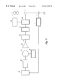
- FIG. 1 is a functional block diagram of a radiotelephony handset implementing the process of the invention
- FIG. 2 is a time chart illustrating a thermal excitation of the battery of the handset
- FIG. 3 is a chart illustrating the steps of the process
- FIG. 4 is a diagram of circuits for measuring the temperature of the battery.
- the radiotelephony handset represented comprises a battery 2 , here of the NiMH type, in series with a breaker 3 , presented in the form of a relay, for controlling the recharging current of the battery 2 , originating from a current generator 1 supplied from the mains and which can be plugged into the handset via a connector.
- a temperature detector 4 Fixed on the battery 2 is a temperature detector 4 and, here specifically, a resistor, or thermistor, of value varying with temperature according to a known law.
- a resistor or thermistor
- a central unit with microprocessor 11 controls the recharging of battery 2 , by operating the relay 3 .
- the central unit comprises at input an analogue/digital converter (ADC) 12 measuring the value of the resistor 4 , for example by measuring its voltage when it is supplied with a determined current.
- ADC analogue/digital converter
- FIG. 4 provides the detail of the measurement circuits and is commented on later.
- the output of the ADC 12 is linked to the positive input of a subtractor 16 receiving, on its negative input, the output of an adder 15 .
- the adder 15 receives the output of a memory 13 providing an ambient temperature value (defined later) and the output of a memory 14 providing a value of a target threshold, limiting the temperature modulation of the battery 2 by the current from the current generator 1 .
- the result output by the subtractor 16 is integrated in an integrator 17 , the result of which is routed, by a router 19 , represented very diagrammatically by a relay blade, to a calculating block 20 or to a calculating block 21 , depending on the control of the router 19 , originating from a sequencer circuit 18 .
- the calculating block 20 calculates the value of the ambient temperature and stores it in memory 13 .
- the expression ambient temperature is understood to mean the temperature of the battery 2 in the absence of recharging current. The ambient temperature therefore depends in particular on the temperature of the ambient air, on the temperature of any surface on which the handset is placed, on its direct exposure to the sun's rays and also on the discharge current in the telephone components, or useful charge, of the handset, which are not represented.
- the calculating block 21 controls, in accordance with the output from the integrator 17 , the breaker 3 so as to limit the mean recharging current to a value such that by itself it only causes heating of the battery 2 not exceeding the threshold value of the memory 14 (or a value tied to the latter, such as proportional), and does so independently of the other causes of heating. It is therefore necessary to be able to discriminate between the heating from the recharging current and that due to the other causes indicated above.
- FIG. 2 illustrates the principle of the process of the invention, the temperature of the battery 2 measured ( 12 ) being plotted as ordinate and the time t as abscissa.
- Curve C 0 represents the profile of the ambient temperature, of the battery 2 , as defined above. This temperature increases here according to a monotonic curve C 0 with substantially constant slope.
- Curve C 1 represents the temperature of the battery 2 actually measured, that is to say the ambient temperature (C 0 ) to which is added a positive modulation or variation due to the fact that the recharging current varies from an initial value, while being applied cyclically, according to successive periods T, to the battery 2 , each time for a charging duration tc followed by a stoppage of duration ta.
- the battery 2 therefore receives cyclic current pulses at determined instants.
- the initial temperature ⁇ 0 (here at a given instant with the thermal regime already established) varies, over the duration tc of the first phase (curve C 2 ), under the effect of the heating due to the recharging current, towards a top asymptotic value parallel to the curve C 0 .
- the heating perceived, which will control the regulation, is strictly speaking the difference between the heating due to the current and the natural cooling during this phase tc.
- the temperature variation is of exponential form, dwindling away as one approaches the asymptote. Added thereto, as absolute variation, is the drift, positive as here or else negative, of the ambient temperature C 0 , going from 0 (arbitrary reference) to ⁇ A 1 .
- Curve C 3 During the second phase ta of rest (curve C 3 ), the thermal excitation of the battery 2 by the recharging current no longer exists and curve C 3 has the “natural” curve C 0 of the ambient as bottom asymptote. Curve C 3 may therefore rise, if curve C 0 rises sufficiently, or else, in the general case represented here, it falls back to a value ⁇ 2 , the ambient temperature having then reached the value ⁇ A 2 . The sawtooth shape of the curves C 2 , C 3 is repeated for the subsequent periods T.
- the ambient temperature C 0 may be regarded, for the sake of explanation, as varying with a time constant which is much greater than the period T, that is to say the curve C 0 is substantially a string of straight line segments, each period T corresponding to a segment.
- the period T here 15 minutes, is however large enough, here of the order of magnitude of the thermal time constant of the battery 2 , for the thermal modulation to be clearly discernible and hence measurable with good accuracy.
- the ambient since the profile of the ambient C 0 does not exhibit any correlation with the controlled thermal modulation, the ambient merely introduces background noise into the calculations, which is filtered by repeating, or integrating, their results.
- Curve C 4 the mean or integral of curves C 2 and C 3 , circumvents the instantaneous effects of the phases tc and ta and is parallel, when the regulating of the current is at equilibrium, to the ambient curve C 0 and above, by ⁇ .
- the temperature offset ⁇ between curves C 0 and C 4 therefore corresponds to an equilibrium between the thermal excitation due to the current, during tc, and the “de-excitation” due to the ambient which then progressively absorbs the thermal overrun of the battery 2 , during ta.
- the thermal excitation power RI 2 ⁇ p (R battery resistance), or thermal heating flux, is equal to the thermal cooling flux, proportional to ⁇ .
- the heating ⁇ represents the value of the resistance R.
- the integral of the thermal flux due to the current during tc is equal to the integral of the cooling during ta.
- RAP thermal shift back towards ambient, during ta.
- the natural cooling of the battery 2 compensates for the introduction of thermal energy.
- This introduction of thermal energy is proportional to the thermal conversion slope, or effectiveness, of the recharging current, to the square of the value I of this current and to the shape factors tc/T and L.
- the values I, tc/T and L being known, ⁇ c is therefore directly indicative of the thermal sensitivity, or conversion slope, of the battery 2 with respect to the recharging current.
- the estimate or fictitious heating EST is a calculated value which is proportional to the actual heating value ⁇ and represents it perfectly. It is therefore sufficient to slave the variable EST to a heating threshold value so as likewise to slave the actual heating ⁇ to a corresponding threshold value.
- the recharging current I is provided by a current generator 1 , adjustment of the instantaneous current of which is not envisaged in this example.
- a current generator 1 adjustment of the instantaneous current of which is not envisaged in this example.
- the current is cut off cyclically in the circuit 38 so as to allow it through in pulses only during the fraction L of the time (relative angle of flow).
- the pulsatile current is equivalent to a direct current (mean current) on which is superimposed an alternating component, the latter can be eliminated, as therefore can the additional heating which it induces, by filtering it through a reactive element downstream of the breaker 3 , such as for example a series inductor.
- FIG. 3 illustrates the regulating process
- the deviation in the slopes is brought into the temperature domain by multiplying by a certain duration, here taken equal to tc.
- the threshold 34 could however have been expressed in the form of a thermal slope with respect to time. This value EST is compared (subtracted), in a step 35 , with a threshold value originating from a memory 34 (equivalent of the memory 14 ).
- the difference obtained is amplified by a factor G in a step 36 so as to provide a utilizable error signal ⁇ which is integrated in a step 37 , over a sliding duration of around T, so as to provide an integrated error signal INT which controls the adjusting of the gate 38 , that is to say fixes the shape factor L, or percentage of time of flow, and hence the mean current.
- the output from the gate 38 is applied to an input of the gate 40 , another input of which receives (step 39 ) a fixed shape factor signal tc/T (here 2/3) originating from the sequencer 18 so as to switch off the breaker 3 during ta.
- the output from the gate 40 controls the breaker 3 and hence the mean recharging current I.L during the phase tc.
- a loop for regulating the rise in the temperature of the battery 2 is thus constructed, circumventing the variations in the ambient.
- the calculating block 21 could be designed to include a comparator for comparing, with an alarm threshold, the deviation ( ⁇ or INT) between the measured temperature modulation and the target value and for controlling an ambient temperature measurement cycle if the deviation exceeds the threshold.
- the value of the temperature modulation is slaved, as explained, to the threshold value, so that the current holds a maximum value, allowing rapid recharging, but remaining compatible with the temperature rise threshold.
- the shape factor F may therefore also increase temporarily, if for example the telephone circuits of the terminal discharge the battery 2 .
- the diagram for measuring the temperature of the battery 2 is represented in FIG. 4 .
- the battery 2 bears a resistor 41 of value specific to the type of battery considered and serving to identify this type. It also bears the resistor 4 , here consisting of a resistor with known negative temperature coefficient (NTC), which coefficient is stored in the central unit.
- NTC negative temperature coefficient
- the battery block ought therefore in principle to include, apart from a pair of supply terminals 50 and 51 , two pairs of measurement terminals for the resistors 4 and 41 , so as to link them to respective circuits with ohmmeter function.
- the battery block comprises only four terminals, that is to say two measurement terminals 52 and 53 in addition to the pair of supply terminals 50 and 51 .
- the resistors 4 and 41 are mounted in series and the dipole thus constructed is linked, on one side, to one of the supply terminals, here earth 50 , and, on the other side, to the measurement terminal 53 .
- the midpoint of the dipole is linked to the other measurement terminal, 52 .
- resistor 41 which is linked to the earth terminal 50 .
- the measurement terminal 53 is linked to the positive supply (terminal 51 ) by a resistor 42 for supplying current to the dipole 4 , 41 .
- a strictly constant current generator could have been provided instead of the resistor 42 .
- a breaker 43 here an analogue gate represented in the form of a relay contact, makes it possible to link the terminal 52 to earth under a low impedance, of a few tens of ohms.
- the A/D converter 12 referenced to earth serving as reference, is linked at input to the terminal 53 and also, by another input, to the terminal 52 .
- the ADC 12 measures the voltage across the terminals of the resistor 41 .
- the latter has a value of 10 kohms, as does the resistor 42 , the NTC resistor, 4 , here having a considerably lower value of a few hundred ohms.
- a value slightly below 6 volts is measured for a battery 2 of nominal value 12 volts.
- the central unit deduces therefrom the type of the battery 2 , that is to say keeps the type whose reference voltage is closest to that measured. This identification makes it possible for example to determine the maximum allowable recharging current during the chemical recharging phase and to limit the shape factor L accordingly.
- the various reference values are sufficiently distinct from one another to tolerate the scatter in battery voltage, the scatter in value of the resistor 41 and the electrical noise.
- This noise stems in particular from the variations in the useful current of the battery 2 across the parasitic resistance of the contact between the terminal 50 and a counterpart earth terminal 50 A of a housing of the casing of the handset reserved for the battery 2 , the dashed line indicating the boundary (four-point connector) of this housing.
- the resistor 41 is also a source of noise.
- the resistor 41 is of low value relative to the resistor 41 , there could even be provision to measure the voltage of the terminal 53 , hence therefore slightly above 6 volts. The terminal 52 would then be unnecessary in this phase and the converter 12 would have just one input.
- a resistor 41 of value specific to the battery 2 , is mounted in series with the current supply circuit 42 to form a divider bridge which is supplied from the battery 2 ,
- the voltage of the terminal 53 of the NTC resistor 4 is measured by earthing the breaker 43 .
- the sensitivity of the ADC 12 can be increased here so as to compensate for the attenuator effect due to the low value of the NTC 4 .
- the resistor 42 here of much higher value, provides an almost constant current, so that the voltage of the terminal 53 , and its variation with temperature, conveys, substantially linearly, the variation in resistance of the NTC 4 , whose temperature dependency curve is stored. However, if the current were to vary with the value of the NTC 4 , the above curve would be corrected accordingly.
- the NTC 4 is thus temporarily linked under low impedance, by the breaker 43 , to an earth which is specific thereto and which virtually short-circuits the electrical noise stemming from the contact 50 , 50 A across the resistor 41 of high value.
- the noise divider bridge 43 - 41 thus isolates the resistor 4 in relation to the above noise generator. Furthermore, it is possible to perform a differential measurement between the two inputs ( 52 , 53 ) of the ADC 12 , so as to eliminate the influence of the parasitic resistance of the breaker 43 .
- the resistive element 4 of temperature-sensitive value is interposed in series, in the middle of the divider bridge, and it is coupled thermally with the battery 2 ,
- the identification resistor 41 is short-circuited through a link of reference potential, 50 A,
- the voltage is measured of a terminal 53 of the resistive element 4 , which terminal is opposite the other terminal 52 at the reference potential, and
- the temperature of the resistive element 4 and hence of the battery 2 is deduced from this, by consulting a pre-established table.
- the mounting of the two resistors 4 and 41 , in the same series circuit, with no galvanic isolation between them, makes it possible to supply them from a common terminal, the single terminal 53 , and the breaker 43 makes it possible to re-establish when need be, the requisite alternative isolation (lost through the disappearance of the galvanic isolation) between the earth contact 50 , 50 A and the variable resistor 4 .
- a series galvanic cutout is thus replaced by a parallel short-circuit.
Landscapes
- Engineering & Computer Science (AREA)
- Power Engineering (AREA)
- Charge And Discharge Circuits For Batteries Or The Like (AREA)
Abstract
Description


Claims (29)
Applications Claiming Priority (3)
| Application Number | Priority Date | Filing Date | Title |
|---|---|---|---|
| FR9808138 | 1998-06-26 | ||
| FR9808138A FR2780570B1 (en) | 1998-06-26 | 1998-06-26 | METHOD FOR CONTROLLING THE RECHARGE OF A BATTERY AND DEVICE FOR CARRYING OUT THE METHOD |
| PCT/FR1999/001532 WO2000001051A1 (en) | 1998-06-26 | 1999-06-25 | Method for controlling a battery recharging and implementing device |
Publications (1)
| Publication Number | Publication Date |
|---|---|
| US6512350B1 true US6512350B1 (en) | 2003-01-28 |
Family
ID=9527912
Family Applications (1)
| Application Number | Title | Priority Date | Filing Date |
|---|---|---|---|
| US09/720,799 Expired - Lifetime US6512350B1 (en) | 1998-06-26 | 1999-06-25 | Method for controlling a battery recharging and implementing device |
Country Status (5)
| Country | Link |
|---|---|
| US (1) | US6512350B1 (en) |
| EP (1) | EP1110295B1 (en) |
| DE (1) | DE69922667T2 (en) |
| FR (1) | FR2780570B1 (en) |
| WO (1) | WO2000001051A1 (en) |
Cited By (3)
| Publication number | Priority date | Publication date | Assignee | Title |
|---|---|---|---|---|
| US20090289497A1 (en) * | 2006-07-18 | 2009-11-26 | Toyota Jidosha Kabushiki Kaisha | Power Supply System, Vehicle with the Same, Temperature Increase Control Method for Power Storage Device and Computer-Readable Recording Medium Bearing Program Causing Computer to Execute Temperature Increase Control of Power Storage Device |
| US20170205468A1 (en) * | 2016-01-14 | 2017-07-20 | Samsung Electronics Co., Ltd. | Battery management apparatus and method |
| US9912185B2 (en) * | 2013-06-06 | 2018-03-06 | Stmicroelectronics (Tours) Sas | Battery life time management |
Families Citing this family (2)
| Publication number | Priority date | Publication date | Assignee | Title |
|---|---|---|---|---|
| FR2813444B1 (en) * | 2000-08-31 | 2002-11-29 | Cit Alcatel | METHOD FOR CHARGING A BATTERY |
| CN112519597B (en) * | 2019-09-17 | 2022-04-26 | 广州汽车集团股份有限公司 | Battery charging method, system, computer device and readable storage medium |
Citations (2)
| Publication number | Priority date | Publication date | Assignee | Title |
|---|---|---|---|---|
| EP0225789A1 (en) | 1985-12-09 | 1987-06-16 | Levitt-Safety Limited | Nicad battery charger |
| WO1996019860A1 (en) | 1994-12-22 | 1996-06-27 | Ing. C. Olivetti & C., S.P.A. | Device and method for charging batteries with a variable current |
-
1998
- 1998-06-26 FR FR9808138A patent/FR2780570B1/en not_active Expired - Lifetime
-
1999
- 1999-06-25 DE DE69922667T patent/DE69922667T2/en not_active Expired - Lifetime
- 1999-06-25 US US09/720,799 patent/US6512350B1/en not_active Expired - Lifetime
- 1999-06-25 WO PCT/FR1999/001532 patent/WO2000001051A1/en not_active Ceased
- 1999-06-25 EP EP99957670A patent/EP1110295B1/en not_active Expired - Lifetime
Patent Citations (2)
| Publication number | Priority date | Publication date | Assignee | Title |
|---|---|---|---|---|
| EP0225789A1 (en) | 1985-12-09 | 1987-06-16 | Levitt-Safety Limited | Nicad battery charger |
| WO1996019860A1 (en) | 1994-12-22 | 1996-06-27 | Ing. C. Olivetti & C., S.P.A. | Device and method for charging batteries with a variable current |
Cited By (5)
| Publication number | Priority date | Publication date | Assignee | Title |
|---|---|---|---|---|
| US20090289497A1 (en) * | 2006-07-18 | 2009-11-26 | Toyota Jidosha Kabushiki Kaisha | Power Supply System, Vehicle with the Same, Temperature Increase Control Method for Power Storage Device and Computer-Readable Recording Medium Bearing Program Causing Computer to Execute Temperature Increase Control of Power Storage Device |
| US7939969B2 (en) * | 2006-07-18 | 2011-05-10 | Toyota Jidosha Kabushiki Kaisha | Power supply system, vehicle with the same, temperature increase control method for power storage device and computer-readable recording medium bearing program causing computer to execute temperature increase control of power storage device |
| US9912185B2 (en) * | 2013-06-06 | 2018-03-06 | Stmicroelectronics (Tours) Sas | Battery life time management |
| US20170205468A1 (en) * | 2016-01-14 | 2017-07-20 | Samsung Electronics Co., Ltd. | Battery management apparatus and method |
| US10444292B2 (en) * | 2016-01-14 | 2019-10-15 | Samsung Electronics Co., Ltd. | Battery management apparatus and method |
Also Published As
| Publication number | Publication date |
|---|---|
| DE69922667T2 (en) | 2005-10-06 |
| DE69922667D1 (en) | 2005-01-20 |
| FR2780570A1 (en) | 1999-12-31 |
| EP1110295B1 (en) | 2004-12-15 |
| WO2000001051A1 (en) | 2000-01-06 |
| FR2780570B1 (en) | 2000-08-04 |
| EP1110295A1 (en) | 2001-06-27 |
Similar Documents
| Publication | Publication Date | Title |
|---|---|---|
| EP0659305B1 (en) | Battery charger | |
| US7405538B1 (en) | Method and system for charging a NiMH or NiCd battery | |
| US5204611A (en) | Charging circuits for rechargeable batteries and cells | |
| CA2103156C (en) | Quick charger and quick charge method of nickel-cadmium battery | |
| US5912547A (en) | Battery charging method and apparatus with thermal mass equalization | |
| CN1998110B (en) | Lithium-ion/polymer lithium battery cell charging method | |
| EP0029743B1 (en) | Method of and apparatus for enabling output power of solar panel to be maximised | |
| EP3828567B1 (en) | Battery management device, battery management method, and battery pack | |
| US20100017155A1 (en) | Battery management system | |
| EP0602177A1 (en) | Apparatus for charging batteries | |
| KR20060052273A (en) | Power control method and power supply device of secondary battery | |
| JP3932675B2 (en) | Battery maximum input / output power estimation device | |
| JPH08329992A (en) | Battery pack and charger | |
| US6512350B1 (en) | Method for controlling a battery recharging and implementing device | |
| JP6826935B2 (en) | Secondary battery internal temperature estimation device and secondary battery internal temperature estimation method | |
| US7129676B2 (en) | Controlling re-charge of a nickel metal-hydride (NiMH) or nickel cadmuim (NiCd) battery | |
| US6232746B1 (en) | Battery charging apparatus and full-charging detecting method | |
| KR20010075142A (en) | Apparatus and method for determining the capacity of a nickel-cadmium battery | |
| GB2359945A (en) | Control of battery charging | |
| EP3872507B1 (en) | Battery management system, battery management method, battery pack, and electric vehicle | |
| JP2004014462A (en) | Remaining battery capacity measurement device | |
| JPH07312229A (en) | Charging device for secondary battery | |
| JPH11355969A (en) | Charging device | |
| JP2581679B2 (en) | Battery monitoring method | |
| JPH0746770A (en) | Charging control circuit |
Legal Events
| Date | Code | Title | Description |
|---|---|---|---|
| AS | Assignment |
Owner name: SAGEM SA, FRANCE Free format text: ASSIGNMENT OF ASSIGNORS INTEREST;ASSIGNORS:BERNARD, ROBERT;LE FICHOUS, PATRICK;ROMAO, FERNANDO;REEL/FRAME:011659/0840 Effective date: 20010314 |
|
| STCF | Information on status: patent grant |
Free format text: PATENTED CASE |
|
| FPAY | Fee payment |
Year of fee payment: 4 |
|
| AS | Assignment |
Owner name: SAGEM COMMUNICATIONS, FRANCE Free format text: ASSIGNMENT OF ASSIGNORS INTEREST;ASSIGNOR:SAGEM SA;REEL/FRAME:021731/0336 Effective date: 20080123 |
|
| AS | Assignment |
Owner name: SAGEM MOBILES, FRANCE Free format text: ASSIGNMENT OF ASSIGNORS INTEREST;ASSIGNOR:SAGEM COMMUNICATION;REEL/FRAME:021744/0307 Effective date: 20070628 |
|
| FEPP | Fee payment procedure |
Free format text: PAYOR NUMBER ASSIGNED (ORIGINAL EVENT CODE: ASPN); ENTITY STATUS OF PATENT OWNER: LARGE ENTITY |
|
| FPAY | Fee payment |
Year of fee payment: 8 |
|
| FPAY | Fee payment |
Year of fee payment: 12 |
|
| AS | Assignment |
Owner name: SAGEM MOBILES, FRANCE Free format text: ASSIGNMENT OF ASSIGNORS INTEREST;ASSIGNOR:SAGEM COMMUNICATION;REEL/FRAME:047140/0003 Effective date: 20070628 |
|
| AS | Assignment |
Owner name: APPLE INC., CALIFORNIA Free format text: ASSIGNMENT OF ASSIGNORS INTEREST;ASSIGNOR:MYRIAD FRANCE;REEL/FRAME:046042/0545 Effective date: 20120726 Owner name: SAGEM WIRELESS, FRANCE Free format text: ASSIGNMENT OF ASSIGNORS INTEREST;ASSIGNOR:SAGEM MOBILES SA;REEL/FRAME:046332/0926 Effective date: 20110511 |