US6510865B2 - Tap and saddle for forming a hinged coupon - Google Patents
Tap and saddle for forming a hinged coupon Download PDFInfo
- Publication number
- US6510865B2 US6510865B2 US09/785,684 US78568401A US6510865B2 US 6510865 B2 US6510865 B2 US 6510865B2 US 78568401 A US78568401 A US 78568401A US 6510865 B2 US6510865 B2 US 6510865B2
- Authority
- US
- United States
- Prior art keywords
- tap
- cutting
- tube
- tubing
- saddle
- Prior art date
- Legal status (The legal status is an assumption and is not a legal conclusion. Google has not performed a legal analysis and makes no representation as to the accuracy of the status listed.)
- Expired - Lifetime
Links
Images


Classifications
-
- F—MECHANICAL ENGINEERING; LIGHTING; HEATING; WEAPONS; BLASTING
- F16—ENGINEERING ELEMENTS AND UNITS; GENERAL MEASURES FOR PRODUCING AND MAINTAINING EFFECTIVE FUNCTIONING OF MACHINES OR INSTALLATIONS; THERMAL INSULATION IN GENERAL
- F16L—PIPES; JOINTS OR FITTINGS FOR PIPES; SUPPORTS FOR PIPES, CABLES OR PROTECTIVE TUBING; MEANS FOR THERMAL INSULATION IN GENERAL
- F16L41/00—Branching pipes; Joining pipes to walls
- F16L41/08—Joining pipes to walls or pipes, the joined pipe axis being perpendicular to the plane of a wall or to the axis of another pipe
- F16L41/16—Joining pipes to walls or pipes, the joined pipe axis being perpendicular to the plane of a wall or to the axis of another pipe the branch pipe comprising fluid cut-off means
-
- F—MECHANICAL ENGINEERING; LIGHTING; HEATING; WEAPONS; BLASTING
- F16—ENGINEERING ELEMENTS AND UNITS; GENERAL MEASURES FOR PRODUCING AND MAINTAINING EFFECTIVE FUNCTIONING OF MACHINES OR INSTALLATIONS; THERMAL INSULATION IN GENERAL
- F16L—PIPES; JOINTS OR FITTINGS FOR PIPES; SUPPORTS FOR PIPES, CABLES OR PROTECTIVE TUBING; MEANS FOR THERMAL INSULATION IN GENERAL
- F16L41/00—Branching pipes; Joining pipes to walls
- F16L41/04—Tapping pipe walls, i.e. making connections through the walls of pipes while they are carrying fluids; Fittings therefor
- F16L41/06—Tapping pipe walls, i.e. making connections through the walls of pipes while they are carrying fluids; Fittings therefor making use of attaching means embracing the pipe
- F16L41/065—Tapping pipe walls, i.e. making connections through the walls of pipes while they are carrying fluids; Fittings therefor making use of attaching means embracing the pipe without removal of material
-
- Y—GENERAL TAGGING OF NEW TECHNOLOGICAL DEVELOPMENTS; GENERAL TAGGING OF CROSS-SECTIONAL TECHNOLOGIES SPANNING OVER SEVERAL SECTIONS OF THE IPC; TECHNICAL SUBJECTS COVERED BY FORMER USPC CROSS-REFERENCE ART COLLECTIONS [XRACs] AND DIGESTS
- Y10—TECHNICAL SUBJECTS COVERED BY FORMER USPC
- Y10T—TECHNICAL SUBJECTS COVERED BY FORMER US CLASSIFICATION
- Y10T137/00—Fluid handling
- Y10T137/0318—Processes
- Y10T137/0402—Cleaning, repairing, or assembling
- Y10T137/0441—Repairing, securing, replacing, or servicing pipe joint, valve, or tank
- Y10T137/0458—Tapping pipe, keg, or tank
- Y10T137/0463—Particular aperture forming means
- Y10T137/0469—Cutter or cutting tool
-
- Y—GENERAL TAGGING OF NEW TECHNOLOGICAL DEVELOPMENTS; GENERAL TAGGING OF CROSS-SECTIONAL TECHNOLOGIES SPANNING OVER SEVERAL SECTIONS OF THE IPC; TECHNICAL SUBJECTS COVERED BY FORMER USPC CROSS-REFERENCE ART COLLECTIONS [XRACs] AND DIGESTS
- Y10—TECHNICAL SUBJECTS COVERED BY FORMER USPC
- Y10T—TECHNICAL SUBJECTS COVERED BY FORMER US CLASSIFICATION
- Y10T137/00—Fluid handling
- Y10T137/598—With repair, tapping, assembly, or disassembly means
- Y10T137/612—Tapping a pipe, keg, or apertured tank under pressure
- Y10T137/6123—With aperture forming means
-
- Y—GENERAL TAGGING OF NEW TECHNOLOGICAL DEVELOPMENTS; GENERAL TAGGING OF CROSS-SECTIONAL TECHNOLOGIES SPANNING OVER SEVERAL SECTIONS OF THE IPC; TECHNICAL SUBJECTS COVERED BY FORMER USPC CROSS-REFERENCE ART COLLECTIONS [XRACs] AND DIGESTS
- Y10—TECHNICAL SUBJECTS COVERED BY FORMER USPC
- Y10T—TECHNICAL SUBJECTS COVERED BY FORMER US CLASSIFICATION
- Y10T408/00—Cutting by use of rotating axially moving tool
- Y10T408/50—Cutting by use of rotating axially moving tool with product handling or receiving means
-
- Y—GENERAL TAGGING OF NEW TECHNOLOGICAL DEVELOPMENTS; GENERAL TAGGING OF CROSS-SECTIONAL TECHNOLOGIES SPANNING OVER SEVERAL SECTIONS OF THE IPC; TECHNICAL SUBJECTS COVERED BY FORMER USPC CROSS-REFERENCE ART COLLECTIONS [XRACs] AND DIGESTS
- Y10—TECHNICAL SUBJECTS COVERED BY FORMER USPC
- Y10T—TECHNICAL SUBJECTS COVERED BY FORMER US CLASSIFICATION
- Y10T408/00—Cutting by use of rotating axially moving tool
- Y10T408/55—Cutting by use of rotating axially moving tool with work-engaging structure other than Tool or tool-support
- Y10T408/561—Having tool-opposing, work-engaging surface
- Y10T408/5628—Tool having screw-thread engaging frame to cause infeed
-
- Y—GENERAL TAGGING OF NEW TECHNOLOGICAL DEVELOPMENTS; GENERAL TAGGING OF CROSS-SECTIONAL TECHNOLOGIES SPANNING OVER SEVERAL SECTIONS OF THE IPC; TECHNICAL SUBJECTS COVERED BY FORMER USPC CROSS-REFERENCE ART COLLECTIONS [XRACs] AND DIGESTS
- Y10—TECHNICAL SUBJECTS COVERED BY FORMER USPC
- Y10T—TECHNICAL SUBJECTS COVERED BY FORMER US CLASSIFICATION
- Y10T408/00—Cutting by use of rotating axially moving tool
- Y10T408/68—Tool or tool-support with thrust-applying machine-engaging screw
Definitions
- This invention relates generally to branch forming attachments and, more specifically, to a tap having a cutting tube for a one-step connection of a branch line to a main line without the aid of tools.
- the attaching device usually comprises two parts, a tap for forming the opening in the pipe and a saddle for holding the main tubing and the branch tubing in fluid communication.
- a tap or cutter having a through passage both cuts a hole and forms a side attachment for the pipe.
- a coupon or plug is cut free of the pipe and is frictionally retained within the cutter so as not to interfere with or block the passageway in the pipe.
- the pipe clamp comprises two identical parts that when snapped together form a threaded recess to allow a user to threadingly drive the coupon cutter through the plastic pipe and position a branch pipe in fluid communication with the main tubing.
- the self tapping branch attachments are particularly well suited for underground irrigation systems that require in situ forming of branch lines to a main tubing, but they are also useful in other systems and other locations that use rigid, resilient or flexible tubing.
- the pipe clamp used in the U.S. Pat. No. 5,694,972 is also shown in U.S. Pat. No. 4,291,855 and comprises two segments that are hinged at an intermediate point to allow the segments to spread apart and receive a pipe.
- the present invention has a hollow tap having a cutting tooth is used to form the side attachment passage but instead of cutting the coupon free of the tubing and retaining the coupon in the cutter the coupon is only partially severed from the pipe.
- the coupon itself forms a living hinge connection to the pipe which retains the coupon in the pipe.
- the partially severing of the coupon minimizes the distortion of the pipe at the junction of the main pipe and the branch pipe, which can lessen the opportunity for leakage.
- the partial severing and retaining of the coupon as an integral living hinge ensures that the coupon will not interfere and block any outlet passages in the main tubing.
- a rigid tubing such as PVC
- the tap will cut the coupon free of the tubing since the more rigid PVC will break rather than flex. In this case the coupon can be flushed free of the tubing.
- the invention comprises a tap having an axially outward extending cutting tooth so that when the cutting tooth is brought into rotational pressure engagement with a resilient tubing the cutting tooth cuts a hole partially through the resilient tubing leaving a coupon integrally hinged but securely attached to the resilient tubing to maintain the coupon in an out-of-the-way condition within the passageway of the resilient tubing.
- U.S. Pat. No. 1,181,131 is a U-bolt pipe saddle with an extra piece required between the main and branch tubing to secure the fit;
- U.S. Pat. No. 3,162,211 shows a device with a cutting needle for forming a hole in a pipe.
- U.S. Pat. No. 3,240,434 shows an irrigation nozzle with a hollow point that is inserted through an opening in the pipe.
- U.S. Pat. No. 3,343,724 shows a similar tap a tap with a needle point and a side port for tapping into the side of a sealed plastic bag.
- U.S. Pat. No. 3,448,758 shows a refrigerator service valve that uses a hollow point that is cut at an angle to insert through a pipe.
- U.S. Pat. No. 3,460,715 shows a tap with a needle point and a side port for tapping into the side of a sealed plastic bag.
- U.S. Pat. No. 3,471,176 is a pipe saddle which does not specify a method for creating the hole for the branch tubing. Most likely, it employs a hand tool;
- U.S. Pat. No. 3,891,150 is a pipe saddle not suited for high-pressure or high-wear situations
- U.S. Pat. No. 3,920,937 shows a drip irrigation system which includes a saddle and sharp pointed tube for extending through a pipe.
- U.S. Pat. No. 3,973,732 shows a quick fitting that is forced through the wall of the tubing.
- U.S. Pat. No. 4,239,265 is a pipe saddle requiring four steps and four different parts as well as a sealing ring;
- U.S. Pat. No. 4,291,855 shows a pipe clamp having hinged portions for securing around a pipe.
- U.S. Pat. No. 4,789,189 is a metal pipe saddle requiring a cutting tool to make a branch hole, and another device to reseal the hole.
- U.S. Pat. No. 5,105,844 shows a two step branch forming attachment with a cutter for cutting a coupon from a main pipe.
- U.S. Pat. No. 5,169,177 shows a saddle for mounting around a tube.
- FIG. 1 is an end view of the coupon cutter and saddle secured to a main pipe
- FIG. 2 is side view of the coupon cutter and saddle of FIG. 1;
- FIG. 3 is a front elevation view of the cutting end of the cutting tube of FIG. 1;
- FIG. 4 is a side elevation view of the cutting end of the cutting tube of FIG. 1;
- FIG. 5 is an end view of the of the cutting end of the cutting tube of FIG. 1;
- FIG. 6 is end view of the saddle strap and latch in the unlatched condition
- FIG. 7 is a partial cut-away front elevation view of the tap of FIG. 1;
- FIG. 8 is a top view of the tap shown in FIG. 7;
- FIG. 9 is perspective view of the saddle of FIG. 1 in a latched condition
- FIG. 10 is an elevation showing the cutting tube and the hinged coupons
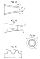
- FIG. 11 is a side view of one embodiment of a cutting tube
- FIG. 12 is an end view of the cutting tube of FIG. 11;
- FIG. 13 is a side view of the cutting tube of FIG. 11;
- FIG. 14 is a partial side view of a cutting tube with two cutting teeth
- FIG. 15 is an end view of the cutting tube of FIG. 14.
- FIG. 16 shows the cutting tube laid out in a plane view.
- FIG. 1 shows a partial end view of a tap 11 positioned within a saddle 12 that has a flexible strap or band 14 that extends circumferentially around a resilient tubing 16 and FIG. 2 shows a side view of tap 11 rotatingly engaged in saddle 12 .
- Tap 11 includes a male thread 20 for rotating engagement with a female thread 21 located in housing 24 of saddle 12 .
- a branch tube 15 extends outwardly from resilient tubing 16 .
- Tap 11 includes a cutting tube 13 that extends through a sidewall of resilient tubing 16 .
- a first integral coupon 17 a extends inwardly from resilient tubing 16 and a second integral coupon 17 extends radially inward from the sidewall of resilient tubing 16 .
- the coupons 17 and 17 a are integrally connected to resilient tubing 16 and are formed from a part of resilient tubing 16 . That is, the cutting tube 13 partially cuts a hole through the sidewall of resilient tubing 16 and then forces the partially-severed coupon or coupons outwardly away from the cutting tube without severing the coupon from the tubing 16 .
- FIG. 3 shows an enlarged elevation view of the end of cutting tube 13 .
- Cutting tube 13 includes a cylindrical sealing surface 13 a which adjoins one end of a frusto conical section 13 b .
- the opposite end of frusto conical section 13 includes a first circumferential, axially outwardly extending tooth 13 c and a second circumferentially axially outwardly extend tooth 13 d .
- the tooth 13 c extends axially outwardly a distance t 2 from tooth root surface 32 and tooth root surface 33 with the dimension t 2 greater than the distance t 1 that tooth 13 d extends outwardly. Both teeth have an arcuate shape and follow a portion of the annular end of cutting tube
- FIG. 4 shows a side view of cutting tube, which is shown in FIG. 3, revealing an inlet 26 for entry of fluids into the passageway 9 located within hollow cutting tube 13 .
- the cutting teeth 13 c and 13 d extend upwardly with the angle of the cutting teeth flowing from the converging angle of the frusto conical section 13 b .
- the length L 3 of the frusto conical section and the diameter expansion D 1 to D 2 is such that the resilient tubing that is to receive the cutting tube is sufficiently expanded to create a radial inward pressure to seal the resilient tubing to the cutting tube but not sufficiently great so as to distort the resilient tubing and create opportunities for leakage.
- An operator can select the amount of diametrical expansion of the tubing based on the type of resilient tubing as well as the size of the cutting tube in order to obtain maximum sealing capacity.
- the length of the taper can be selected based on the force needed to expand the resilient tubing. For example, a longer taper provides a gradual expansion of the hole and requires less force while a shorter taper provides for an abrupt expansion of the hole and requires greater force.
- one of the teeth 13 c and 13 d cuts the tubing while the other assists in forcing the tooth off to the side in a hinged coupon.
- FIG. 5 shows an end view of the cutting tube 13 revealing the cutting tooth 13 c extending circumferentially around the end of cutting tube 13 to form a arcuate teeth having a partial annular shape.
- Located on one end of cutting tooth 13 c is a leading edge 30 that forms a cutting edge for rotational penetration of the cutting tooth 13 c through a sidewall of a resilient tubing.
- the second cutting tooth 13 d positioned on the opposite side and extending in a partial circumferential distance around the end of cutting tube 13 is the second cutting tooth 13 d which has a leading edge 32 that forms a cutting edge for rotational penetration of the cutting tooth 13 c through a sidewall of the resilient tubing.
- the curved outward ends of cutting teeth 13 c and 13 d are shown with a flat edge or blunt edge.
- FIG. 6 shows an end or side view of one-piece saddle 12 showing the strap 14 in an unlatched condition with latch member 14 a in disengagement with latch member 14 b .
- the strap or band 14 comprises two portions, a flexible material which extends upward to 14 e which is enlarged and reinforced to provide a stiffer section to maintain the curved shape of the elongated sealing seat 14 c .
- the portion of the band extending clockwise from reinforcing member 14 e retains the flexibility allowing the band 14 to slip over the exterior of a resilient tubing.
- the resilient tubing can be laterally positioned within the interior of band 14 . Once in position the band 14 can be secured to hold the band on the resilient tubing.
- the band or strap 14 can be made from plastic materials such as polypropylene.
- FIG. 7 shows an isolated front view of a one-piece tap 11 showing drum 44 having an external male thread 45 and an internal female thread 46 .
- Cutting tube 13 which is concentric with drum 44 , extends axially outward from drum 44 with one end integral with drum 44 and the other end containing integral cutting tooth 13 c proximate inlet 27 .
- the external male threads permit threaded engagement with the saddle and the internal threads 46 permit one to secure a branch pipe to tap 11 .
- Located on the top of tap 11 is a handgrip 48 .
- FIG. 8 shows a top view of tap 11 showing handgrip 48 includes a pair of ears 48 a and 48 b to enable a user to grasp and rotate tap 11 by hand.
- handgrip 48 includes a pair of ears 48 a and 48 b to enable a user to grasp and rotate tap 11 by hand.
- a user grasps handgrip 48 with one hand and rotates handgrip 48 to screw thread 44 into the housing which forces cutting tube 13 axially downward into a sidewall of a resilient tubing.
- Continued rotation of handgrip 48 causes cutting tube 13 to cut a partial hole through a resilient tubing.
- the cutting tooth creates a hinged coupon or coupons on the inside of the resilient tubing.
- the longer tooth cuts the tubing while the following tooth rolls the coupon clear of the cutting tooth to leave a hinged coupon therein; however, the dynamics of penetration are such that either tooth could cut or roll the material to form the hinged coupon.
- the cutting tube 13 results in the coupon from the resilient tubing being deflected inward away from the cutting tooth.
- This partial severing of the coupon ensures that the coupon can be retained in an out-of-the-way condition.
- the resilient tubing is flexible the coupon forms its own integral hinge allowing the coupon to be forced inwardly into the resilient tubing as shown in FIG. 1 .
- the presence of the coupon integrally hinged from a sidewall of the resilient tubing does not interfere with forming a fluid tight seal between the cylindrical sealing surface and the resilient tubing.
- the amount of the distortion of the resilient tubing is decreased by the forming of an opening in the sidewall of the resilient tubing the chances of distortion producing leaks are reduced.
- FIG. 9 is a pictorial view of the one-piece saddle 11 revealing the housing 24 having a triangular shaped, locking stop 24 a thereon for engagement a tab on the tap.
- the seating region 14 c is shown extending crosswise across the saddle with an opening 40 therein for cutting tube 13 .
- a hook shaped latch 14 b and hook shaped latch 14 a are shown in the latched condition. Latch 14 b and 14 a can be unlatched by flexing of strap 14 .
- FIG. 10 shows tap 11 without the saddle 12 present.
- saddle 12 holds tap 11 in the position shown in FIG. 10 and is used to drive the tap into the resilient tubing.
- To position tap 11 in the position shown in FIG. 10 one would rotate tap 11 until the cutting teeth 13 c and 13 d penetrated the resilient sidewall 16 b of resilient tubing 16 .
- a first integral coupon 17 a hinges inwardly into resilient tubing 16 and a second integral coupon 17 b hinges inwardly inward to resilient tubing 16 .
- the number of hinged coupons can vary and in some cases only a single hinged coupon with be formed and in other cases a plurality of hinged coupons are formed.
- the hinged coupons With the hinged coupons extending inward the cylindrical sealing surface 13 forms a circumferential seal 16 a around the sidewall the opening in sidewall 16 s of resilient tubing 16 . That is the resilient tubing 14 compressively squeezes against cylindrical sealing surface 16 with sufficient compression to form a fluid tight seal between the resilient tubing and the cylindrical sealing surface 13 . Surprisingly, the hinged coupons which extend from the sidewall of the resilient tubing do not interfere with the forming of the fluid tight seal. As the opening in the side wall is circular the tubing can squeeze more uniformly around the cutting tube 13 than if the hole were punched through the tubing, thus providing less distortion, which can lead to premature leaks.
- FIG. 11 shows an alternate preferred embodiment a cutting tube for generating hinged coupon.
- Cutting tube 53 contains a single cutting tooth 54 that extends a distance L outward from frusto conical section 59 .
- the cutting tube 53 includes a slight diametrical expansion to further aid informing a fluid tight seal between the cutting tube and the resilient tubing.
- FIG. 12 shows an end view of cutting tube 53 showing the curved single cutting tooth 55 extending circumferential around a portion of the end of the cutting tube 53 .
- the Length of the cutting tooth is identified by the dimension W.
- FIG. 13 shows a sectional view of cutting tube 53 taken along lines 13 — 13 of FIG. 11 .
- Single tooth 54 extends axially outwardly with the edge of tooth identified by numeral 55 .
- the cutting tube 53 can be attached to the drum as shown in FIG. 7 to provide for an operator to rotate cutting tool 53 into the resilient tubing.
- FIG. 14 shows an alternate preferred embodiment wherein cutting tube 53 incudes a first cutting tooth 60 and a second cutting tooth 61 which are of substantially the same length.
- a coupon can be partially severed; however, the rotation of the cutting tube should be at sufficiently slow rate so as not to sever the coupon before the coupon is forced out of the way.
- FIG. 15 shows that each of the curved cutting teeth 60 and 61 extend partially around the circumferential end of cutting tube 53 .
- FIG. 16 is a plane view of the cutting tool teeth 60 and 61 as they would appear if the cutting tool teeth were unwound from the cylindrical cutting tube and laid in a flat condition.
- the edge 62 is slightly tapered.
- the cutting teeth 60 and 61 extend axially outward to provide an undulating cutting area. It has been found that by using an extending cutting tooth and hand rotation one can rotationally carve a hole in a resilient tubing one does not fully cut through the resilient tubing leaving an integral hinged coupon or coupons.
- the actual speed of rotation of the cutting tube 53 depends on the material and the thickness of the material and can be readily determined by forming a hole in a piece of waste pipe. In most instance one can not turn the cutting tube fast enough to completely sever the coupon. Once the person understands the needed rate of rotation it is easy for the user to cut the coupons with an integral hinge using the embodiment of FIGS. 14-16.
- FIG. 1 illustrates that in some condition the coupon may split into two parts and a portion of the coupon 17 can be hinged from one side and a second portion of the coupon 17 a can be hinged from another area of the tube.
- the tubing could be non-resilient so that the coupon or coupons might break free of the tubing. If the coupons break as the hole is cut the coupons cut while forming the openings in the pipe could be flushed from the line when the line is flushed prior to actual use of the system.
Landscapes
- Engineering & Computer Science (AREA)
- General Engineering & Computer Science (AREA)
- Mechanical Engineering (AREA)
- Branch Pipes, Bends, And The Like (AREA)
Abstract
Description
Claims (32)
Priority Applications (2)
| Application Number | Priority Date | Filing Date | Title |
|---|---|---|---|
| US09/785,684 US6510865B2 (en) | 2000-02-18 | 2001-02-16 | Tap and saddle for forming a hinged coupon |
| US09/918,131 US6601605B2 (en) | 2000-02-18 | 2001-07-30 | Locking end cap |
Applications Claiming Priority (2)
| Application Number | Priority Date | Filing Date | Title |
|---|---|---|---|
| US18361200P | 2000-02-18 | 2000-02-18 | |
| US09/785,684 US6510865B2 (en) | 2000-02-18 | 2001-02-16 | Tap and saddle for forming a hinged coupon |
Related Child Applications (1)
| Application Number | Title | Priority Date | Filing Date |
|---|---|---|---|
| US09/918,131 Continuation-In-Part US6601605B2 (en) | 2000-02-18 | 2001-07-30 | Locking end cap |
Publications (2)
| Publication Number | Publication Date |
|---|---|
| US20010032667A1 US20010032667A1 (en) | 2001-10-25 |
| US6510865B2 true US6510865B2 (en) | 2003-01-28 |
Family
ID=26879345
Family Applications (1)
| Application Number | Title | Priority Date | Filing Date |
|---|---|---|---|
| US09/785,684 Expired - Lifetime US6510865B2 (en) | 2000-02-18 | 2001-02-16 | Tap and saddle for forming a hinged coupon |
Country Status (1)
| Country | Link |
|---|---|
| US (1) | US6510865B2 (en) |
Cited By (17)
| Publication number | Priority date | Publication date | Assignee | Title |
|---|---|---|---|---|
| US20040113425A1 (en) * | 2002-05-03 | 2004-06-17 | King Thomas A | Saddle tee and tap for irrigation lines |
| US20060065306A1 (en) * | 2004-09-27 | 2006-03-30 | Mortensen Mark A | Removable, snap-on saddle and tap for irrigation pipes |
| US20060169805A1 (en) * | 2005-01-28 | 2006-08-03 | Rajiv Dabir | Saddle tee and tool for irrigation lines |
| US20090140516A1 (en) * | 2007-11-29 | 2009-06-04 | King Jr L Herbert | Pipe saddle |
| US7832420B2 (en) | 2007-12-07 | 2010-11-16 | Orbit Irrigation Products, Inc. | Saddle tee |
| US20110067499A1 (en) * | 2009-09-22 | 2011-03-24 | Lawrence Jason A | Method and Template for Producing a Tensile Test Coupon |
| WO2011037906A1 (en) * | 2009-09-22 | 2011-03-31 | Mcelroy Manufacturing, Inc. | Method and template for producing a tensile test coupon |
| US8172276B1 (en) | 2006-10-06 | 2012-05-08 | Blazing Products, Inc. | Fittings connectable to end portions of pipes and related methods |
| US8662541B2 (en) | 2009-04-01 | 2014-03-04 | Blazing Products, Inc. | Fittings for sealed retention to end portions of pipes and related methods |
| US9297486B2 (en) | 2006-10-06 | 2016-03-29 | Blazing Products, Inc. | Pipe fittings with insert retaining seals and related methods |
| US9593789B2 (en) | 2006-10-06 | 2017-03-14 | Blazing Products, Inc. | Pipe-fitting with adaptor assembly and related methods |
| US9661807B2 (en) | 2012-05-24 | 2017-05-30 | Rain Bird Corporation | Conduit with connector and assembly thereof |
| US9668431B2 (en) | 2013-11-22 | 2017-06-06 | Rain Bird Corporation | Conduit with connector and assembly thereof |
| US20170175939A1 (en) * | 2011-03-01 | 2017-06-22 | National Diversified Sales, Inc. | Clamp and spike for flexible conduit |
| US10537073B2 (en) | 2012-05-24 | 2020-01-21 | Rain Bird Corporation | Conduit with connector and assembly thereof |
| US10801654B2 (en) | 2006-10-06 | 2020-10-13 | King Technology Of Missouri, Llc | Tubular pipe fitting insert with interior reinforcement ribs |
| WO2025207309A1 (en) * | 2024-03-29 | 2025-10-02 | Nelson Irrigation Corporation | Hose barb effecting reductions in pressure loss |
Families Citing this family (2)
| Publication number | Priority date | Publication date | Assignee | Title |
|---|---|---|---|---|
| US7549359B2 (en) * | 2007-06-11 | 2009-06-23 | Gas Technology Institute | Aldyl a tee scraper |
| GB2536960B (en) | 2015-04-02 | 2021-02-24 | Exel Industries Sa | Irrigation connectors |
Citations (27)
| Publication number | Priority date | Publication date | Assignee | Title |
|---|---|---|---|---|
| US1370739A (en) * | 1921-03-08 | Detachable spout | ||
| US3495615A (en) | 1967-07-27 | 1970-02-17 | Sealed Unit Parts Co Inc | Debrisless tap valve |
| US3509905A (en) * | 1967-11-15 | 1970-05-05 | John W Mullins | Line clamping self-tapping service valve |
| US3554217A (en) * | 1969-04-21 | 1971-01-12 | Sealed Unit Parts Co Inc | Self-tapping valve |
| US3580269A (en) * | 1969-04-29 | 1971-05-25 | Sealed Unit Parts Co Inc | Debrisless tap valve with backraked piercing element |
| US3756267A (en) | 1970-10-28 | 1973-09-04 | W Hutton | Service tap tool |
| US3762263A (en) * | 1971-02-15 | 1973-10-02 | F Bocceda | Device for making holes in pipes |
| US4112944A (en) * | 1976-12-13 | 1978-09-12 | Williams Gayland M | Tube clamp and piercing device |
| US4364406A (en) * | 1979-05-22 | 1982-12-21 | Bohlin Jan O | Method and device for establishing a flow connection with a pipe |
| US4434809A (en) * | 1979-12-06 | 1984-03-06 | Rogstadius John I F | Pipe coupling |
| US4522339A (en) * | 1983-06-03 | 1985-06-11 | Ris Irrigation Systems | Irrigation fitting with installation barb and associated barb installation tool |
| US4540011A (en) * | 1982-08-25 | 1985-09-10 | Hotpoint Limited | Method and device for forming a branch connection in a pipe |
| US4574443A (en) | 1984-06-21 | 1986-03-11 | Exxon Research And Engineering Co. | Pipe punch device |
| US5076318A (en) | 1990-08-23 | 1991-12-31 | Phillips Petroleum Company | Tapping tee cutter for plastic pipe |
| US5105844A (en) | 1990-09-24 | 1992-04-21 | King Lloyd H Sr | Two step branch forming attachment |
| US5241981A (en) | 1992-05-07 | 1993-09-07 | Conbraco Industries, Inc. | Self-tapping pressure relief valve |
| US5345964A (en) | 1992-05-30 | 1994-09-13 | Friatec Ag Keramik- Und Kunststoffwerke | Pipe piercing fitting and valve |
| US5425395A (en) | 1994-09-13 | 1995-06-20 | Perfection Corporation | Tapping tee assembly |
| US5577529A (en) | 1995-01-19 | 1996-11-26 | Plasson Maagan Michael Industries Ltd. | Tapping fittings |
| US5609181A (en) * | 1996-04-02 | 1997-03-11 | Evans; Donald L. | Tube connector and tapping device |
| US5694972A (en) | 1996-06-27 | 1997-12-09 | Tom King Harmony Products, Inc. | Saddle tee for irrigation lines |
| US5732732A (en) | 1995-07-09 | 1998-03-31 | Plasson Maagan Michael Industries Ltd | Tapping fitting |
| US5896885A (en) | 1996-06-11 | 1999-04-27 | Phillips Petroleum Company | Tapping saddle pipe fitting |
| US5964240A (en) | 1998-06-15 | 1999-10-12 | Pressurised Pipe Connectors Ltd | Pipe tapping |
| US5967168A (en) | 1997-04-10 | 1999-10-19 | Waterworks Technology Development Organization Co., Ltd. | Method of connecting branch pipe |
| US6012475A (en) | 1998-06-03 | 2000-01-11 | Delta Engineering Holdings Limited | Self-piercing valve assembly |
| US6216723B1 (en) | 1999-11-05 | 2001-04-17 | Tom King Harmony Products, Inc. | Self-tapping tee |
-
2001
- 2001-02-16 US US09/785,684 patent/US6510865B2/en not_active Expired - Lifetime
Patent Citations (27)
| Publication number | Priority date | Publication date | Assignee | Title |
|---|---|---|---|---|
| US1370739A (en) * | 1921-03-08 | Detachable spout | ||
| US3495615A (en) | 1967-07-27 | 1970-02-17 | Sealed Unit Parts Co Inc | Debrisless tap valve |
| US3509905A (en) * | 1967-11-15 | 1970-05-05 | John W Mullins | Line clamping self-tapping service valve |
| US3554217A (en) * | 1969-04-21 | 1971-01-12 | Sealed Unit Parts Co Inc | Self-tapping valve |
| US3580269A (en) * | 1969-04-29 | 1971-05-25 | Sealed Unit Parts Co Inc | Debrisless tap valve with backraked piercing element |
| US3756267A (en) | 1970-10-28 | 1973-09-04 | W Hutton | Service tap tool |
| US3762263A (en) * | 1971-02-15 | 1973-10-02 | F Bocceda | Device for making holes in pipes |
| US4112944A (en) * | 1976-12-13 | 1978-09-12 | Williams Gayland M | Tube clamp and piercing device |
| US4364406A (en) * | 1979-05-22 | 1982-12-21 | Bohlin Jan O | Method and device for establishing a flow connection with a pipe |
| US4434809A (en) * | 1979-12-06 | 1984-03-06 | Rogstadius John I F | Pipe coupling |
| US4540011A (en) * | 1982-08-25 | 1985-09-10 | Hotpoint Limited | Method and device for forming a branch connection in a pipe |
| US4522339A (en) * | 1983-06-03 | 1985-06-11 | Ris Irrigation Systems | Irrigation fitting with installation barb and associated barb installation tool |
| US4574443A (en) | 1984-06-21 | 1986-03-11 | Exxon Research And Engineering Co. | Pipe punch device |
| US5076318A (en) | 1990-08-23 | 1991-12-31 | Phillips Petroleum Company | Tapping tee cutter for plastic pipe |
| US5105844A (en) | 1990-09-24 | 1992-04-21 | King Lloyd H Sr | Two step branch forming attachment |
| US5241981A (en) | 1992-05-07 | 1993-09-07 | Conbraco Industries, Inc. | Self-tapping pressure relief valve |
| US5345964A (en) | 1992-05-30 | 1994-09-13 | Friatec Ag Keramik- Und Kunststoffwerke | Pipe piercing fitting and valve |
| US5425395A (en) | 1994-09-13 | 1995-06-20 | Perfection Corporation | Tapping tee assembly |
| US5577529A (en) | 1995-01-19 | 1996-11-26 | Plasson Maagan Michael Industries Ltd. | Tapping fittings |
| US5732732A (en) | 1995-07-09 | 1998-03-31 | Plasson Maagan Michael Industries Ltd | Tapping fitting |
| US5609181A (en) * | 1996-04-02 | 1997-03-11 | Evans; Donald L. | Tube connector and tapping device |
| US5896885A (en) | 1996-06-11 | 1999-04-27 | Phillips Petroleum Company | Tapping saddle pipe fitting |
| US5694972A (en) | 1996-06-27 | 1997-12-09 | Tom King Harmony Products, Inc. | Saddle tee for irrigation lines |
| US5967168A (en) | 1997-04-10 | 1999-10-19 | Waterworks Technology Development Organization Co., Ltd. | Method of connecting branch pipe |
| US6012475A (en) | 1998-06-03 | 2000-01-11 | Delta Engineering Holdings Limited | Self-piercing valve assembly |
| US5964240A (en) | 1998-06-15 | 1999-10-12 | Pressurised Pipe Connectors Ltd | Pipe tapping |
| US6216723B1 (en) | 1999-11-05 | 2001-04-17 | Tom King Harmony Products, Inc. | Self-tapping tee |
Cited By (29)
| Publication number | Priority date | Publication date | Assignee | Title |
|---|---|---|---|---|
| US20040113425A1 (en) * | 2002-05-03 | 2004-06-17 | King Thomas A | Saddle tee and tap for irrigation lines |
| US7150476B2 (en) * | 2002-05-03 | 2006-12-19 | Blazing Products, Inc. | Saddle tee and tap for irrigation lines |
| US20060065306A1 (en) * | 2004-09-27 | 2006-03-30 | Mortensen Mark A | Removable, snap-on saddle and tap for irrigation pipes |
| US7150289B2 (en) | 2004-09-27 | 2006-12-19 | Duane D. Robertson | Removable, snap-on saddle and tap for irrigation pipes |
| US20060169805A1 (en) * | 2005-01-28 | 2006-08-03 | Rajiv Dabir | Saddle tee and tool for irrigation lines |
| US7219684B2 (en) | 2005-01-28 | 2007-05-22 | Rain Bird Corporation | Saddle tee and tool for irrigation lines |
| US9593789B2 (en) | 2006-10-06 | 2017-03-14 | Blazing Products, Inc. | Pipe-fitting with adaptor assembly and related methods |
| US10801654B2 (en) | 2006-10-06 | 2020-10-13 | King Technology Of Missouri, Llc | Tubular pipe fitting insert with interior reinforcement ribs |
| US8596691B2 (en) | 2006-10-06 | 2013-12-03 | Blazing Products, Inc. | Fittings connectable to end portions of pipes and related methods |
| US9297486B2 (en) | 2006-10-06 | 2016-03-29 | Blazing Products, Inc. | Pipe fittings with insert retaining seals and related methods |
| US8172276B1 (en) | 2006-10-06 | 2012-05-08 | Blazing Products, Inc. | Fittings connectable to end portions of pipes and related methods |
| USD709994S1 (en) | 2007-10-05 | 2014-07-29 | Blazing Products, Inc. | Insert portion of a pipe fitting |
| US20090140516A1 (en) * | 2007-11-29 | 2009-06-04 | King Jr L Herbert | Pipe saddle |
| US7832420B2 (en) | 2007-12-07 | 2010-11-16 | Orbit Irrigation Products, Inc. | Saddle tee |
| US8196599B2 (en) | 2007-12-07 | 2012-06-12 | Orbit Irrigation Products, Inc. | Saddle tee |
| US20110127764A1 (en) * | 2007-12-07 | 2011-06-02 | Scot Hoskisson | Saddle tee |
| US8662541B2 (en) | 2009-04-01 | 2014-03-04 | Blazing Products, Inc. | Fittings for sealed retention to end portions of pipes and related methods |
| US8365429B2 (en) | 2009-09-22 | 2013-02-05 | Lawrence Jason A | Method and template for producing a tensile test coupon |
| CN102665981A (en) * | 2009-09-22 | 2012-09-12 | 麦克瑞制造公司 | Method and template for producing a tensile test coupon |
| CN102665981B (en) * | 2009-09-22 | 2015-05-13 | 麦克瑞制造公司 | Method and template for producing a tensile test coupon |
| US8371036B2 (en) | 2009-09-22 | 2013-02-12 | Jason A. Lawrence | Method and template for producing a tensile test coupon |
| WO2011037906A1 (en) * | 2009-09-22 | 2011-03-31 | Mcelroy Manufacturing, Inc. | Method and template for producing a tensile test coupon |
| US20110067499A1 (en) * | 2009-09-22 | 2011-03-24 | Lawrence Jason A | Method and Template for Producing a Tensile Test Coupon |
| US20170175939A1 (en) * | 2011-03-01 | 2017-06-22 | National Diversified Sales, Inc. | Clamp and spike for flexible conduit |
| US10161553B2 (en) * | 2011-03-01 | 2018-12-25 | National Diversified Sales, Inc. | Clamp and spike for flexible conduit |
| US9661807B2 (en) | 2012-05-24 | 2017-05-30 | Rain Bird Corporation | Conduit with connector and assembly thereof |
| US10537073B2 (en) | 2012-05-24 | 2020-01-21 | Rain Bird Corporation | Conduit with connector and assembly thereof |
| US9668431B2 (en) | 2013-11-22 | 2017-06-06 | Rain Bird Corporation | Conduit with connector and assembly thereof |
| WO2025207309A1 (en) * | 2024-03-29 | 2025-10-02 | Nelson Irrigation Corporation | Hose barb effecting reductions in pressure loss |
Also Published As
| Publication number | Publication date |
|---|---|
| US20010032667A1 (en) | 2001-10-25 |
Similar Documents
| Publication | Publication Date | Title |
|---|---|---|
| US6510865B2 (en) | Tap and saddle for forming a hinged coupon | |
| US5105844A (en) | Two step branch forming attachment | |
| US20150144717A1 (en) | Conduit With Connector And Assembly Thereof | |
| US6681796B2 (en) | Drainage valve pipe tap assembly | |
| US10537073B2 (en) | Conduit with connector and assembly thereof | |
| US5694972A (en) | Saddle tee for irrigation lines | |
| US4522339A (en) | Irrigation fitting with installation barb and associated barb installation tool | |
| US7721754B2 (en) | Tapping tee assembly with cap assembly | |
| US8109539B2 (en) | Variable joining device and method for its use | |
| BR112012017682B1 (en) | CONNECTION FOR VALVES | |
| US4029118A (en) | Tapping apparatus and method | |
| US20040080158A1 (en) | Pipe saddle | |
| US9661807B2 (en) | Conduit with connector and assembly thereof | |
| US6601605B2 (en) | Locking end cap | |
| US5609181A (en) | Tube connector and tapping device | |
| US8998270B2 (en) | Threaded adaptor | |
| EP1249658A1 (en) | Tap and saddle for forming a hinged coupon | |
| EP1564474B1 (en) | No interrupt service tee and method | |
| US5662358A (en) | Branch-off connection | |
| US6231083B1 (en) | Coupling assembly for selected orientation | |
| US5240290A (en) | Adapter assembly for branching a pipe | |
| JPH06159578A (en) | Branched coupler for piping of thermoplastic material | |
| US5178421A (en) | Garden hose mender | |
| US20090218808A1 (en) | Improved duct coupling system | |
| CN116507843A (en) | Integrated Joint System for Fluid Distribution Tubular Elements |
Legal Events
| Date | Code | Title | Description |
|---|---|---|---|
| AS | Assignment |
Owner name: KING TECHNOLOGY OF MISSOURI, INC., MISSOURI Free format text: ASSIGNMENT OF ASSIGNORS INTEREST;ASSIGNORS:KING, JR., LLOYD HERBERT;HOFFMAN, GLENN M.;REEL/FRAME:011567/0359 Effective date: 20010216 |
|
| STCF | Information on status: patent grant |
Free format text: PATENTED CASE |
|
| FPAY | Fee payment |
Year of fee payment: 4 |
|
| FPAY | Fee payment |
Year of fee payment: 8 |
|
| FPAY | Fee payment |
Year of fee payment: 12 |
|
| AS | Assignment |
Owner name: THE PATENT STORE LLC, MISSOURI Free format text: ASSIGNMENT OF ASSIGNORS INTEREST;ASSIGNOR:KING TECHNOLOGY OF MISSOURI, INC.;REEL/FRAME:045865/0538 Effective date: 20180518 |
|
| AS | Assignment |
Owner name: ROYAL BANK OF CANADA, AS ADMINISTRATIVE AGENT, CANADA Free format text: FIRST LIEN INTELLECTUAL PROPERTY SECURITY AGREEMENT;ASSIGNOR:KING TECHNOLOGY OF MISSOURI, LLC;REEL/FRAME:046216/0193 Effective date: 20180522 Owner name: ROYAL BANK OF CANADA, AS ADMINISTRATIVE AGENT, CAN Free format text: FIRST LIEN INTELLECTUAL PROPERTY SECURITY AGREEMENT;ASSIGNOR:KING TECHNOLOGY OF MISSOURI, LLC;REEL/FRAME:046216/0193 Effective date: 20180522 |
|
| AS | Assignment |
Owner name: WILMINGTON TRUST, NATIONAL ASSOCIATION, AS ADMINISTRATIVE AGENT, DELAWARE Free format text: SECURITY INTEREST;ASSIGNOR:KING TECHNOLOGY OF MISSOURI, LLC;REEL/FRAME:045897/0977 Effective date: 20180522 Owner name: WILMINGTON TRUST, NATIONAL ASSOCIATION, AS ADMINIS Free format text: SECURITY INTEREST;ASSIGNOR:KING TECHNOLOGY OF MISSOURI, LLC;REEL/FRAME:045897/0977 Effective date: 20180522 |
|
| AS | Assignment |
Owner name: KING TECHNOLOGY OF MISSOURI, LLC, MISSOURI Free format text: TERMINATION AND RELEASE OF SECURITY INTEREST IN INTELLECTUAL PROPERTY;ASSIGNOR:ROYAL BANK OF CANADA;REEL/FRAME:046761/0595 Effective date: 20180809 Owner name: KING TECHNOLOGY OF MISSOURI, LLC, MISSOURI Free format text: TERMINATION AND RELEASE OF SECURITY INTEREST IN SECOND LIEN INTELLECTUAL PROPERTY COLLATERAL;ASSIGNOR:WILMINGTON TRUST, NATIONAL ASSOCIATION, AS ADMINISTRATIVE AGENT;REEL/FRAME:046762/0718 Effective date: 20180809 |
|
| AS | Assignment |
Owner name: JPMORGAN CHASE BANK, N.A., ILLINOIS Free format text: SECURITY INTEREST;ASSIGNOR:THE PATENT STORE, LLC;REEL/FRAME:048141/0202 Effective date: 20190123 |
|
| AS | Assignment |
Owner name: THE PATENT STORE, LLC, MISSOURI Free format text: CORRECTIVE ASSIGNMENT TO CORRECT THE CORRECT ASSIGNEE PREVIOUSLY RECORDED AT REEL: 045865 FRAME: 0538. ASSIGNOR(S) HEREBY CONFIRMS THE ASSIGNMENT;ASSIGNOR:KING TECHNOLOGY OF MISSOURI, INC.;REEL/FRAME:050071/0879 Effective date: 20180518 |
|
| AS | Assignment |
Owner name: ANTARES CAPITAL LP, AS AGENT, ILLINOIS Free format text: SECURITY INTEREST;ASSIGNORS:ECM INDUSTRIES, LLC;KING TECHNOLOGY OF MISSOURI, LLC;THE PATENT STORE, LLC;REEL/FRAME:051404/0833 Effective date: 20191223 |
|
| AS | Assignment |
Owner name: THE PATENT STORE, LLC, MISSOURI Free format text: RELEASE OF SECURITY INTEREST IN PATENTS;ASSIGNOR:JPMORGAN CHASE BANK, N.A.;REEL/FRAME:051446/0840 Effective date: 20191223 |
|
| AS | Assignment |
Owner name: ANTARES CAPITAL LP, AS AGENT, ILLINOIS Free format text: RELEASE BY SECURED PARTY;ASSIGNORS:ECM INDUSTRIES, LLC;KING TECHNOLOGY OF MISSOURI, LLC;THE PATENT STORE, LLC;REEL/FRAME:064501/0438 Effective date: 20230518 |
|
| AS | Assignment |
Owner name: THE PATENT STORE, LLC, MISSOURI Free format text: CORRECTIVE ASSIGNMENT TO CORRECT THE CONVEY PARTY TO ANTARES CAPITAL LP AND RECEIVE PARTY TO ECM INDUSTRIES, LLC, KING TECHNOLOGY OF MISSOURI, LLC, THE PATENT STORE, LLC PREVIOUSLY RECORDED ON REEL 064501 FRAME 0438. ASSIGNOR(S) HEREBY CONFIRMS THE RELEASE OF SECURITY INTEREST;ASSIGNOR:ANTARES CAPITAL LP, AS AGENT;REEL/FRAME:064718/0894 Effective date: 20230518 Owner name: KING TECHNOLOGY OF MISSOURI, LLC, MISSOURI Free format text: CORRECTIVE ASSIGNMENT TO CORRECT THE CONVEY PARTY TO ANTARES CAPITAL LP AND RECEIVE PARTY TO ECM INDUSTRIES, LLC, KING TECHNOLOGY OF MISSOURI, LLC, THE PATENT STORE, LLC PREVIOUSLY RECORDED ON REEL 064501 FRAME 0438. ASSIGNOR(S) HEREBY CONFIRMS THE RELEASE OF SECURITY INTEREST;ASSIGNOR:ANTARES CAPITAL LP, AS AGENT;REEL/FRAME:064718/0894 Effective date: 20230518 Owner name: ECM INDUSTRIES, LLC, WISCONSIN Free format text: CORRECTIVE ASSIGNMENT TO CORRECT THE CONVEY PARTY TO ANTARES CAPITAL LP AND RECEIVE PARTY TO ECM INDUSTRIES, LLC, KING TECHNOLOGY OF MISSOURI, LLC, THE PATENT STORE, LLC PREVIOUSLY RECORDED ON REEL 064501 FRAME 0438. ASSIGNOR(S) HEREBY CONFIRMS THE RELEASE OF SECURITY INTEREST;ASSIGNOR:ANTARES CAPITAL LP, AS AGENT;REEL/FRAME:064718/0894 Effective date: 20230518 |