US6507828B1 - Neuron circuit and related techniques - Google Patents
Neuron circuit and related techniques Download PDFInfo
- Publication number
- US6507828B1 US6507828B1 US09/332,790 US33279099A US6507828B1 US 6507828 B1 US6507828 B1 US 6507828B1 US 33279099 A US33279099 A US 33279099A US 6507828 B1 US6507828 B1 US 6507828B1
- Authority
- US
- United States
- Prior art keywords
- circuit
- voltage
- current
- nmda
- nmda receptor
- Prior art date
- Legal status (The legal status is an assumption and is not a legal conclusion. Google has not performed a legal analysis and makes no representation as to the accuracy of the status listed.)
- Expired - Fee Related
Links
Images


Classifications
-
- G—PHYSICS
- G06—COMPUTING; CALCULATING OR COUNTING
- G06N—COMPUTING ARRANGEMENTS BASED ON SPECIFIC COMPUTATIONAL MODELS
- G06N3/00—Computing arrangements based on biological models
- G06N3/02—Neural networks
- G06N3/06—Physical realisation, i.e. hardware implementation of neural networks, neurons or parts of neurons
- G06N3/063—Physical realisation, i.e. hardware implementation of neural networks, neurons or parts of neurons using electronic means
Definitions
- This invention relates generally to neural networks and more particularly to circuits which model the behavior of biological neurons.
- neural networks which model the behavior of certain human functions.
- Electronic neural networks have been used to implement mathematical or engineering abstractions of biological neurons. Circuits emulating biological neurons are typically implemented using digital circuits that operate up to a million times faster than actual neurons or with software which simulates the behavior of a biological neuron.
- One problem with the digital circuit approach is that it does not utilize life-like principles of neural computation.
- a biological nervous system contains thousands or millions of interconnected neurons and thus the complexity of a biological nervous system results in a complex digital circuit.
- An electronic circuit that emulates the analog behavior of actual biological neurons can perform simulations in real time.
- electronic circuit neural networks which use principles of neural computation which are more life-like than the digital circuit or software approaches have been developed.
- This type of neural network interacts with real-world events in a manner which is the same as or similar to biological nervous systems and can be utilized in a variety of systems including but not limited to electronic and electromechanical systems, such as artificial vision devices and robotic arms. Such neural networks can also be used as research tools to better understand how biological neural networks communicate and learn.
- a model of one type of synapse referred to as a Hebbian Synapse was provided.
- stimulation of the pre-synaptic neuron causes the release of neurotransmitters from an axon terminal.
- These transmitters include amino acid glutamate and bind to corresponding receptors on the post-synaptic membrane causing ion channels to open up through these receptors.
- Glutamate binds to three types of receptors: N-methyl-D-aspartate (NMDA), quisqualate, and kainate.
- NMDA N-methyl-D-aspartate
- LDP Long Term Potentiation
- LTD Long Term Depression
- the other receptors termed the non-NMDA receptors, carry the remainder of the synaptic current, consisting mainly of Na + , with negligible Ca 2+ content.
- These receptors are located on a spine head connected to the dendritic shaft.
- the spine head can be represented or modeled as an electrical circuit which includes four parallel circuit legs.
- the total synaptic current consists of the sum of the NMDA and non-NMDA currents. There also exists a small leakage conductance and the capacitance that represents the membrane capacitance of the spine head.
- the current through the non-NMDA channels in response to a pre-synaptic stimulus is given by an alpha function:
- I non ( E non ⁇ V head ) ⁇ g p te t/p1 Equation 1
- non-NMDA receptor conductance is purely ligand (neurotransmitter) dependent.
- the NMDA conductance is both ligand dependent, due to the binding of neurotransmitters released from the pre-synaptic neuron, and dependent on the spine head membrane voltage.
- I NMDA ( t ) ( E NMDA - V head ) ⁇ g n ⁇ ( ⁇ 1 t1 - ⁇ 1 t1 ) 1 + n ⁇ [ Mg 2 + ] ⁇ ⁇ - tVhead Equation ⁇ ⁇ 2
- the voltage dependence of the NMDA receptor arises from the fact that the receptors are inhibited by magnesium ions Mg 2+ having a binding rate constant which is dependent upon the spine head membrane voltage. Near the resting membrane potential, the NMDA receptor channels are almost completely blocked by the Mg 2+ ions, and thus little current flows. As the spine head membrane becomes partially depolarized, the Mg 2+ ions become dislodged and more NMDA current flows.
- the post-synaptic flow of Ca 2+ ions through the NMDA receptor channels is crucial for the induction of LTP and LTD.
- the Ca 2+ ions Upon entering the dendritic spine, the Ca 2+ ions trigger a series of events that lead to the induction and maintenance of LTP or LTD.
- the precise mechanisms, however, are not well understood.
- a second messenger such as nitric oxide, is activated by the Ca 2+ ions and certain calcium dependent proteins and then diffuses back to the pre-synaptic terminal, stimulating the release of more glutamate.
- this retrograde messenger operates as a positive feedback mechanism. This model is limited, however, in that it only explains LTP.
- VLSI very large scale integrated
- a circuit which implements functions of a biological nervous system includes a plurality of neuron circuits and a plurality of synapse circuits.
- the synapse circuits are coupled to provide a path through which the plurality of neuron circuits communicate.
- Each of the plurality of neuron circuits include (1) a neuron cell membrane circuit, (2) a learning circuit coupled to said neuron cell membrane circuit; and (3) a dendrite circuit coupled to the neuron cell membrane circuit.
- Each of the synapse circuits include means for modifying the synaptic conductance
- the neuron circuit of the present invention more closely models a biological neuron than prior art systems.
- the synapse circuit includes an NMDA channel circuit which is coupled in parallel with a non-NMDA channel circuit between first and second terminals of the synapse circuit. Also coupled in parallel between the first and second terminals of the synapse circuit in parallel with the NMDA and non-NMDA channel circuits is a storage element.
- the non-NMDA channel circuit controls the induction of LTP and LTD in the neuron circuit thereby emulating the response to a neurotransmitter in a biological neuron.
- the induction of LTP is characterized by a prolonged increase in the conductance of the non-NMDA receptor channel
- the induction of LTD is characterized by the decrease in conductance of the non-NMDA receptor channel.
- the NMDA channel circuit provides a current which is approximately proportional to the flow of magnesium ions (Ca 2+ ) into the spine head.
- the NMDA circuit emulates the response to the neurotransmitter. This controls long term memory effects in biological systems.
- the response to the post-synaptic neuron gives a pairing effect meaning that an NMDA receptor receives signals from both pre- and post-synaptic neurons and provides a response thereto.
- non-NMDA “channels” carry sodium ions (Na + ) which are abundant while NMDA “channels” regulate the flow of calcium ions (Ca 2+ ) to the neuron.
- the calcium is the internal messenger. Once the calcium travels into the cell body, it triggers chemical reactions (referred to as “secondary messengers”) in the post-synaptic cell. These secondary messengers affect the non-NMDA channels by increasing or decreasing the transmission in the channel.
- the neuron circuit of the present invention emulates the calcium influx via the NMDA channels and generates a signal which controls the response of the non-NMDA circuits by controlling the number of channels in those circuits which are open or closed.
- an integrated circuit which implements functions of a biological nervous system includes circuits designed to emulate the electrical characteristics of actual neurons.
- the circuits emulate the neuron cell membrane, the dendritic structure, and a synapse.
- one particular type of synapse referred to as a Hebbian synapse is modeled.
- These circuits are more neuromorphic compared to most analog neural networks.
- the neuron cell membrane circuits include circuitry to represent the sodium and potassium ion channels in the membrane.
- the synapse circuits include circuit portions which correspond to different types of synaptic current channels.
- the neuron circuit design of the present invention includes circuits which modify the synaptic conductance, or strength of the neuron through a feedback mechanism.
- an analog CMOS circuit implementation of an electrical model of a biological synapse is provided.
- the circuits emulate the synaptic modification, the learning mechanism, exhibited in certain types of neurons. This can be used in an artificial neural network that emulates neural computation in a manner which is more realistic than conventional electronic artificial neural networks.
- the integrated circuit of the present invention is implemented using CMOS circuits.
- FIG. 1 is a block diagram of a synapse circuit
- FIG. 2 is a block diagram of a synapse circuit having a pair of receptor channels and a storage element
- FIG. 3 is a block diagram of a calcium concentration measurement circuit
- FIG. 4 is a block diagram of a storage and buffer circuit
- FIG. 5 is a block diagram of a threshold detection circuit
- FIG. 6A is a block diagram of a non-NMDA receptor channel circuit
- FIG. 6B is a block diagram of a cascaded follower-integrator circuit
- FIG. 6C is a block diagram of a time-varying current circuit
- FIG. 6D is a plot of non-NMDA current in response to one pre-synaptic stimulus vs. time
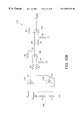
- FIG. 7A is a block diagram of an NMDA receptor channel circuit
- FIG. 7B is a plot of NMDA current in response to one pre-synaptic stimulus vs. time
- FIG. 8 is a block diagram of an LTP/LTD circuit
- FIG. 9A is a plot of calcium level vs. gain in non-NMDA receptors
- FIG. 9B is a block diagram of an LTP/LTD reversal circuit
- FIG. 10A is a block diagram of a bias circuit
- FIG. 10B is a schematic diagram of a scaling circuit.
- the biological neuron is the basic anatomical unit of a biological nervous system. It includes a cell body equipped with a tree of filamentary structures called dendrites. The dendrites are covered with structures called synapses. The synapses act as junctions through which are formed connections with other neurons. The synapses are the primary information processing elements in neural systems.
- the dendrites sum the synaptic inputs from other neurons, and the resulting currents are integrated on the membrane capacitance of the cell body until a signal threshold level is reached. At that point, an output neuron pulse, called the action potential, is generated and then propagates down the neuron's axon which is a relatively long structure used to transmit data.
- the end of the axon consists of a tree-shaped structure of synaptic contacts that connect to the dendrites of other neurons.
- the electrical activity in a neuron cell body occurs in the thin membrane that electrically separates the neurons interior from exterior fluid.
- An energy barrier is formed by the cell membrane that is so high that few ions are able to surmount it.
- metabolic pumps that actively expel sodium ions from the cytoplasm while importing potassium ions from the extra-cellular fluid. Typical concentrations of these ions inside and outside the cell are shown in Table I below.
- the concentration gradient that exists across the membrane is used to power electrical activity. Ions diffuse in/out, respectively, of the membrane while electrically drifting out/in.
- V r - kT q ⁇ ln ⁇ N in N ex , Equation ⁇ ⁇ 3
- the reverse potentials for the three ions in the membrane are shown in Table I.
- the sodium reverse potential may be thought of as a positive power supply rail and the potassium reverse potential as the negative rail.
- the electrical characteristics of the cell membrane may be represented as four parallel legs of a circuit. Three of the legs include a voltage source representing the reverse potentials of the ions, and with a conductance which represents the membrane permeability for that ion.
- the membrane capacitance is represented as the fourth leg and can be depicted as a lumped capacitor. For a given membrane voltage, the current through the membrane (i.e., the capacitor current) can be expressed as:
- I mem ( V memK ⁇ V K ) G K +( V Na ⁇ V mem ) G Na +( V Cl V mem ) G Cl Equation 4
- V 0 represents a so-called resting potential and is typically equal to a voltage of about ⁇ 85 millivolts (mV), although it can vary considerably.
- a neuron at rest is termed “polarized” to a negative potential and when the membrane potential becomes more positive the neuron is said to become depolarized.
- the delayed rectifier current, IKD along with the sodium current, generates the neuronal impulse.
- IKA A-current
- IAHP calcium dependent potassium current
- the activation and inactivation of the ion conductance in the membrane are themselves dependent on the membrane voltage and time. There is a sigmoidal relationship between the ion conductance and the membrane voltage. This creates a thresholding behavior that is responsible for the generation of the neuron pulse, or action potential. As the membrane becomes depolarized (in response to, for instance, an influx of synaptic current), there is a transient in the sodium conductance, followed by a delayed but prolonged increase in the potassium conductance. The currents through these conductance paths create the action potential.
- k′ is a physical parameter
- W/L is the ratio of the transistor channel width to channel length
- V GS is the gate-to-source voltage
- V t is the threshold voltage of the transistor
- ⁇ is the inverse of the Early voltage of the transistor
- V DS is the drain-to-source voltage.
- I DS k x ⁇ W L ⁇ ⁇ Vas nV r ⁇ ( 1 - ⁇ v as V r ) Equation ⁇ ⁇ 7
- V T is the thermal voltage, which is approximately 26 millivolts at room temperature.
- the drain current is essentially independent of the drain-to-source voltage.
- CMOS technology is used instead of bipolar technology because of the greater availability of CMOS processes.
- the current levels, and hence time scales, of subthreshold CMOS transistors match up fairly well with the actual biological levels.
- the nearly infinite resistance of the MOS gate is useful in many circuits. It should be noted, however, that in some applications bipolar or some technology other than CMOS technology may be preferred. Regardless of the particular technology used to fabricate physical devices or circuits which implement the functions and techniques of the neuron and synapse circuits described herein, the principles of the invention described herein still apply.
- a synapse circuit 20 includes a threshold detection circuit 22 having a first port 22 a coupled to a first port 20 a of the synapse circuit 20 and a second port 22 b coupled to a first port 24 c of a signal conversion and formatting circuit 24 .
- a second port 24 b of the signal conversion and formatting circuit 24 is coupled to a first port 26 a of a storage device 26 .
- the storage device 26 may include both an analog storage device for short term memory and a digital storage device for long term memory.
- a second port 26 b of the storage device 26 is coupled to a second port 20 b of the synapse circuit 20 .
- the synapse circuit 20 receives one or more signals at port 20 a.
- the threshold detection circuit 22 provides at port 22 b a response signal having a response signal level dependent upon the signal level of the signal received at port 22 a.
- the response signal is provided to signal conversion and formatting circuit 24 which converts the signal to a digital format and appropriately formats the signal for storage in the storage device 26 .
- synapse circuit 20 includes parallel signal paths 21 a - 21 c.
- a storage element 32 has a first port coupled to synapse port 20 a and a second port coupled to synapse port 20 b.
- the synapse circuit 20 also includes a relatively small leakage conductance and capacitance that represents the membrane capacitance of the spine head.
- the storage element 32 will be discussed in detail below in conjunction with FIGS. 4, 6 A and 7 . Suffice it here to say that the storage element 32 can include a short term memory portion which may be implemented as an analog circuit and a long term memory portion which may be implemented in a digital circuit.
- neurotransmitters include the amino acid glutamate.
- the transmitters bind to corresponding receptors on the post-synaptic membrane, causing ion channels to open up through these receptors.
- Glutamate binds to three types of receptors: n-methyl-D-aspartate (NMDA), quisqualate, and kainate.
- NMDA n-methyl-D-aspartate
- LTP and LTD are both mediated by the NMDA receptors, which carry primarily Ca 2+ currents.
- the other receptors termed the non-NMDA receptors, carry the rest of the synaptic current, consisting mainly of sodium ions Na + , with negligible calcium ion Ca 2+ content. These receptors are located on a spine head connected to the dendritic shaft. Thus, the total synaptic current consists of the sum of the NMDA and non-NMDA currents.
- the synapse circuit 20 By providing synapse circuit 20 with the parallel signal paths 21 a - 21 c, the synapse circuit 20 provides currents from the NMDA and non-NMDA circuits which are summed at terminal 20 b of the synapse circuit 20 .
- the current through the non-NMDA channels in response to a pre-synaptic stimulus is given by an alpha function:
- I non ( E non ⁇ V head ) ⁇ g p te t/p1 Equation 8
- the NMDA conductance is both ligand dependent, due to the binding of neurotransmitters released from the pre-synaptic neuron, and dependent on the spine head membrane voltage.
- the voltage dependence of the NMDA receptor arises from the fact that the receptors inhibited by Mg 2+ ions whose binding rate constant is dependent on the spine head membrane voltage. Near the resting membrane potential, the NMDA receptor channels are almost completely blocked by the Mg 2+ ions, and thus little current flows. As the spine head membrane becomes partially depolarized, the Mg 2+ ions become dislodged and more NMDA current flows.
- a non-NMDA receptor channel 34 also has a first port coupled to ports 20 a and 20 b of synapse circuit 20.
- the non-NMDA receptor channel 34 will be discussed in detail below in conjunction with FIG. 6 . Suffice it here to say that the non-NMDA receptor channel circuit 34 itself includes a number of channels which are set in particular conduction states. The number of channels and the particular conduction states of each of the channels determines the conductance values of the non-NMDA current.
- the non-NMDA current as well as the digital expression of memory aid in providing the circuit having a memory characteristic that in turn influences the rest of the neuron circuit.
- an NMDA receptor channel 36 has a first port coupled to ports 20 a and 20 b of synapse circuit 20 .
- NMDA receptor channel 34 will be discussed in detail below in conjunction with FIG. 7 . Suffice it here to say that the NMDA receptor channel circuit controls the long term memory effects because it responds to the neurotransmitters and the response is provided to the post-synaptic neuron. This provides a desired pairing effect.
- a calcium concentration measurement circuit 40 which measures the concentration of calcium ions Ca 2+ in the compartmentalized spine head includes a transconductance amplifier 42 having a first terminal 42 a coupled to receive a first signal V HEAD and a second terminal 42 b coupled to a reference voltage V REF .
- Amplifier 42 receives at a terminal 42 c a signal from an NMDA receptor channel circuit, such as the NMDA circuit 36 described above in conjunction with FIG. 2 .
- transconductance amplifier 42 is coupled to a first terminal 47 a of a diode connected NMOS current mirror 47 provided from a pair of transistors 48 , 50 having drain, source and gate electrodes 48 a - 48 c and 50 a - 50 c, respectively.
- Transistor 48 is coupled in a diode-connected configuration.
- the gate electrode 48 c of the transistor 48 is connected to the drain electrode 48 a.
- a second terminal 47 b of current mirror 47 is coupled to a first terminal 51 a of a second current mirror 51 which is here provided as a PMOS current mirror utilizing a pair of transistors 52 , 54 having drain, source and gate electrodes 52 a - 52 c and 54 a - 54 c, respectively.
- the current mirror 47 both “mirrors” and scales the input current I IN .
- the calcium concentration measurement circuit 40 measures the concentration of Ca 2+ ions in the compartmentalized spine head.
- the Ca 2+ ions are the impetus for the induction of LTP or LTD.
- the Ca 2+ ions enter the spine head primarily from the NMDA channel current, which mostly consists of Ca 2+ ions.
- the flow of Ca 2+ ions into the spine head is somewhat proportional to the NMDA current.
- a relatively accurate measure of the Ca 2+ concentration in the spine head is the measure of net charge over time that flows in the NMDA current.
- This charge is accumulated in the storage and buffer circuit 56 which provides a means for temporarily storing the charge.
- Storage and buffer circuit 56 may be implemented in a variety of techniques one of which will be described below in conjunction with FIG. 4 . Briefly, however, the storage and buffer circuit 56 stores the signal provided from the current mirror 51 .
- the storage and buffer circuit 56 is thus provided having at a terminal thereof a signal level (e.g. a signal voltage level) which is proportional to the signal provided from current mirror 51 .
- the concentration of Ca 2+ ions can be measured by accumulating a scaled copy of the NMDA current in the storage and buffer circuit 56 .
- the signal stored in the storage buffer circuit 56 thus represents the concentration of Ca 2+ ions.
- a threshold detection circuit 58 determines when the signal stored in storage and buffer circuit 56 reaches a predetermined signal level. When the stored signal voltage crosses certain voltage levels, the concentration of Ca 2+ ions in the spine head reaches certain levels thus triggering LTP or LTD. Consequently the signal voltage can be descriptively denoted V CA2+ . Thus, threshold detection circuit 58 indicates when the particular levels are reached.
- the storage and buffer circuit 56 includes a capacitor 60 having a first terminal coupled to storage and buffer circuit terminal 56 a and a second terminal coupled to a reference potential which here corresponds to ground. It should be noted that the second reference voltage could also correspond to a positive or negative voltage level.
- a transconductance amplifier 62 has an output terminal 62 a coupled to the first terminal of capacitor 60 and a first input terminal coupled to a reference voltage V RESET A bias voltage V LEAK is coupled to a bias terminal of the amplifier 62 .
- the capacitor 60 accumulates charge from current mirror 51 and thus is provided having voltage which is proportional to the charge. That is, the concentration of Ca 2+ ions can be measured by accumulating a scaled copy of the NMDA current onto the capacitor 60 .
- the voltage stored in the temporary storage buffer 56 thus represents the concentration of calcium ions Ca 2+ and is modeled as a short term memory by the capacitor 60 .
- the analog circuit is converted to a digital signal and can be stored in a digital storage device.
- the NMDA current is mirrored and scaled by the PMOS current mirror 51 . This current then is accumulated onto a capacitor having a first terminal coupled to the current mirror 51 and having a second terminal coupled to ground.
- the voltage on the capacitor can be expressed as
- V ca 2+ ( t ) 1 /C ⁇ 0 t NMDA ( t ) dt+V ca 2+ (0). Equation 12
- This provides for a leakage current having a time constant determined by the value of g m and thus is controllable by modifying the bias voltage V LEAK of the amplifier 62 and the capacitance of the capacitor 60 .
- the voltage V RESET determines the resting level of the capacitor voltage when no current is either flowing onto or leaking off of the capacitor 60 .
- Storage and buffer circuit 56 thus acts as a membrane capacitance and leakage conductance circuit 56 which represents cell membrane capacitance.
- capacitor 62 can be considered as being coupled between a “membrane” node and ground. The particular structure of the membrane node and ground is discussed below.
- the capacitor 62 is provided having a capacitance value typically of about 1 picofarad (pf).
- pf picofarad
- This leakage conductance is implemented using the transconductance amplifier 62 connected in a follower-integrator configuration, with the output voltage being the membrane voltage and the capacitor 60 corresponding to the membrane capacitance.
- the input voltage of the amplifier 62 should be the resting potential voltage. Since there is no leakage current when the membrane voltage is at the rest resting potential.
- the value of the leakage conductance is determined by the bias voltage of the transconductance amplifier, which determines its g m .
- the use of a transconductance amplifier yields a relatively close approximation of the linear conductance. If it is desirable to increase the range over which there is an approximately constant conductance, a wide input range transconductance amplifier can be used in place of the simple transconductance amplifier 62 .
- the leakage conductance can be implemented using a single transistor, having a gate voltage set to control the leakage current.
- This implementation does not emulate a true conductance however, as the current through the transistor does not vary, to first order, with its drain to source voltage. Nonetheless, since the leakage current is relatively small, the loss of accuracy comes with the benefit of a very simple and small implementation with a single transistor.
- a complete neuronal cell membrane circuit, including all of the synaptic circuits with the exception of the digital control circuitry, and the horizontal resistor circuit can be fabricated as a single integrated circuit.
- the digital control circuitry of the synaptic circuit can be implemented off chip using field programmable gate arrays.
- the threshold circuitry of the synapses includes four CMOS buffers, each with different switching thresholds.
- the scaling circuitry of the dendritic circuit can be implemented off-chip using discrete components and all bias voltages can be set on or off chip (i.e. on-chip or off-chip voltage references can be used).
- the capacitors were laid out using two layers of polysilicon that were available in the Orbit 2 micron process.
- Poly-poly capacitors have capacitances that are nearly independent of voltage, and thus can be operated over the full five volt voltage range.
- poly-diffusion capacitors are highly nonlinear with respect to voltage. It was not critical to lay out especially precise capacitors, as they generally served to form a time constant with a conductance whose value could be externally set. Furthermore, it is not necessary to match the operating characteristics of any capacitors.
- roughly 15 silicon neuron-synapse pairs can be integrated on one MOSIS tinychip (die area 2.2 mm. ⁇ 2.2 mm), with the Orbit 2.0 micron process, if the digital control circuit/memory is implemented off-chip, using FPGAs. If this circuitry is included on-chip, then roughly 10 neuron-synapse pairs can be integrated on the MOSIS tinychip.
- the density of an integrated circuit is roughly proportional to the square of the minimum feature size, a decrease in feature size to 0.25 or 0.35 micron (typical industrial process, then the number of silicon neuron-synapse pairs that can be integrated on a 2.2 mm. ⁇ 2.2 mm. die is increased by a factor of roughly 100.
- a threshold detection circuit 58 ′ which may, for example, be provided as the type used in the manner described above in conjunction with FIG. 3, includes a plurality of comparators 64 a - 64 c each of which has a first or negative terminal coupled to respective ones of reference voltages V REF1 ⁇ V REF3 .
- LTP or LTD may be triggered and threshold detection circuit 58 ′ determines when V Ca2+ has crossed certain voltage levels.
- the reference voltages are set through a resistive network 66 .
- a first terminal of network 66 is coupled to a first reference voltage VDD and second terminal of network 66 is coupled to a second reference voltage.
- the second reference voltage corresponds to ground but it should be noted that the second reference voltage could also correspond to a positive or negative voltage level.
- Coupled between the first and second terminals of resistive network 66 are a plurality of serially connected resistors 66 a, 66 b, 66 c which provide the reference voltages V REF1 ⁇ V REF3 .
- the reference voltages are thus generated by a resistive voltage divider 66 of the power supply voltage.
- This technique can be used when the comparators 64 a - 64 c draw little current at the input terminals which is often a reasonable assumption.
- This technique has the advantage of dissipating a relatively small amount of static power and the amount of power dissipated can be reduced by appropriately selecting the resistance values of the resistors 66 a - 66 c. Utilizing resistors having a relatively large resistance value require a relatively large amount of area on an integrated circuit while utilizing resistors having a relatively small resistance value require a relatively small amount of area on an integrated circuit.
- the reference voltages V REF1 ⁇ V REF3 could also be generated using other techniques. For example, the reference voltages could also be generated using band-gap or zener diodes.
- each comparator 64 a - 64 c compares the voltage signal V Ca2+ to the reference voltage and produces a digital 1 if the voltage level of the signal V Ca2+ is greater than the reference voltage level and a digital 0 if the voltage level of the signal V Ca2+ is less than the reference voltage signal level.
- the comparators 64 a - 64 c can be implemented via commercially available comparator circuits
- comparator circuits 64 a - 64 c can be implemented via a high gain differential voltage amplifier having an output coupled to a digital buffer.
- the amplifier saturates and the output voltage is very near one of the power supply rails.
- the digital buffer then assures that a good logic value is obtained, as well as buffering the amplifier output.
- a simple alternative to a complete comparator is to use only digital buffers (which is essentially an amplifier) to compare the voltage level of the signal V Ca 2+ to a reference voltage signal level.
- each digital buffer assumes the role of the comparator in while the voltage reference corresponds to a switching voltage of the digital buffer.
- the switching voltage of the digital buffer can be adjusted by appropriately changing the relative sizes of the p-channel and n-channel devices in the buffer.
- One drawback to this approach is that the reference voltages are subject to mismatch between transistors and are not adjustable once implemented.
- a non-NMDA receptor channel circuit 34 includes a transconductance amplifier 68 which provides an output current I out (t).
- the voltage range used in the non-NMDA receptor channel circuit 34 is the same as that used in the NMDA circuit to be described below in conjunction with FIG. 7 .
- the output current I out (t) is then scaled and mirrored by the p-channel current mirror 69 (which is required since the output voltage of the amplifier is near the supply voltage) and provided to a control circuit 70 provided from a set of conductance transistors 70 a - 70 N.
- the conductance transistors 70 a - 70 N form what is essentially an n-channel current mirror with multiple legs, in the form of a simple digital-to-analog converter.
- the legs of the current mirror contain control transistors 70 a - 70 N that turn on or off each leg of the conductance.
- the binary control inputs can be used to regulate the peak amount of non-NMDA current that flows into the spine head.
- Each set of control input values corresponds to the different conductance levels associated with LTP and LTD.
- each succeeding leg of the D/A converter control circuit 70 is scaled by a factor of two, so that the conductance changes are binary, corresponding to the control values. If the peak non-NMDA current is plotted as a function of spine head voltage (e.g. for a nominal set of control inputs), ideally, the slope of the curve should be constant, as the non-NMDA conductance is not a function of the spine had voltage. Nonetheless, the slope, and hence, conductance, should remain relatively constant over the range of spine head voltages.
- the conductance changes associated with LTP and LTD occur smoothly in value and time.
- the conductance changes in discrete steps in this particular embodiment only two control signals C 0 , C 1 are shown, it should be appreciated that circuitry to accommodate more control signals could be added to increase the number of different conductance levels. As the number of control signals increase, the size of the discrete steps in conductance values decrease, and thus the circuit more closely approximates the smoothness of real neurons. Since more area on an integrated circuit is required to accommodate the control circuitry, a trade-off must thus be made between silicon area to accommodate the desired number of transistors and desired precision and smoothness of the conductance values.
- the current through the legs of the control circuit 70 charges a capacitor 71 . When charged, the capacitor 71 holds a voltage V head at a node 72 .
- control signals C 0 , C 1 which are digital in nature, are thus determined in part by the threshold detection circuitry in the manner discussed above in conjunction with FIGS. 3 and 5.
- the output of threshold signals TH 0 , TH 1 , and TH 2 of the detection circuit 58 ′ are manipulated digitally, using information about the current conductance value, to produce the control inputs for the non-NMDA circuit 34 .
- the threshold signal levels TH 0 -TH 2 are provided to a digital control circuit 75 via digital inverters 74 a - 74 c rather than via the comparator-resistive network approach described above in conjunction with FIG. 5 .
- the digital inverter approach results in a circuit which utilizes less power and can be implemented in less area on an integrated circuit than the comparator approach.
- each of the inverters 74 a - 74 c is coupled to a reference voltage V CA2+ at a node 73 and to a first terminal of a capacitor 76 .
- the reference voltage V CA2+ is provided by the NMDA receptor channel circuit 36 described below in conjunction with FIG. 7.
- a second terminal of the capacitor 76 is coupled to a second reference potential.
- the second reference voltage corresponds to ground but it should be noted that the second reference voltage could also correspond to a positive or negative voltage level.
- the digital control circuit 75 receives the signals TH 0 , TH 1 , and TH 2 from the detection circuit 58 ′,processes the signals TH 0 , TH 1 , and TH 2 in a manner to be described below in conjunction with FIG. 8 and provides the control signals C 0 , C 1 to the control terminals of the conductance transistor control circuit 70 .
- the induction of LTP is characterized by a prolonged increase in the conductance of the non-NMDA receptor channel, while the induction of LTD is characterized by the decrease in conductance of the non-NMDA receptor channel.
- This is achieved in the conductance transistor control circuit 70 by the control signals C 0 , C 1 which bias the respective transistors 70 a - 70 N into conduction or non-conduction states.
- the digital control circuit 75 determines the signal levels of the control signals C 0 , C 1 which turn on or off the conductance transistors 70 a - 70 N and thus control current flow through the circuit legs provided by the transistors 70 a - 70 N.
- LTP and LTD are initiated when the concentration of Ca 2+ ions in the spine head reach certain levels.
- the calcium concentration measurement circuit and threshold detection circuits discussed above in conjunction with FIGS. 3-5 perform the functions of measuring the concentration of Ca 2+ ions in the spine head and determining when it has reached certain levels.
- the outputs of the threshold detection circuit 58 (FIG. 3) and 58 ′ (FIG. 4) are digital values. These digital signals are then used to determine the value of the control inputs, C 1 and C 0 , in FIG. 6 .
- a cascaded follower-integrator circuit 77 is coupled to amplifier 68 and will be discussed in detail below in conjunction with FIG. 6 B. Suffice it here to say that the follower-integrator circuit 77 receives a pre-synaptic input signal and provides an output signal which approximates the function: ⁇ g p t ⁇ t/ ⁇ p .
- a cascaded follower-integrator circuit 77 ′ which acts as an RC delay line and provides a time varying current circuit function is shown.
- the NMDA and non-NMDA channels open in response to a pre-synaptic stimulus of the action potential of another neuron.
- current flows according to Equations 3 and 4.
- the time dependence for each of these equations can be represented as an alpha function.
- These can be treated as the impulse responses of the spine head channels to a pre-synaptic stimulus.
- ⁇ 1 may be provided having the same value as ⁇ 2 . It should be appreciated, however, that in other embodiments ⁇ 1 may be provided having a value which is different than ⁇ 2 .
- the current I(t) can be implemented in a number of ways. As shown in FIG. 6B, one technique to approximate the alpha function behavior is to apply a pre-synaptic input signal to a pair of cascaded follower integrators 78 , 80 .
- the output of the second follower integrator 80 is connected to a control electrode of a transistor 84 .
- the transistor 84 is, in this particular example, implemented as an NMOS transistor 84 and the control electrode corresponds to the gate electrode of the transistor 84 .
- the transfer function from input to the voltage on the gate electrode of the transistor 84 is given by:
- V GS /V in 1/((1+ ⁇ 1 s )(1+ ⁇ 2 s )) Equation 15
- the gate voltage on the NMOS transistor 84 will change incrementally like an alpha function. If this change in gate voltage is small, the incremental change in current through the transistor will be approximately
- the pre-synaptic input is, however, the neuron impulse, or action potential, of another neuron, as discussed above. If this action potential were buffered with a digital buffer, the output would be short, essentially constant valued pulse as desired.
- One drawback to the present embodiment is that even when there is no pre-synaptic input, there is current that flows through the NMOS transistor. This arises from the fact there is a non-zero voltage on the capacitors 81 , 82 . This is because the output voltage of a simple transconductance amplifier in the follower configuration does not follow the input voltage when the input is zero. To minimize this problem, the simple transconductance amplifiers 78 . 80 can be replaced by wide output range amplifiers, which are capable of providing output voltages closer to ground. Even in this case, there will be some current, albeit smaller, even when the input voltage is zero. This small amount of current can either be tolerated, or can be compensated by providing for an optional leakage transistor circuit 86 . The bias voltage for the leakage can be determined by sensing circuitry or it may be externally set.
- the time varying current I(t) function can also be provided by using a current mirror 77 ′′ similar to that used for the non-NMDA conductance.
- the circuit 77 ′′ includes a plurality of transistors 77 a ′′- 77 N′′ each of which receives a respective one of control signals C 0 -C N .
- the value of the control signals C 0 -C N determines which transistors are biased into conduction and non-conduction states and thus determines when each leg of the current mirror 69 ′ conducts.
- the size of the transistor in each successive leg 77 a ′′- 77 N′′ is scaled by two to provide a binary implementation.
- the control signals C 0 -C N inputs can then be controlled so that the total output current approximates an alpha function.
- the accuracy of this implementation is improved by adding more legs in the current mirror 77 ′′.
- One drawback of this circuit is the requirement of digital control logic to determine the control inputs.
- this implementation can potentially provide a very accurate approximation of an alpha function current, and no current flows when there is no input, unlike the use of follower integrators discussed above in conjunction with FIG. 6 B.
- the current I(t) can simply be provided as a constant-value pulse of current, which could also be implemented using the circuit 69 ′ but with only one control input. It should be noted, however, that such an implementation would be a deviation from the concept of using life-like principles in design of the neuron circuits.
- FIG. 6D a plot of NMDA current as a function of time following a single pre-synaptic stimulus is shown. As expected, the NMDA current approximates an alpha function.
- an NMDA receptor channel circuit 36 is shown. As noted above in Equation 9, the conductance of the NMDA channel 36 not only varies with time, but also depends upon the spine head membrane voltage.
- the NMDA circuit 36 includes a differential pair circuit 88 .
- I 2 k x ⁇ W 2 L 2 ⁇ ⁇ ( v 1 - v ) nVr Equation ⁇ ⁇ 18
- I 1 corresponds to I 1diffpair and I 2 corresponds to I 2diffpair .
- I(t) NMDA the current I(t) NMDA through the bias transistor as shown.
- Coupled to the differential pair circuit 88 is a cascaded follower integrator circuit 90 provided from a pair of differential amplifiers 90 a, 90 b, a pair of capacitors C 1 , C 2 and a transistor 90 c coupled as shown.
- the cascaded follower integrator circuit 90 can be considered as voltage controlled resistors connected to capacitors to function as an RC delay line.
- the cascaded follower integrator circuit 90 receives a pre-synaptic input signal at a positive input terminal thereof.
- the pre-synaptic input signal may be digitized to an impulse signal.
- the cascaded follower integrator circuit 90 operates in a manner similar to that described above in conjunction with FIG. 6B to generate an alpha function from an action potential of another neuron.
- the alpha function provides a response described by a 1 exp[ ⁇ t/ ⁇ 1 ] ⁇ a 2 exp[ ⁇ t/ ⁇ 2 ] where a 1 and a 2 are empirically selected values used to reflect that integrators in electronic circuits can be described using functions which include time and amplitude. It should be noted that, generally, an alpha function includes a single exponential with time modulation. It should thus be appreciated the alpha function described above using two terms may equivalently be expressed by a single term function or that other multiple term representations may also be used.
- I diffpair I ⁇ ( t ) ⁇ 1 1 + Z ⁇ ⁇ ⁇ V Ref - V Head nV T Equation ⁇ ⁇ 22
- Z is the ratio of the sizes of the transistors in the two legs of the differential pair.
- I diffpair then serves as the bias current for a transconductance amplifier 91 .
- current mirror circuits 93 , 94 provides a scaled down copy of the NMDA current I out-amp that charges/discharges the capacitor 71 .
- the capacitor 71 holds a voltage V HEAD at the node 72 .
- This technique represents a model in which a the flow of Ca2+ ions into the spine head is approximately proportional to the NMDA current.
- the current mirror 93 provides to a transconductance amplifier circuit 97 a current signal I Ca2+ which corresponds to a scaled down version of the current signal I out-amp .
- the transconductance amplifier circuit 97 acts as a voltage controlled resistor having a resistance value set by the reference voltage V LEAK .
- the capacitor 76 holds at a node 73 a voltage level V CA2+ which is proportional the Ca 2+ ions within the spine head. The charge will dissipate from or “leak off of” node 99 until the voltage V CA2+ falls to a value equal to V REST . This is the mechanism by which transient pulses in the CA 2+ can return to nominal signal levels.
- the spine head voltage varies between ⁇ 80 mV and 0 mV[6].
- the biological 0 V is again chosen to be 2.5 V.
- x is the ratio of the electronic implementation voltage to the actual biological voltage.
- n is the ratio of the electronic implementation voltage to the actual biological voltage.
- x should be approximately 2.
- the voltages are related according to:
- V electronic 2 V biological +2.5 V Equation 25
- the spine head voltage in the electronic implementation, will vary from approximately 2.34 V to 2.5 V. This implies that the voltage signal V Ref in FIG. 7A should equal about 2.5 V. Also, since the differential input of the transconductance amplifier is potentially up to 160 mV, greater than the linear range of the simple transconductance amplifier, it is best to replace the simple transconductance amplifier with one with a wide input range. having a linear range of nearly 200 mV.
- FIG. 7B a plot of non-NMDA current as a function of time following a single pre-synaptic stimulus is shown. As expected, the non-NMDA current approximates an alpha function with the peak value occurring at a time which is earlier than the time at which the peak value of the NMDA current occurs (FIG. 6 D).
- a digital control circuit 59 for induction of LTP and LTD receives from a threshold circuit the threshold signals TH 0 -TH 2 at respective ones of input ports 59 a - 59 c and provides control signals C 0 , C 1 having appropriate signal levels at output ports 59 d, 59 e.
- the threshold signals may be provided in any appropriate manner.
- the threshold signals TH 0 -TH 2 may be provided from any of the threshold circuits described above including those described in conjunction with FIGS. 1, 3 , 5 and 6 .
- the induction of LTP is characterized by a prolonged increase in the conductance of the non-NMDA receptor channel
- the induction of LTD is characterized by the decrease in conductance of the non-NMDA receptor channel.
- This is achieved in the non-NMDA channel circuit 34 (FIG. 6) by the control signals C 0 , C 1 turning on or off the legs of the conductance transistors 72 (FIG. 6 ).
- the digital control circuit 59 receives the threshold signals TH 0 -TH 2 and determines the value of the control signals C 0 , C 1 and thus determines the induction of LTP and LTD.
- LTP and LTD are initiated when the concentration of Ca 2+ ions in the spine head reach certain levels.
- the circuitry discussed in calcium concentration measurement circuit 40 (FIG. 3) measures the concentration of Ca 2+ ions in the spine head and then determines when it has reached certain levels.
- the threshold circuit provides digital values signals which are used to determine the value of the control inputs, C 1 and C 0 , in FIG. 6A
- the manner in which this is accomplished depends upon the type of algorithm for LTP/LTD that is being implemented.
- the truth table for this technique is shown in Table II.
- the signals Th 0 -Th 2 correspond to the output signals of the threshold detection circuitry described above in conjunction with FIGS. 1-7C.
- the signals Th 0 -Th 2 correspond to the output signals of the threshold detection circuitry described above in conjunction with FIGS. 1-7C.
- control signals C 1 , C 0 are not updated continuously in time, but rather at discrete intervals.
- the duration of the time interval is the length of time for which LTP or LTD is in effect. This is accomplished via the digital circuits 100 included in the digital control circuit 59 .
- the digital circuits 100 implemented the digital logic expressed by Equations 26, 27. It should be appreciated of course that any digital logic circuit capable of implementing the logic set forth in Equations 26, 27 could also be used.
- Register circuit 102 provides control signals C 0 , C 1 at the output ports 59 d, 59 e of the digital control circuit 59 .
- the period of the clock signal for the register circuit 102 determines how long LTP or LTD is in effect.
- FIG. 9A a plot illustrating the dependence of the change in conductance on the calcium concentration is shown.
- LTP and LTD can reverse each other. In other words, the current conductance state depends upon the previous conductance state. If the non-NMDA conductance is initially in a potentiated state, and the calcium concentration dictates that LTD should be initiated, then the next conductance state would be a more nominal level, as opposed to fully depressed. With this technique, it is the change in conductance, rather than the actual conductance level, that is affected by the concentration of calcium ions and it is this dependence which is shown qualitatively in FIG. 9 .
- G[n] represents the current conductance state
- FIG. 9B is a block diagram of a circuit which implements the threshold logic of the LTP/LTD reversal algorithm.
- the four threshold outputs Th 3 -Th 0 of FIG. 9B can be represented by a two's complement three-bit number expressed as DG 2 -DG 0 .
- the truth table for the signals DG 2 -DG 0 is shown in Table III.
- Th3 Th2 Th1 Th0 DG2 DG1 DG0 Potentiation 0 0 0 0 0 0 0 0 0 0 0 0 1 1 1 0 ⁇ 2 0 0 1 1 1 0 1 ⁇ 1 0 1 1 1 0 0 1 +1 1 1 1 1 0 1 0 +2
- the signals DG 2 -DG 0 represents a change in C 1 -C 0 ranging from ⁇ 2 to +2. From this truth table, logic expressions for DG 2 -DG 0 can be derived in terms of Th 3 -Th 0 and expressed as:
- the reversal circuit 59 ′ implements the LTP/LTD reversal algorithm.
- Reversal circuit 59 ′ includes as threshold logic circuit 110 which receives threshold signals TH 0 -TH 3 and provides digital output signals DG 0 -DG 2 .
- the signals DG 0 -DG 2 are fed to and FSM logic circuit 112 .
- the output of the FSM logic circuit 112 is coupled to a register 114 .
- the output of register 114 are the current conductance state control signals C 1 and C 0 .
- the current conductance state control signals C 1 and C 0 coupled back to the input to the FSM logic circuit 112 .
- the output signals CN 0 -CN 1 of the FSM logic circuit 112 correspond to the next control signals, CN 1 and CN 0 which are fed into the register circuit 114 which is clocked by a signal having a period which determines the length of LTP or LTD.
- CN 1 C 1 ⁇ overscore ( DG 2 ) ⁇ overscore ( DG 1 ) ⁇ + C 0 ⁇ overscore ( DG 2 ) ⁇ DG 0 + DG
- CN 0 ⁇ overscore ( DG 2 ) ⁇ C 1 ⁇ C 0 + ⁇ overscore ( C 0 ) ⁇ overscore ( DG 2 ) ⁇ DG 0 + C 0 ⁇
- FIG. 10 a bias circuit which produces bias voltages at the gates of the pass transistors of the horizontal circuit.
- the bias circuitry must adjust the gate voltage such that V q defined in Equation 34 is held constant even when the node voltages V 1 and V 2 change.
- FIG. 10A illustrates this function for the signal voltage VG 1 .
- An identical circuit with V 2 as the input generates the signal voltage VG 2 .
- the horizontal resistor bias circuit is essentially a transconductance amplifier connected in the follower configuration, with the addition of the diode connected transistor Md.
- the gate voltage of transistor M 2 follows the voltage V 1 .
- the voltage VG 1 is thus equal to the voltage V 1 plus an offset equal to the voltage across the diode connected transistor Md.
- This offset is the voltage required to maintain the current through transistor Md, which is half of the bias current Ib.
- This offset is in fact equal to V 9 .
- Equation 35 relates V q to the bias current I b . That is, setting the gate voltage of the bias transistor Mb determines the signal voltage V q , independent of V 1 or V 2 . This in turn determines the resistance of the horizontal resistor connection.
- An expression for the effective resistance of the connection that is solely dependent on I b and the thermal voltage may thus be written as:
- the effective resistance of the horizontal resistor connection can vary over many orders of magnitude. In operation, as the bias voltage increases, more current flows, corresponding to a decrease in effective resistance.
- This 100 millivolt linear range of the horizontal resistor configuration may not be enough in certain applications.
- multiple horizontal resistor circuits can be placed in series to increase the range over which the circuits behave like a constant resistance.
- the horizontal resistor circuit is a practical and flexible way to implement the dendritic resistance of then neuron.
- a single connection may suffice, although multiple circuits may be cascaded to increase the linear resistive range.
- this may not be necessary since the spine head voltage and the neuron cell voltage do not differ much in voltage, except at the instance of an action potential, which is of relative short duration.
- the saturation of the resistor current at this time may be within an acceptable tolerance range.
- a scaling circuit 130 includes a first operational amplifier (op-amp) 132 connected in the unity buffer configuration and having a first input signal V mem coupled to the positive input of op-amp 132 and having a second input voltage V HEADOUT set equal to the output voltage V 1 coupled to the negative input terminal of op-amp 132 .
- the buffer configuration is used so that the scaling circuit 130 does not load the other circuitry and draw current from it.
- a second op-amp 134 is also connected in the unity buffer configuration. Its input voltage is one half of the power supply voltage, created by the resistive divider network 136 provided from resistors R 1 .
- the op-amp 134 generates a reference voltage V ref at the output port thereof When the supply voltage Vsupply is set equal to 5 volt, for example, the signal voltage V ref equals 2.5 volts.
- the op-amps 138 , 140 are each connected in the differential amplifier configuration.
- the output voltage of op-amp 138 is provided as:
- amplifiers 132 - 138 are here shown as operational amplifiers, any amplifier having a relatively large gain and a relatively small output resistance (e.g. a MOS amplifier) can also be used. It should also be appreciated that it may be desirable to fabricate the scaling circuit 130 as a portion of an integrated circuit. In some applications, however, the scaling circuit may be implemented using discrete, off-chip, components.
- the dendritic circuit connects the neuron membrane circuits to the spine head or synaptic circuits discussed above.
- these two different groups of circuits operate over different voltages ranges. Both voltage ranges possess the same ground, or reference, voltage, equal to 2.5 volts.
- the neuron membrane circuits operate over a range that is five times as big as the range for the spine head circuits. Recall that this difference in voltage scale resulted from the different exponential dependence on voltage that the two different types of circuits exhibited. Since the neuron membrane circuits are connected to the spine head circuits through the dendritic resistance, this difference in voltage scales is a problem.
- the spine head node in the circuits in FIG. 5 are connected to the gates and drains of the transistors and that such connections to the transistor gates are essentially the inputs of the circuit, while the connections at the transistors drain serve as the outputs. Consequently, these output signals essentially behave like current sources. That is; the output current is negligibly affected by the head voltage at these drain connections.
- the voltage scale does not really matter and can therefore be on the same scale as neuron cell membrane circuit.
- FIGS. 6A and 7A show the NMDA and non-NMDA circuits with the input spine head nodes (HEADIN) and the output nodes (HEADOUT).
- the HEADOUT node can be connected to one end on the horizontal resistor network, with the other end connected to the neuron cell membrane.
- the HEADIN voltage must be scaled version of the HEADOUT voltage to achieve the necessary voltage scale.
- V Ref is equal to 2.5 volts. This behavior can be implemented by using the scaling circuit 130 circuit 130 .
- circuits can be designed to generate many of the voltage references that are needed. While some of these references are intended to be variable, in certain cases it may be desired that they are fixed. Also, circuits can be developed to emulate different types of synapses, and different learning techniques, including first in building an artificial neural network that emulate the analog behavior or real neurons.
Priority Applications (4)
| Application Number | Priority Date | Filing Date | Title |
|---|---|---|---|
| US09/332,790 US6507828B1 (en) | 1998-06-19 | 1999-06-14 | Neuron circuit and related techniques |
| US09/611,137 US6687686B1 (en) | 1998-06-19 | 2000-07-06 | Hebbian synapse circuit |
| US10/751,396 US20040139040A1 (en) | 1998-06-19 | 2004-01-05 | Hebbian synapse circuit |
| US11/059,168 US7047225B2 (en) | 1998-06-19 | 2005-02-16 | Hebbian synapse circuit |
Applications Claiming Priority (2)
| Application Number | Priority Date | Filing Date | Title |
|---|---|---|---|
| US9006998P | 1998-06-19 | 1998-06-19 | |
| US09/332,790 US6507828B1 (en) | 1998-06-19 | 1999-06-14 | Neuron circuit and related techniques |
Related Child Applications (1)
| Application Number | Title | Priority Date | Filing Date |
|---|---|---|---|
| US09/611,137 Continuation-In-Part US6687686B1 (en) | 1998-06-19 | 2000-07-06 | Hebbian synapse circuit |
Publications (1)
| Publication Number | Publication Date |
|---|---|
| US6507828B1 true US6507828B1 (en) | 2003-01-14 |
Family
ID=26781825
Family Applications (4)
| Application Number | Title | Priority Date | Filing Date |
|---|---|---|---|
| US09/332,790 Expired - Fee Related US6507828B1 (en) | 1998-06-19 | 1999-06-14 | Neuron circuit and related techniques |
| US09/611,137 Expired - Fee Related US6687686B1 (en) | 1998-06-19 | 2000-07-06 | Hebbian synapse circuit |
| US10/751,396 Abandoned US20040139040A1 (en) | 1998-06-19 | 2004-01-05 | Hebbian synapse circuit |
| US11/059,168 Expired - Fee Related US7047225B2 (en) | 1998-06-19 | 2005-02-16 | Hebbian synapse circuit |
Family Applications After (3)
| Application Number | Title | Priority Date | Filing Date |
|---|---|---|---|
| US09/611,137 Expired - Fee Related US6687686B1 (en) | 1998-06-19 | 2000-07-06 | Hebbian synapse circuit |
| US10/751,396 Abandoned US20040139040A1 (en) | 1998-06-19 | 2004-01-05 | Hebbian synapse circuit |
| US11/059,168 Expired - Fee Related US7047225B2 (en) | 1998-06-19 | 2005-02-16 | Hebbian synapse circuit |
Country Status (1)
| Country | Link |
|---|---|
| US (4) | US6507828B1 (US06687686-20040203-M00023.png) |
Cited By (15)
| Publication number | Priority date | Publication date | Assignee | Title |
|---|---|---|---|---|
| US6687686B1 (en) * | 1998-06-19 | 2004-02-03 | Massachusetts Institute Of Technology | Hebbian synapse circuit |
| US6763340B1 (en) * | 2000-09-22 | 2004-07-13 | The United States Of America As Represented By The Secretary Of The Air Force | Microelectromechanical system artificial neural network device |
| US7580907B1 (en) * | 2004-01-14 | 2009-08-25 | Evolved Machines, Inc. | Invariant object recognition |
| US20090219889A1 (en) * | 2002-04-29 | 2009-09-03 | Uwe Schwarz | Method and Apparatus for Utilizing Synchronization Information |
| US7814038B1 (en) * | 2007-12-06 | 2010-10-12 | Dominic John Repici | Feedback-tolerant method and device producing weight-adjustment factors for pre-synaptic neurons in artificial neural networks |
| US20110106742A1 (en) * | 2009-11-05 | 2011-05-05 | Pino Robinson E | Neuromorphic computer |
| US20110137843A1 (en) * | 2008-08-28 | 2011-06-09 | Massachusetts Institute Of Technology | Circuits and Methods Representative of Spike Timing Dependent Plasticity of Neurons |
| US20110140736A1 (en) * | 2009-12-14 | 2011-06-16 | University Of Hawaii | Systems and methods for brain-like information processing |
| US20120213013A1 (en) * | 2009-08-12 | 2012-08-23 | Taiwan Semiconductor Manufacturing Company, Ltd. | Memory building blocks and memory design using automatic design tools |
| EP2811453A1 (en) * | 2012-01-27 | 2014-12-10 | Korea Advanced Institute Of Science And Technology | Visual cortical circuit apparatus, visual cortical imitation system and object search system using visual cortical circuit apparatus |
| CN106137193A (zh) * | 2016-07-29 | 2016-11-23 | 普罗朗生物技术(无锡)有限公司 | 人体生物电导多值模拟器 |
| US20170324239A1 (en) * | 2016-05-09 | 2017-11-09 | Realtek Semiconductor Corporation | Electro-static discharge protection circuit |
| US11157803B2 (en) * | 2017-03-31 | 2021-10-26 | Sk Hynix Inc | Neuromorphic device including a synapse having a variable resistor and a transistor connected in parallel with each other |
| US11182669B2 (en) * | 2017-03-03 | 2021-11-23 | Denso Corporation | Neural network circuit |
| US20230367725A1 (en) * | 2022-05-12 | 2023-11-16 | Intel Corporation | Provisioning a reference voltage based on an evaluation of a pseudo-precision resistor of an ic die |
Families Citing this family (29)
| Publication number | Priority date | Publication date | Assignee | Title |
|---|---|---|---|---|
| US7089218B1 (en) * | 2004-01-06 | 2006-08-08 | Neuric Technologies, Llc | Method for inclusion of psychological temperament in an electronic emulation of the human brain |
| US7925492B2 (en) | 2004-01-06 | 2011-04-12 | Neuric Technologies, L.L.C. | Method for determining relationships through use of an ordered list between processing nodes in an emulated human brain |
| GB0101759D0 (en) * | 2001-01-23 | 2001-03-07 | Toumaz Technology Ltd | Circuit |
| US9269043B2 (en) | 2002-03-12 | 2016-02-23 | Knowm Tech, Llc | Memristive neural processor utilizing anti-hebbian and hebbian technology |
| US7412428B2 (en) * | 2002-03-12 | 2008-08-12 | Knowmtech, Llc. | Application of hebbian and anti-hebbian learning to nanotechnology-based physical neural networks |
| US6809558B1 (en) * | 2003-05-29 | 2004-10-26 | Winbond Electronics Corporation | Push-pull output neuron circuit |
| US7519452B2 (en) * | 2004-04-15 | 2009-04-14 | Neurosciences Research Foundation, Inc. | Mobile brain-based device for use in a real world environment |
| US7467115B2 (en) * | 2004-07-15 | 2008-12-16 | Neurosciences Research Foundation, Inc. | Mobile brain-based device having a simulated nervous system based on the hippocampus |
| US8473449B2 (en) * | 2005-01-06 | 2013-06-25 | Neuric Technologies, Llc | Process of dialogue and discussion |
| FR2919410B1 (fr) * | 2007-07-27 | 2009-11-13 | Univ Paris Sud | Synapse nano-electrique et procede d'apprentissage d'une telle synapse |
| WO2010008624A2 (en) * | 2008-03-25 | 2010-01-21 | Nantero, Inc. | Carbon nanotube-based neural networks and methods of making and using same |
| US20090292661A1 (en) * | 2008-05-21 | 2009-11-26 | Haas Alfred M | Compact Circuits and Adaptation Techniques for Implementing Adaptive Neurons and Synapses with Spike Timing Dependent Plasticity (STDP). |
| US8285523B2 (en) * | 2009-02-17 | 2012-10-09 | Massachusetts Institute Of Technology | Electronic system for modeling chemical reactions and biochemical processes |
| EP2259215B1 (en) * | 2009-06-04 | 2016-08-10 | Honda Research Institute Europe GmbH | Method and structure for a neural associative memory based on optimal Bayesian learning |
| US8653867B1 (en) * | 2009-07-16 | 2014-02-18 | Massachusetts Institute Of Technology | Pulse modulated neural integrator circuit and associated phase locked loop |
| US9092736B2 (en) * | 2010-07-07 | 2015-07-28 | Qualcomm Incorporated | Communication and synapse training method and hardware for biologically inspired networks |
| US9129220B2 (en) | 2010-07-07 | 2015-09-08 | Qualcomm Incorporated | Methods and systems for digital neural processing with discrete-level synapes and probabilistic STDP |
| US9269042B2 (en) | 2010-09-30 | 2016-02-23 | International Business Machines Corporation | Producing spike-timing dependent plasticity in a neuromorphic network utilizing phase change synaptic devices |
| US20120084240A1 (en) * | 2010-09-30 | 2012-04-05 | International Business Machines Corporation | Phase change memory synaptronic circuit for spiking computation, association and recall |
| US8959040B1 (en) * | 2012-03-08 | 2015-02-17 | Hrl Laboratories, Llc | Spike timing dependent plasticity apparatus, system and method |
| US9477926B2 (en) | 2012-11-20 | 2016-10-25 | Qualcomm Incorporated | Piecewise linear neuron modeling |
| WO2014151443A1 (en) * | 2013-03-15 | 2014-09-25 | Adc Telecommunications, Inc. | Ferrules for fiber optic connectors |
| US9418333B2 (en) | 2013-06-10 | 2016-08-16 | Samsung Electronics Co., Ltd. | Synapse array, pulse shaper circuit and neuromorphic system |
| US11501143B2 (en) | 2013-10-11 | 2022-11-15 | Hrl Laboratories, Llc | Scalable integrated circuit with synaptic electronics and CMOS integrated memristors |
| US10169701B2 (en) * | 2015-05-26 | 2019-01-01 | International Business Machines Corporation | Neuron peripheral circuits for neuromorphic synaptic memory array based on neuron models |
| US10671911B2 (en) * | 2016-02-19 | 2020-06-02 | International Business Machines Corporation | Current mirror scheme for an integrating neuron circuit |
| KR20180070196A (ko) * | 2016-12-16 | 2018-06-26 | 에스케이하이닉스 주식회사 | 뉴로모픽 장치의 정보 인식 장치 및 방법 |
| GB201901982D0 (en) * | 2019-02-13 | 2019-04-03 | Univ Oxford Innovation Ltd | Emulation of electrophysiological signals derived by stimulation of a body |
| US20210133677A1 (en) * | 2019-10-31 | 2021-05-06 | Walmart Apollo, Llc | Apparatus and methods for determining delivery routes and times based on generated machine learning models |
Citations (1)
| Publication number | Priority date | Publication date | Assignee | Title |
|---|---|---|---|---|
| US5592589A (en) * | 1992-07-08 | 1997-01-07 | Massachusetts Institute Of Technology | Tree-like perceptron and a method for parallel distributed training of such perceptrons |
Family Cites Families (6)
| Publication number | Priority date | Publication date | Assignee | Title |
|---|---|---|---|---|
| US3585615A (en) * | 1968-06-29 | 1971-06-15 | Nippon Electric Co | Analog memory apparatus |
| CA1023470A (en) * | 1974-11-12 | 1977-12-27 | Robert S. Meijer | Analog memory system |
| IT1237269B (it) * | 1989-11-15 | 1993-05-27 | Rete neurale con capacita' di apprendimento per il trattamento di informazioni, e procedimento per il trattamento di informazioni con l'impiego di tale rete. | |
| US5172204A (en) * | 1991-03-27 | 1992-12-15 | International Business Machines Corp. | Artificial ionic synapse |
| US5315162A (en) * | 1991-10-04 | 1994-05-24 | Hughes Aircraft Company | Electrochemical synapses for artificial neural networks |
| US6507828B1 (en) * | 1998-06-19 | 2003-01-14 | Jason Leonard | Neuron circuit and related techniques |
-
1999
- 1999-06-14 US US09/332,790 patent/US6507828B1/en not_active Expired - Fee Related
-
2000
- 2000-07-06 US US09/611,137 patent/US6687686B1/en not_active Expired - Fee Related
-
2004
- 2004-01-05 US US10/751,396 patent/US20040139040A1/en not_active Abandoned
-
2005
- 2005-02-16 US US11/059,168 patent/US7047225B2/en not_active Expired - Fee Related
Patent Citations (1)
| Publication number | Priority date | Publication date | Assignee | Title |
|---|---|---|---|---|
| US5592589A (en) * | 1992-07-08 | 1997-01-07 | Massachusetts Institute Of Technology | Tree-like perceptron and a method for parallel distributed training of such perceptrons |
Cited By (27)
| Publication number | Priority date | Publication date | Assignee | Title |
|---|---|---|---|---|
| US6687686B1 (en) * | 1998-06-19 | 2004-02-03 | Massachusetts Institute Of Technology | Hebbian synapse circuit |
| US20040139040A1 (en) * | 1998-06-19 | 2004-07-15 | Louis Nervegna | Hebbian synapse circuit |
| US20050137993A1 (en) * | 1998-06-19 | 2005-06-23 | Massachusetts Institute Of Technology | Hebbian synapse circuit |
| US7047225B2 (en) | 1998-06-19 | 2006-05-16 | Massachusetts Institute Of Technology | Hebbian synapse circuit |
| US6763340B1 (en) * | 2000-09-22 | 2004-07-13 | The United States Of America As Represented By The Secretary Of The Air Force | Microelectromechanical system artificial neural network device |
| US20090219889A1 (en) * | 2002-04-29 | 2009-09-03 | Uwe Schwarz | Method and Apparatus for Utilizing Synchronization Information |
| US8447712B1 (en) | 2004-01-14 | 2013-05-21 | Evolved Machines, Inc. | Invariant object recognition |
| US7580907B1 (en) * | 2004-01-14 | 2009-08-25 | Evolved Machines, Inc. | Invariant object recognition |
| US7814038B1 (en) * | 2007-12-06 | 2010-10-12 | Dominic John Repici | Feedback-tolerant method and device producing weight-adjustment factors for pre-synaptic neurons in artificial neural networks |
| US20110137843A1 (en) * | 2008-08-28 | 2011-06-09 | Massachusetts Institute Of Technology | Circuits and Methods Representative of Spike Timing Dependent Plasticity of Neurons |
| US8600919B2 (en) | 2008-08-28 | 2013-12-03 | Massachusetts Institute Of Technology | Circuits and methods representative of spike timing dependent plasticity of neurons |
| US8631365B2 (en) * | 2009-08-12 | 2014-01-14 | Taiwan Semiconductor Manufacturing Company, Ltd. | Memory building blocks and memory design using automatic design tools |
| US20120213013A1 (en) * | 2009-08-12 | 2012-08-23 | Taiwan Semiconductor Manufacturing Company, Ltd. | Memory building blocks and memory design using automatic design tools |
| US8275728B2 (en) * | 2009-11-05 | 2012-09-25 | The United States Of America As Represented By The Secretary Of The Air Force | Neuromorphic computer |
| US20110106742A1 (en) * | 2009-11-05 | 2011-05-05 | Pino Robinson E | Neuromorphic computer |
| US8655797B2 (en) | 2009-12-14 | 2014-02-18 | Lane D. Yoder | Systems and methods for brain-like information processing |
| US20110140736A1 (en) * | 2009-12-14 | 2011-06-16 | University Of Hawaii | Systems and methods for brain-like information processing |
| CN104520896B (zh) * | 2012-01-27 | 2017-09-29 | 韩国科学技术院 | 视觉神经电路装置及利用视觉神经电路装置的视觉神经模仿系统 |
| EP2811453A1 (en) * | 2012-01-27 | 2014-12-10 | Korea Advanced Institute Of Science And Technology | Visual cortical circuit apparatus, visual cortical imitation system and object search system using visual cortical circuit apparatus |
| CN104520896A (zh) * | 2012-01-27 | 2015-04-15 | 韩国科学技术院 | 视觉神经电路装置、利用视觉神经电路装置的视觉神经模仿系统及对象搜索系统 |
| EP2811453A4 (en) * | 2012-01-27 | 2016-09-21 | Korea Advanced Inst Sci & Tech | VISUAL CORTEX SWITCHING, VISUAL CORTEX FLUSHING SYSTEM AND OBJECT SEARCH SYSTEM WITH VISUAL CORTEX SWITCHING DEVICE |
| US10608429B2 (en) * | 2016-05-09 | 2020-03-31 | Realtek Semiconductor Corporation | Electro-static discharge protection circuit |
| US20170324239A1 (en) * | 2016-05-09 | 2017-11-09 | Realtek Semiconductor Corporation | Electro-static discharge protection circuit |
| CN106137193A (zh) * | 2016-07-29 | 2016-11-23 | 普罗朗生物技术(无锡)有限公司 | 人体生物电导多值模拟器 |
| US11182669B2 (en) * | 2017-03-03 | 2021-11-23 | Denso Corporation | Neural network circuit |
| US11157803B2 (en) * | 2017-03-31 | 2021-10-26 | Sk Hynix Inc | Neuromorphic device including a synapse having a variable resistor and a transistor connected in parallel with each other |
| US20230367725A1 (en) * | 2022-05-12 | 2023-11-16 | Intel Corporation | Provisioning a reference voltage based on an evaluation of a pseudo-precision resistor of an ic die |
Also Published As
| Publication number | Publication date |
|---|---|
| US6687686B1 (en) | 2004-02-03 |
| US20050137993A1 (en) | 2005-06-23 |
| US7047225B2 (en) | 2006-05-16 |
| US20040139040A1 (en) | 2004-07-15 |
Similar Documents
| Publication | Publication Date | Title |
|---|---|---|
| US6507828B1 (en) | Neuron circuit and related techniques | |
| Indiveri et al. | A VLSI array of low-power spiking neurons and bistable synapses with spike-timing dependent plasticity | |
| Yu et al. | Analog VLSI biophysical neurons and synapses with programmable membrane channel kinetics | |
| KR102230784B1 (ko) | Stdp 동작을 위한 시냅스 회로 및 시냅스 회로를 포함하는 뉴로모픽 시스템 | |
| Cruz-Albrecht et al. | Energy-efficient neuron, synapse and STDP integrated circuits | |
| Fusi et al. | Spike-driven synaptic plasticity: theory, simulation, VLSI implementation | |
| Millner et al. | A VLSI implementation of the adaptive exponential integrate-and-fire neuron model | |
| Huayaney et al. | Learning in silicon beyond STDP: a neuromorphic implementation of multi-factor synaptic plasticity with calcium-based dynamics | |
| Zhang et al. | A multi-functional memristive Pavlov associative memory circuit based on neural mechanisms | |
| Rasche et al. | Silicon synaptic depression | |
| Wang et al. | A programmable axonal propagation delay circuit for time-delay spiking neural networks | |
| JPH06274661A (ja) | シナプス回路およびそれを用いたニューラルネットワークシステム | |
| EP0611464A1 (en) | Silicon neuron | |
| Srivastava et al. | Silicon neuron-analog CMOS VLSI implementation and analysis at 180nm | |
| Ivans et al. | A CMOS synapse design implementing tunable asymmetric spike timing-dependent plasticity | |
| Kothapalli | Artificial neural networks as aids in circuit design | |
| Cameron et al. | Minimizing the effect of process mismatch in a neuromorphic system using spike-timing-dependent adaptation | |
| Noack et al. | Synapse dynamics in CMOS derived from a model of neurotransmitter release | |
| Zohora et al. | Memristor-CMOS hybrid implementation of leaky integrate and fire neuron model | |
| Leonard | Analog VLSI implementation of synaptic modification in realistic neurons | |
| Massengill | A dynamic CMOS multiplier for analog VLSI based on exponential pulse-decay modulation | |
| Shoemaker et al. | A hierarchical clustering network based on a model of olfactory processing | |
| Brown | An analog VLSI implementation of a continuous-time recurrent neural network | |
| US5136178A (en) | Resistive charge domain synapse cell | |
| Afrin et al. | R (t)-Based Spike-Timing-Dependent Plasticity in Memristive Neural Networks |
Legal Events
| Date | Code | Title | Description |
|---|---|---|---|
| AS | Assignment |
Owner name: MASSACHUSETTS INSTITUTE OF TECHNOLOGY, MASSACHUSET Free format text: ASSIGNMENT OF ASSIGNORS INTEREST;ASSIGNOR:POON, CHI-SANG;REEL/FRAME:010013/0158 Effective date: 19990519 |
|
| AS | Assignment |
Owner name: NAVY, SECRETARY OF THE UNITED STATES OF AMERICA, V Free format text: CONFIRMATORY LICENSE;ASSIGNOR:MASSACHUSETTS INSTITUTE OF TECHNOLOGY;REEL/FRAME:010870/0776 Effective date: 19990831 |
|
| FPAY | Fee payment |
Year of fee payment: 4 |
|
| FEPP | Fee payment procedure |
Free format text: PAYOR NUMBER ASSIGNED (ORIGINAL EVENT CODE: ASPN); ENTITY STATUS OF PATENT OWNER: SMALL ENTITY |
|
| FPAY | Fee payment |
Year of fee payment: 8 |
|
| SULP | Surcharge for late payment |
Year of fee payment: 7 |
|
| REMI | Maintenance fee reminder mailed | ||
| LAPS | Lapse for failure to pay maintenance fees | ||
| STCH | Information on status: patent discontinuation |
Free format text: PATENT EXPIRED DUE TO NONPAYMENT OF MAINTENANCE FEES UNDER 37 CFR 1.362 |
|
| FP | Lapsed due to failure to pay maintenance fee |
Effective date: 20150114 |