US6504446B1 - Method for adjusting characteristics of dielectric filter, method for adjusting characteristics of dielectric duplexer, and devices for practicing the methods - Google Patents
Method for adjusting characteristics of dielectric filter, method for adjusting characteristics of dielectric duplexer, and devices for practicing the methods Download PDFInfo
- Publication number
- US6504446B1 US6504446B1 US09/523,030 US52303000A US6504446B1 US 6504446 B1 US6504446 B1 US 6504446B1 US 52303000 A US52303000 A US 52303000A US 6504446 B1 US6504446 B1 US 6504446B1
- Authority
- US
- United States
- Prior art keywords
- filter
- values
- dielectric
- conductive film
- central frequency
- Prior art date
- Legal status (The legal status is an assumption and is not a legal conclusion. Google has not performed a legal analysis and makes no representation as to the accuracy of the status listed.)
- Expired - Lifetime
Links
- 238000000034 method Methods 0.000 title claims abstract description 62
- 238000009966 trimming Methods 0.000 claims abstract description 102
- 238000010168 coupling process Methods 0.000 claims abstract description 91
- 238000005859 coupling reaction Methods 0.000 claims abstract description 91
- 230000008878 coupling Effects 0.000 claims abstract description 90
- 239000003989 dielectric material Substances 0.000 claims description 38
- 230000008859 change Effects 0.000 claims description 18
- 230000000694 effects Effects 0.000 claims description 6
- 238000012360 testing method Methods 0.000 claims 14
- 238000010586 diagram Methods 0.000 description 7
- 238000005259 measurement Methods 0.000 description 4
- 239000004020 conductor Substances 0.000 description 3
- 230000003247 decreasing effect Effects 0.000 description 3
- 230000014509 gene expression Effects 0.000 description 3
- 238000012545 processing Methods 0.000 description 3
- 230000001186 cumulative effect Effects 0.000 description 2
- 230000007423 decrease Effects 0.000 description 2
- 230000002238 attenuated effect Effects 0.000 description 1
- 238000007796 conventional method Methods 0.000 description 1
- 238000012937 correction Methods 0.000 description 1
- 238000003780 insertion Methods 0.000 description 1
- 230000037431 insertion Effects 0.000 description 1
- 230000008569 process Effects 0.000 description 1
- 239000013589 supplement Substances 0.000 description 1
- 238000010897 surface acoustic wave method Methods 0.000 description 1
Images


Classifications
-
- H—ELECTRICITY
- H01—ELECTRIC ELEMENTS
- H01P—WAVEGUIDES; RESONATORS, LINES, OR OTHER DEVICES OF THE WAVEGUIDE TYPE
- H01P1/00—Auxiliary devices
- H01P1/20—Frequency-selective devices, e.g. filters
- H01P1/201—Filters for transverse electromagnetic waves
- H01P1/205—Comb or interdigital filters; Cascaded coaxial cavities
- H01P1/2056—Comb filters or interdigital filters with metallised resonator holes in a dielectric block
-
- H—ELECTRICITY
- H01—ELECTRIC ELEMENTS
- H01P—WAVEGUIDES; RESONATORS, LINES, OR OTHER DEVICES OF THE WAVEGUIDE TYPE
- H01P11/00—Apparatus or processes specially adapted for manufacturing waveguides or resonators, lines, or other devices of the waveguide type
- H01P11/007—Manufacturing frequency-selective devices
Definitions
- the present invention relates to methods for adjusting the characteristics of dielectric filters such as dielectric duplexers and devices for practicing the methods.
- a conventional method (1) for adjusting the characteristics of dielectric filters is shown in Japanese Examined Patent Publication No. 7-52206, which provides a device in which the state values of elements disposed in a filter constituted of lumped-constant elements or distributed-constant elements are determined in such a manner that the difference between a value of measured vector information and a value calculated according to an equivalent circuit of the filter is as small as possible, and adjustments are made such that the determined state values of the elements coincide with targeted values.
- ISCAS/76 introduces a device in which a target of (resonant frequency), used when a resonator is tuned by the characteristics of a reflection phase, is equivalent to the of of the filter. Furthermore, Japanese Unexamined Patent Publication No. 4-240901 (3) provides a device for trimming an electronic component in which changes in the characteristics with respect to the amounts of processing are memorized to update trimming conditions by using an average value of performance information obtained from the cumulative data.
- Dielectric filters have a higher Q than surface acoustic wave filters or multi-layer substrate-type filters and have good temperature characteristics. Furthermore, in such dielectric filters, it is easy to make adjustments by a trimming process. As a result, the dielectric filters are suitable for applications requiring superior characteristics. However, it is difficult to apply the above-described conventional adjusting methods to the dielectric filters.
- a filter-adjustment device described in (1) is usable when the equivalent circuit of the filter has a simple and clear configuration.
- the method for adjusting a filter described in (2) is a method of tuning conducted by using the fact that, in a case of a typical type of band pass filter (BPF), the pass phase between resonators is 90° (the reflection phase is 180°).
- BPF band pass filter
- This method can be used in a Chebyshev-type BPF, and the like.
- the method cannot be used with a block-type dielectric filter having an attenuation pole outside a pass band, or when the BPF characteristics are changed.
- the device for trimming an electronic component described in (3) is usable when the amounts of processing and the amounts of changing of characteristics are closely related by first-order expressions.
- a dielectric filter in which a conductive film is formed on a dielectric block it is impossible to adjust the characteristics only with the aid of approximate first-order expressions simply using average values, since the relationships between the amounts of processing and changes in the characteristics are complicated.
- embodiments of the present invention provide a method for adjusting the characteristics of a dielectric filter, a method for adjusting the characteristics of a dielectric duplexer, and a device for adjusting the characteristics, in which specified characteristics can be easily obtained in a short time, even in the case of a dielectric filter in which there are complicated relationships between the amount that a specified part of a dielectric member or a conductive film is trimmed, and the corresponding changes in the characteristics, such as a dielectric filter and a dielectric duplexer produced by forming a conductive film on a dielectric block.
- One embodiment of the present invention provides a method for adjusting the characteristics of a dielectric filter produced by forming a conductive film on a dielectric member, including the steps of: first, obtaining in advance data on the relationships between amounts of trimming and adjustment values, the data showing the relationships between the amounts of trimming a specified part of the conductive film or the dielectric member of a sample dielectric filter and changes in the adjustment values of a central frequency, a coupling coefficient between resonators, and the like; second, measuring the characteristics of a dielectric filter to be adjusted to obtain the adjustment values of the dielectric filter from the measured characteristics; third, obtaining a targeted amount of trimming the conductive film or the dielectric member based on both the difference between the adjustment values and targeted adjustment values and the data on the relationships between the amounts of trimming and the adjustment values; and fourth, trimming the conductive film or the dielectric member of the dielectric filter, based on the targeted amount of trimming.
- the relationships between the amount of trimming the dielectric member or the conductive film of the sample dielectric filter and the changes in the adjustment values of the central frequency, the coupling coefficient between resonators, and the like, are obtained.
- the adjustment values of the filter are obtained from the characteristics of the dielectric filter to be adjusted.
- the targeted amount of trimming the conductive film or the dielectric member is obtained from the targeted adjustment values and the data on the relationships between the amounts of trimming and the adjustment values.
- the conductive film or the dielectric member of the dielectric filter is trimmed according to the targeted amount of trimming.
- the data on the relationships between the amounts of trimming and the adjustment values is expressed in terms of coefficients of functions expressing the changes in the adjustment values with respect to the amounts of trimming.
- the functions can be easily expressed, and the correction of the data showing the relationships between the amounts of trimming and the changes in the adjustment values can also be facilitated.
- the second step is repeated multiple times in such a manner that the amount of trimming the conductive film or the dielectric member at one time in the second step is smaller than the targeted amount of trimming.
- a ceiling value is set on the amount of trimming the conductive film or the dielectric member at one time in the second step or the targeted amount of trimming.
- Another embodiment of the present invention provides a method comprising the steps of: first, creating a database showing the relationships between the filter characteristics of a dielectric filter before adjustment, and the amount of adjustment of adjusted parts which are necessary to obtain a specified filter characteristic based on the initial filter characteristics, when the characteristics of the dielectric filter such as a dielectric duplexer are adjusted, and second, measuring the filter characteristics of the dielectric filter to obtain from the database the amount of adjustment corresponding to the filter characteristics, so as to be able to make adjustments according to the obtained amount of adjustment.
- the amount of trimming necessary to obtain the specified filter characteristic is stored as a database in advance, and based on the database, the amount of adjustment is obtained according to the initial characteristics of the dielectric filter.
- the relationships between the filter characteristics of the dielectric filter and the amount of adjustment obtained by the second step are entered in the database created by the first step. With this procedure, every time the characteristics of the dielectric filter are measured and adjusted, the content of the database is increased. Furthermore, it is possible to make adjustments with respect to a wide range of variations in the filter characteristics of the dielectric filter before adjustments of the characteristics.
- FIG. 1 A and FIG. 1B are views showing the structure of a dielectric filter according to a first embodiment of the present invention.
- FIG. 2 is an equivalent circuit diagram of the dielectric filter.
- FIG. 3 is a block diagram showing the structure of a device for adjusting the characteristics of a dielectric filter.
- FIG. 4A, FIG. 4B, FIG. 4 C and FIG. 4D are graphs showing the relationships between the amounts of trimming and adjustment values.
- FIG. 5 is a flowchart illustrating the procedure of a method for adjusting the characteristics of a dielectric filter.
- FIG. 6 is a flowchart illustrating the procedure of a method for adjusting the characteristics of a dielectric filter.
- FIGS. 7A and 7B are block diagrams showing the structure of a device for adjusting the characteristics of a dielectric filter.
- FIG. 8 is an equivalent circuit diagram of the dielectric filter.
- FIG. 9 is a chart showing elements of the equivalent circuit of the dielectric filter and examples of the characteristic values of the elements.
- FIG. 10 is a chart showing the relationships between the filter characteristics of the dielectric filter and the amounts of adjustments.
- FIG. 11 is a chart showing the relationships between the filter characteristics and the characteristic values.
- FIG. 12A, FIG. 12B, FIG. 12 C and FIG. 12D show examples of changes in the filter characteristics and changes in the elements of the equivalent circuit.
- FIGS. 13A and 13B show examples of the changes in the filter characteristics corresponding to the changes in the elements of the equivalent circuit.
- FIGS. 14A, 14 B, 14 C and 14 D show respective examples of the changes in the filter characteristics corresponding to the changes in the elements of the equivalent circuit.
- FIG. 15 is a chart showing the relationships between filter characteristics and the amounts of adjustments obtained when targeted filter characteristics of a dielectric resonator are normalized as standard criteria.
- FIG. 16 is a flowchart illustrating the procedure of adjustments performed by a device for adjusting the characteristics of a dielectric filter.
- FIG. 17 is a flowchart illustrating the procedure of adjustments performed by a device for adjusting the characteristics of a dielectric filter.
- FIGS. 1A to 6 a description will be given of a method for adjusting the characteristics of a single dielectric filter according to a first embodiment of the present invention.
- FIGS. 1A and 1B show views illustrating the structure of the dielectric filter, in which FIG. 1A is a perspective view and FIG. 1B is a sectional view thereof.
- reference numeral 1 indicates a dielectric block having a rectangular parallelepiped configuration, in which two holes 2 are formed, extending from one end face to the other opposing end face.
- inner conductors 3 are formed on the inner surfaces of the holes 2 .
- outer conductors 4 are disposed on the remaining five surfaces except the top surface in the figure.
- the top surface in the figure is an open surface (the open-circuited ends of the resonators), and the bottom surface is a short-circuited surface (the short-circuited ends of the resonators).
- the holes 2 are stepped holes, in which the inner diameters of the open end and the short-circuited end are different.
- FIG. 2 is an equivalent circuit view of the dielectric filter shown in FIGS. 1A and 1B.
- reference character Ze indicates an even-mode impedance of a resonator
- reference character Zk indicates a coupling impedance
- reference character ⁇ indicates an electrical angle at the central frequency of the filter
- reference character Cs indicates a stray capacitance at the open end
- reference character Ce indicates a coupling capacitance with respect to the external part.
- reference numerals p 1 and p 2 indicate parts trimmed when the characteristics are adjusted.
- parts of the inner conductors extending along the axes of the holes and having certain fixed widths are trimmed, along with parts of the dielectric member. The amount of trimming is changed according to the lengths of the axes of the holes.
- FIG. 3 is a block diagram illustrating the entire structure of a device for adjusting the characteristics of a dielectric filter.
- a dielectric filter DUT is the dielectric filter having the structure shown in FIGS. 1A and 1B, and is set in a measuring tool.
- a network analyzer measures S parameters (pass characteristics and reflection characteristics) and the like of the dielectric filter DUT.
- a controlling unit comprises a calculating unit, a memorizing unit, an outputting unit, and an inputting unit.
- the controlling unit may be comprised of a microcomputer having input/output ports. Based on control data provided by the controlling unit, a trimming unit trims only specified amounts, only of specified parts, of the dielectric filter DUT.
- the central frequency of of a pass band and the coupling coefficient k between the resonators are used as the adjustment values of the dielectric filter.
- the central frequency of and the coupling coefficient k are obtained from the equivalent circuit shown in FIG. 2 .
- the network analyzer shown in FIG. 3 measures S parameters (S 11 , S 12 , S 21 , and S 22 ) in a specified frequency band of the dielectric filter, and the central frequency of and the coupling coefficient k are obtained by the controlling unit from these values.
- the method for obtaining the central frequency of, the coupling coefficient k, and the like, from S parameters for example, a method described in “Measurements of Intercavity Coupling” IEEE MTT pp.519-523 (1975. 6) is used.
- FIGS. 4A to 4 D show the relationships between the amounts of trimming the two adjusted parts p 1 and p 2 shown in FIG. 1 and the changes in the adjustment values described above.
- FIG. 4A shows the relationship of the length that the first part is trimmed and the corresponding change df in the central frequency of.
- the trim length L 1 required to move the actual central frequency of to the target central frequency can be determined from this graph.
- FIG. 4B shows the relationship of the length that the first part is trimmed and the corresponding change dk in the coupling coefficient k.
- the trim length L 1 required to move the actual coupling coefficient k to the desired (target) coefficient can be determined from this graph.
- FIG. 4C shows the relationship between the trim length L 2 of the second part and the resulting change in the central frequency of
- FIG. 4D shows the relationship between the trim length L 2 of the second part and the resulting change in the coupling coefficient k.
- variations in the length L 1 of the trimmed part p 1 have a greater effect on the difference df than on the difference dk.
- trimming of the part p 1 is more effective in adjusting the value of the central frequency of than in adjusting the value of the coupling coefficient k while trimming of the part p 2 is more effective in adjusting the value of the coupling coefficient k than in adjusting the value of the central frequency fo.
- the amount L 1 of trimming necessary for the trimmed parts p 1 and the amount L 2 of trimming necessary for the trimmed parts p 2 are obtained by the following equations.
- L 1 A 1 ′ d B1 +A 3 ′ dk B3
- Ceiling values of L 1 and L 2 are set in advance so as to avoid performing excessive trimming in any trimming step. Furthermore, as shown in the following equations, values obtained by multiplying the values of L 1 and L 2 by constant coefficients X and Y, which are smaller than 1.0, are set as the amounts of trimming that are performed in one trimming step.
- the filter characteristics (S parameters in a specified frequency band) of the sample dielectric filter (the dielectric filter before trimming of the trimmed parts p 1 and p 2 shown in FIG. 1) are first measured by a network analyzer. Then, based on these S parameters, the central frequency of of a pass band and the coupling coefficient k between resonators are obtained.
- the measurement of the filter characteristics is performed again to obtain the central frequency of and the coupling coefficient k.
- the change df of the central frequency and the change dk of the coupling coefficient with respect to the present amount of trimming are calculated. In other words, the amounts of change between the values of of and k before trimming and the present values of of and k are obtained.
- a certain amount of the trimmed part p 2 i.e., an estimated value of L 2 .
- the filter characteristics are measured to obtain the values of of and k, and the values of df and dk with respect to the amount of trimming the trimmed part p 2 are calculated. That is, the amounts of change from the values of of and k before trimming of p 2 to the values of of and k after performing the above described trimming are obtained.
- Trimming of the above described amounts of the trimmed parts p 1 and p 2 , i.e., the estimated values of L 1 and L 2 , and calculation of the values of df and dk according to the trimmings are repeatedly performed a sufficient number of times to obtain the data of the relationships between the amounts of trimming and the adjustment values shown in FIGS. 4A to 4 D.
- data of the relationships between the amounts of trimming and adjustment values shown in FIGS. 4A-4D is obtained, and when the relationships are approximated by the equations (1) to (4), coefficients A 1 ′ to A 4 ′ and B 1 to B 4 in the equations (1) to (4) are obtained.
- an actual adjustment of the characteristics of a dielectric filter whose characteristics are to be adjusted is performed by the procedure shown in FIG. 6 .
- the characteristics of the dielectric filter as the object for adjustment are measured. If the measured values are within a range of determined values, adjustment of the characteristics after that is unnecessary, which leads to the completion of the adjustment procedure. If the values are not within the range of determined values, the values of of and k are obtained from S parameters in a measured specified frequency band, and the differences df and dk between the obtained values and the values of a targeted central frequency and a targeted coupling coefficient, respectively, are obtained.
- the differences df and dk between the present amounts of trimming i.e., L 1 ′, L 2 ′
- the targeted values of of and k are calculated to correct (supplement) the data of the relationships between the amounts of trimming and the adjustment values already obtained.
- new coefficients A 1 ′ to A 4 ′ and B 1 to B 4 of functions expressing the curves of changes in adjustment values with respect to the amounts of trimming are obtained.
- the difference df between a targeted central frequency and the present of, and the difference dk between a targeted coupling coefficient and the present coupling coefficient k are substituted into the equations (5) and (6) to calculate the amounts L 1 and L 2 of trimming, and the trimming is performed. Then, the procedure is repeated to gradually make the values of the central frequency and the coupling coefficient closer to the targeted values. With the procedure, df, dk, L 1 ′, and L 2 ′ gradually become smaller. As the result of measuring of the characteristics after trimming, adjustments in the characteristics are completed when S parameters are contained in the range of determined values.
- a band pass filter with two coupled stages is used as an example, and the values of the central frequency and the coupling coefficient are used to obtain the amounts of trimming L 1 and L 2 .
- the values of the central frequency and the coupling coefficient are used to obtain the amounts of trimming L 1 and L 2 .
- a coupling capacitance with an external coupling electrode is also used to obtain the amounts of trimming L 1 and L 2 .
- the present invention can be similarly applied to the case of a dielectric duplexer in which a conductive film is formed on a single dielectric member such as the aforementioned dielectric block to form a pair of dielectric filters.
- a dielectric duplexer in which a conductive film is formed on a single dielectric member such as the aforementioned dielectric block to form a pair of dielectric filters.
- the characteristics of the transmitting filter section and the characteristics of the receiving filter section can be separately adjusted.
- branch characteristics of an antenna port may be used to obtain the amounts of trimming L 1 and L 2 . (The “branch characteristics” represent the degree of affection between the two filters in the duplexer).
- the degree of affection of one filter in the pass-band of the other filter is 0, i.e., the phase of the return-loss of one filter in the pass-band of the other filter is 180°.
- the desired branch characteristics are obtained by adjusting both filters′ characteristics.
- the filters′ characteristics are adjusted by performing the trimming described herein.) With this arrangement, a dielectric duplexer having satisfactory branch characteristics can be easily obtained.
- the dielectric duplexer can prevent a transmitted signal from passing through the receiving filter and can prevent a received signal from passing through the transmitting filter.
- FIGS. 7A to 17 a description will be given of a method for adjusting the characteristics of a dielectric filter according to a second embodiment of the present invention.
- FIGS. 7A and 7B are block diagrams showing the entire structure of a device for adjusting the characteristics of the dielectric filter.
- a dielectric filter DUT is a dielectric filter which is either a sample or an object to be adjusted, which is set in a measuring tool.
- a network analyzer measures the filter characteristics of the dielectric filter DUT.
- a controlling unit comprises a calculating unit, a memorizing unit, an outputting unit, and an inputting unit.
- the controlling unit may be comprised of a microcomputer having input/output ports. Based on control data given by the controlling unit, a trimming unit trims only specified amounts and specified parts of a conductive film and a dielectric member in the dielectric filter DUT.
- adjustment of the characteristics is performed by trimming the conductive film and the dielectric member, for instance, it is also possible to adjust the characteristics by attaching a dielectric member or dielectric material to a specified part of the dielectric filter or by forming a conductive film on a specified part thereof.
- the amount of trimming is equivalent to the amount of adjustment
- the amount of dielectric material attached or the amount of conductive film formed is equivalent to the amount of adjustment.
- a file server stores a database showing the relationships between filter characteristics before adjustment and the amount of adjustment necessary for the dielectric filter. If the database is contained in the controlling unit, the file server is not necessary.
- FIG. 7B shows a structural example comprising a plurality of adjusting devices. As shown here, when the plurality of adjusting devices is used, one database is shared for common use among them, with the result that any of the adjusting devices can make the same adjustment of the characteristics.
- FIG. 8 is an equivalent circuit diagram of the dielectric filter as a model illustrated in the second embodiment of the present invention.
- the dielectric filter is used as a band pass filter using discrete dielectric resonators R 1 and R 2 .
- reference character Qe 1 indicates an external coupling capacitance generated between an external terminal T 1 and the resonator R 1
- reference character Qe 2 indicates an external coupling capacitance generated between an external terminal T 2 and the resonator R 2
- Reference character k 12 indicates a coupling capacitance between the two resonators R 1 and R 2 .
- FIG. 9 shows an example in which the characteristic values of those elements of the equivalent circuit shown in FIG. 8 are changed in three phases.
- reference character CQe 1 indicates a capacitance value of the external coupling capacitance Qe 1
- reference character CQe 2 indicates a capacitance value of the external coupling capacitance Qe 2
- reference character Ck 12 indicates a capacitance value of the element k 12 .
- reference character ⁇ r indicates a relative permittivity of the dielectric parts of the two resonators R 1 and R 2
- reference character Za indicates characteristic impedance obtained when the resonators are regarded as lines
- reference character L indicates a resonator length.
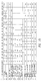
- FIG. 10 shows the filter characteristics of the dielectric filter obtained when the characteristic values of the elements in the equivalent circuits of the dielectric filter as the above-described model are changed in three phases, and the amounts of adjustment appropriate to the elements of the equivalent circuit obtained under a condition in which the characteristics are provided so as to obtain targeted filter characteristics.
- reference characters A 1 and A 2 indicate numbers given to the rows of items related to pass characteristics
- reference characters B 1 to B 7 indicate numbers given to the rows of items related to reflection characteristics
- reference characters C 1 to C 5 indicate numbers given to the rows of items related to various kinds of adjustments.
- FIG. 11 shows the relationship between the example of the filter characteristics and the characteristic values shown in FIG. 10 .
- the symbol [FO] indicates the central frequency of a pass band.
- the symbol [3 dB BW] indicates the width of the pass band, which is the width of a frequency attenuated by 3 dB from a minimum-loss level.
- the reference character [Bottom number] indicates the number of attenuations occurring in valley-wave forms in the reflection characteristics, generated in the vicinity of both sides of the pass band
- the reference character [Bottom 1 Freq.] indicates a frequency on the lower-frequency side in which the reflection characteristics are the smallest
- the reference character [Bottom 2 Freq.] indicates a frequency on the higher-frequency side in which the reflection characteristics are the smallest.
- the reference character [Bottom 1 Reflection Coefficient Factor] indicates a reflection coefficient at the frequency [Bottom 1 Freq.]
- the reference character [Bottom 2 Reflection Coefficient Factor] indicates a reflection coefficient at the frequency [Bottom 2 Freq.]
- the reference character [Flat Top Freq.] indicates a frequency whose reflection loss is the largest between the [Bottom 1 Freq.] and the [Bottom 2 Freq.]
- the reference character [Flat Top Reflection Coefficient Factor] indicates the coefficient of the reflection loss.
- FIG. 10 shows the above-described filter characteristics of eleven kinds of dielectric filters, in which the characteristic values of elements of the equivalent circuit of the dielectric filter are changed in three phases.
- the symbolic character Center shows targeted filter characteristics, in which adjusted amounts are zero.
- the symbolic character R 1 -low shows filter characteristics obtained when the resonant frequency of the resonator R 1 is low.
- a filter characteristic indicated by Center is obtained when a value of the amount of adjusting the resonator length L of the resonator R 1 is ⁇ 0.4 (when the resonator length decreases by 0.4) so as to increase the resonant frequency of the resonator R 1 .
- the symbolic character R 1 -high shows filter characteristics obtained when the resonant frequericy of the resonator R 1 is high.
- the filter characteristic indicated by Center is obtained when the value of the amount of adjusting the resonator length L of the resonator R 1 is +0.4 (when the resonator length increases by 0.4) so as to decrease the resonant frequency of the resonator R 1 .
- the same thing can be done in cases indicated by the symbolic characters R 2 -low and R 2 -high, which are equivalent to the cases of a low resonant frequency and a high resonant frequency, respectively, of the resonator R 2 .
- the symbolic character k 12 -low shows the case of a small coupling capacitance.
- a filter characteristic indicated by Center can be obtained when a value of the amount of adjusting the coupling apacitance value Ck 12 is +0.5 so as to increase the coupling capacitance.
- the symbolic character k 12 -high shows a case opposite to that situation.
- the symbolic character Qe 1 -low is equivalent to the case of a small coupling capacitance.
- the amount of adjusting the external-coupling capacitance value CQe 1 is set to be +0.6 so as to increase the coupling capacitance, by which a filter characteristic indicated by Center can be obtained.
- the symbolic character Qe 1 -high shows a case opposite to that situation.
- the symbolic characters Qe 2 -low and Qe 2 -high show cases of the other external coupling capacitances, in which the case of Qe 2 -low has a small external coupling capacitance and that of Qe 2 -high has a large external coupling capacitance.
- FIGS. 12A to 20 show examples of filter characteristics before adjustment of the characteristics shown in FIG. 10 .
- slender lines marked “A” indicate targeted characteristics of insertion losses and reflection losses, which are the characteristics of Center shown in FIG. 10 .
- the filter characteristics change according to the deviations of elements of the equivalent circuit.
- the amount of adjustment of the adjusted parts can be obtained from the characteristic values of the filter characteristics obtained by measuring the actual dielectric filter to be adjusted.
- the data shown in FIG. 10 is normalized, for instance, as shown in FIG. 15 .
- the values of “Center” and “R 1 -Low” in Table 10 are 1000.62 and 995.90.
- the value of “Center” is shifted from 1000.62 to O.
- the value of “R 1 -Low” is shifted from 995.90 to ⁇ 4.72, i.e., 995.90-1000.62.
- the data shown in FIG. 10 are “normalized” to the data in FIG. 15 by setting the value of the “Center” at a simple number.
- ⁇ FO indicates a deviation from the targeted value of a central frequency
- ⁇ 3 dB BW indicates a deviation from the targeted value of a pass-band width.
- ⁇ Bottom 1 Freq. indicates a deviation from the targeted value of Bottom 1 Freq.
- Bottom 1 Reflection Coefficient Ratio is a ratio with respect to a targeted Bottom 1 Reflection Coefficient.
- ⁇ Bottom 2 Freq indicates a deviation from the targeted value of Bottom 2 Freq.
- Bottom 2 Reflection Coefficient Ratio is a ratio with respect to a targeted Bottom 2 reflection coefficient.
- ⁇ Flat Top Freq. indicates a deviation from the targeted value of Flat Top Freq. and Flat Top Reflection Coefficient Ratio is a ratio with respect to a targeted Flat Top reflection coefficient.
- FIG. 16 shows a flowchart illustrating the actual procedure for creating the database as shown in FIG. 15 by measuring and adjusting the characteristics of a dielectric filter.
- a sample dielectric filter before adjustment of the characteristics is set in a tool and its filter characteristics are measured with a network analyzer.
- an adjusting device is controlled so as to set the filter characteristics in the specified range, and adjustments of each of the parts to be adjusted are performed by semi-manual operations. Since the adjustment work includes adjustments at a phase in which no database is created, no reference data exists. However, since there is a correlation to some extent between the amount of adjustment of adjusted parts and changes in the filter characteristics according to the adjustments, the filter characteristics become closer to targeted ones, little by little, every time adjustments are performed.
- FIGS. 12B and 12D when the central frequency is higher than a targeted value, adjustments are performed such that the resonant frequency of the resonators R 1 or R 2 is decreased.
- FIGS. 12B and 12C when the reflection characteristics of Bottom 1 are large (the reflection coefficient is large), adjustments are performed such that the resonant frequency of the resonator R 2 is increased or the resonant frequency of the resonator R 1 is decreased.
- FIG. 13B when the pass-band width is larger than a targeted value, adjustments are performed such that the coupling capacitance between the two resonators is decreased.
- the adjustments that are performed by semi-manual operations permit the filter characteristics to be set in a specified range near the targeted value
- the normalized data of the filter characteristics before adjustment of the characteristics and the amount of adjusting the adjusted parts are stored in the database.
- the above procedure is repeated on a plurality of the samples. Since there are variations in the filter characteristics of the dielectric filter before characteristic adjustments, the characteristics of the plurality of sample filters are adjusted, by which a database showing the relationships between the filter characteristics before adjustment of the characteristics and the appropriate amount of adjustment of the adjusted parts to obtain targeted filter characteristics is created.
- FIG. 17 is a flowchart illustrating the actual procedure for adjusting the characteristics at a phase in which the above-described database contains a substantial amount of data.
- a dielectric filter to be adjusted is set in a tool to measure the filter characteristics thereof. Adjustments after that are not necessary and the procedure is completed, if the filter characteristics are in a specified range which has the targeted value at the center. However, when the filter characteristics are not in that range, a pattern similar to the filter characteristics before adjustment of the characteristics, which are measured in this case, is extracted from the above-described normalized database. In this situation, the filter characteristics before adjustment of the characteristics, as shown in FIG. 15, are equivalent to normalized values based on the targeted characteristic values of the dielectric filter.
- the amount the adjusted parts are to be adjusted can be determined by extracting similar patterns.
- the higher the degree of similarity the higher a weight coefficient which is assigned to the amount of adjustment, and the larger the amount of one-time adjustment.
- the lower the degree of similarity the smaller the amount of one-time adjustment.
- the higher the degree of similarity the higher the weight coefficient with respect to the amount of adjustment, with the result that adjustment efficiency is enhanced.
- the degree of similarity is low, the accuracy of the amount of adjustment based on the database is low. Therefore, excessive adjustments can be prevented, because the method suppresses the amount of one-time adjustment, when the degree of similarity is low.
- the above-described procedure is repeated so as to set the filter characteristics in the specified range. Furthermore, when the filter characteristics are contained in the specified range by repeating adjustment of the characteristics, the first filter characteristics before adjustment of the characteristics and the cumulative amount of adjusting the adjusted parts are set as a pair of data to be normalized and stored in the database. The procedure is repeated to make adjustments of the characteristics of the dielectric filter so as to substantially increase the content of the database.
- the amount of data in the database is increased.
- the degree of similarity between the pattern of the filter characteristics before adjustment of the characteristics and the pattern of the database is small, new data is stored in the database, by which efficient adjustments of the characteristics can be performed even in a dielectric filter having various initial characteristics (the filter characteristics of the dielectric filter before adjustment of the characteristics), based on the database with a small amount of data.
- entering of data in the database may be prohibited.
- a band pass filter of two stages is used as an example.
- the present invention can similarly be applied to a dielectric duplexer comprising two dielectric filters, for example a duplexer produced by forming a conductive film on a single dielectric member such as a dielectric block.
- the characteristics of a transmitting filter part and the characteristics of a receiving filter part can be individually adjusted.
- the branch characteristics of an antenna port it is also possible to optimize the branch characteristics of an antenna port. This arrangement permits a dielectric duplexer with satisfactory branch characteristics to be easily produced, in which a transmitted signal can be prevented from passing through the receiving filter and a received signal can be prevented from passing through the transmitting filter.
Landscapes
- Engineering & Computer Science (AREA)
- Manufacturing & Machinery (AREA)
- Physics & Mathematics (AREA)
- Electromagnetism (AREA)
- Control Of Motors That Do Not Use Commutators (AREA)
Abstract
Description
Claims (20)
Applications Claiming Priority (4)
| Application Number | Priority Date | Filing Date | Title |
|---|---|---|---|
| JP11-063458 | 1999-03-10 | ||
| JP11063457A JP2000261206A (en) | 1999-03-10 | 1999-03-10 | Characteristic adjustment method for dielectric filter device, that for dielectric duplexer, and characteristic adjustment device for these dielectric filter device and duplexer |
| JP11063458A JP2000261205A (en) | 1999-03-10 | 1999-03-10 | Method for adjusting characteristic of dielectric filter device and method for adjusting characteristic of dielectric duplexer and device for adjusting characteristics of theses |
| JP11-063457 | 1999-03-10 |
Publications (1)
| Publication Number | Publication Date |
|---|---|
| US6504446B1 true US6504446B1 (en) | 2003-01-07 |
Family
ID=26404582
Family Applications (1)
| Application Number | Title | Priority Date | Filing Date |
|---|---|---|---|
| US09/523,030 Expired - Lifetime US6504446B1 (en) | 1999-03-10 | 2000-03-10 | Method for adjusting characteristics of dielectric filter, method for adjusting characteristics of dielectric duplexer, and devices for practicing the methods |
Country Status (1)
| Country | Link |
|---|---|
| US (1) | US6504446B1 (en) |
Cited By (17)
| Publication number | Priority date | Publication date | Assignee | Title |
|---|---|---|---|---|
| US6750733B1 (en) * | 2002-03-14 | 2004-06-15 | Agilent Technologies, Inc. | Coupled resonator filter tuning having inter-resonator interaction compensation |
| US9030278B2 (en) | 2011-05-09 | 2015-05-12 | Cts Corporation | Tuned dielectric waveguide filter and method of tuning the same |
| US9030279B2 (en) | 2011-05-09 | 2015-05-12 | Cts Corporation | Dielectric waveguide filter with direct coupling and alternative cross-coupling |
| US9130255B2 (en) | 2011-05-09 | 2015-09-08 | Cts Corporation | Dielectric waveguide filter with direct coupling and alternative cross-coupling |
| US9130258B2 (en) | 2013-09-23 | 2015-09-08 | Cts Corporation | Dielectric waveguide filter with direct coupling and alternative cross-coupling |
| US9130256B2 (en) | 2011-05-09 | 2015-09-08 | Cts Corporation | Dielectric waveguide filter with direct coupling and alternative cross-coupling |
| US9130257B2 (en) | 2010-05-17 | 2015-09-08 | Cts Corporation | Dielectric waveguide filter with structure and method for adjusting bandwidth |
| WO2016066183A1 (en) * | 2014-10-27 | 2016-05-06 | Nokia Solutions And Networks Oy | Tuning of filters |
| US9466864B2 (en) | 2014-04-10 | 2016-10-11 | Cts Corporation | RF duplexer filter module with waveguide filter assembly |
| US9583805B2 (en) | 2011-12-03 | 2017-02-28 | Cts Corporation | RF filter assembly with mounting pins |
| US9666921B2 (en) | 2011-12-03 | 2017-05-30 | Cts Corporation | Dielectric waveguide filter with cross-coupling RF signal transmission structure |
| US10050321B2 (en) | 2011-12-03 | 2018-08-14 | Cts Corporation | Dielectric waveguide filter with direct coupling and alternative cross-coupling |
| US10116028B2 (en) | 2011-12-03 | 2018-10-30 | Cts Corporation | RF dielectric waveguide duplexer filter module |
| US10483608B2 (en) | 2015-04-09 | 2019-11-19 | Cts Corporation | RF dielectric waveguide duplexer filter module |
| US10587030B2 (en) | 2016-11-08 | 2020-03-10 | LGS Innovations LLC | Systems and methods of designing, tuning and producing ceramic filters |
| US11081769B2 (en) | 2015-04-09 | 2021-08-03 | Cts Corporation | RF dielectric waveguide duplexer filter module |
| US11437691B2 (en) | 2019-06-26 | 2022-09-06 | Cts Corporation | Dielectric waveguide filter with trap resonator |
Citations (3)
| Publication number | Priority date | Publication date | Assignee | Title |
|---|---|---|---|---|
| US5528204A (en) * | 1994-04-29 | 1996-06-18 | Motorola, Inc. | Method of tuning a ceramic duplex filter using an averaging step |
| US5764116A (en) * | 1995-03-22 | 1998-06-09 | Murata Manufacturing Co., Ltd. | Dielectric resonator and filter utilizing a nonradiative dielectric waveguide device |
| US5815056A (en) * | 1993-12-21 | 1998-09-29 | Murata Manufacturing Co., Ltd. | Dielectric resonator having an elongated non-conductive resonator gaps and manufacturing method thereof |
-
2000
- 2000-03-10 US US09/523,030 patent/US6504446B1/en not_active Expired - Lifetime
Patent Citations (3)
| Publication number | Priority date | Publication date | Assignee | Title |
|---|---|---|---|---|
| US5815056A (en) * | 1993-12-21 | 1998-09-29 | Murata Manufacturing Co., Ltd. | Dielectric resonator having an elongated non-conductive resonator gaps and manufacturing method thereof |
| US5528204A (en) * | 1994-04-29 | 1996-06-18 | Motorola, Inc. | Method of tuning a ceramic duplex filter using an averaging step |
| US5764116A (en) * | 1995-03-22 | 1998-06-09 | Murata Manufacturing Co., Ltd. | Dielectric resonator and filter utilizing a nonradiative dielectric waveguide device |
Cited By (21)
| Publication number | Priority date | Publication date | Assignee | Title |
|---|---|---|---|---|
| US6750733B1 (en) * | 2002-03-14 | 2004-06-15 | Agilent Technologies, Inc. | Coupled resonator filter tuning having inter-resonator interaction compensation |
| US9130257B2 (en) | 2010-05-17 | 2015-09-08 | Cts Corporation | Dielectric waveguide filter with structure and method for adjusting bandwidth |
| US9431690B2 (en) | 2011-05-09 | 2016-08-30 | Cts Corporation | Dielectric waveguide filter with direct coupling and alternative cross-coupling |
| US9030278B2 (en) | 2011-05-09 | 2015-05-12 | Cts Corporation | Tuned dielectric waveguide filter and method of tuning the same |
| US9030279B2 (en) | 2011-05-09 | 2015-05-12 | Cts Corporation | Dielectric waveguide filter with direct coupling and alternative cross-coupling |
| US9130255B2 (en) | 2011-05-09 | 2015-09-08 | Cts Corporation | Dielectric waveguide filter with direct coupling and alternative cross-coupling |
| US9130256B2 (en) | 2011-05-09 | 2015-09-08 | Cts Corporation | Dielectric waveguide filter with direct coupling and alternative cross-coupling |
| US9437908B2 (en) | 2011-07-18 | 2016-09-06 | Cts Corporation | Dielectric waveguide filter with direct coupling and alternative cross-coupling |
| US10116028B2 (en) | 2011-12-03 | 2018-10-30 | Cts Corporation | RF dielectric waveguide duplexer filter module |
| US9583805B2 (en) | 2011-12-03 | 2017-02-28 | Cts Corporation | RF filter assembly with mounting pins |
| US9666921B2 (en) | 2011-12-03 | 2017-05-30 | Cts Corporation | Dielectric waveguide filter with cross-coupling RF signal transmission structure |
| US10050321B2 (en) | 2011-12-03 | 2018-08-14 | Cts Corporation | Dielectric waveguide filter with direct coupling and alternative cross-coupling |
| US9437909B2 (en) | 2013-09-23 | 2016-09-06 | Cts Corporation | Dielectric waveguide filter with direct coupling and alternative cross-coupling |
| US9130258B2 (en) | 2013-09-23 | 2015-09-08 | Cts Corporation | Dielectric waveguide filter with direct coupling and alternative cross-coupling |
| US9466864B2 (en) | 2014-04-10 | 2016-10-11 | Cts Corporation | RF duplexer filter module with waveguide filter assembly |
| WO2016066183A1 (en) * | 2014-10-27 | 2016-05-06 | Nokia Solutions And Networks Oy | Tuning of filters |
| US10333496B2 (en) | 2014-10-27 | 2019-06-25 | Nokia Solutions And Networks Oy | Tuning of filters |
| US10483608B2 (en) | 2015-04-09 | 2019-11-19 | Cts Corporation | RF dielectric waveguide duplexer filter module |
| US11081769B2 (en) | 2015-04-09 | 2021-08-03 | Cts Corporation | RF dielectric waveguide duplexer filter module |
| US10587030B2 (en) | 2016-11-08 | 2020-03-10 | LGS Innovations LLC | Systems and methods of designing, tuning and producing ceramic filters |
| US11437691B2 (en) | 2019-06-26 | 2022-09-06 | Cts Corporation | Dielectric waveguide filter with trap resonator |
Similar Documents
| Publication | Publication Date | Title |
|---|---|---|
| US6504446B1 (en) | Method for adjusting characteristics of dielectric filter, method for adjusting characteristics of dielectric duplexer, and devices for practicing the methods | |
| US9160045B2 (en) | Reconfigurable bandpass filter based on a planar combline filter comprising varactor diodes | |
| US20090121802A1 (en) | Systems and Methods for Tuning Filters | |
| Kuo et al. | Wideband bandpass filter design with three-line microstrip structures | |
| KR20000035337A (en) | A Method of and an Apparatus for Automatically Adjusting the Characteristics of a Dielectric Filter | |
| US7439748B2 (en) | Method and apparatus for measuring high-frequency electrical characteristics of electronic device, and method for calibrating apparatus for measuring high-frequency electrical characteristics | |
| US10763561B2 (en) | Band-pass filter and control method thereof | |
| US20220384931A1 (en) | Methods and apparatuses for tuning a filter | |
| US20070040561A1 (en) | Method and apparatus for measuring high-frequency electrical characteristics of electronic device, and method for calibrating apparatus for measuring high-frequency electrical characteristics | |
| US8629742B1 (en) | VHF harmonic impedance tuner | |
| Khan et al. | Parametric effect of defected ground structure (DGS) on frequency of a bandpass filter | |
| Sullca et al. | Design of dual stopband filters for interference suppression | |
| Mircea et al. | Impedance matching for UHF band antennas on ceramic substrate | |
| JP3912429B2 (en) | Method and apparatus for measuring high-frequency electrical characteristics of electronic components, and calibration method for high-frequency electrical characteristics measuring apparatus | |
| Schuster et al. | Fast and accurate tuning of a cross-coupled split-ring resonator filter | |
| RU2822306C1 (en) | Device for non-destructive microwave measurement of complex dielectric permeability of material of dielectric plates | |
| KR100451169B1 (en) | Filter design method using generic algorithm | |
| Golaszewski et al. | Design of varactor tuned bandpass filter | |
| CN120930381B (en) | A method for optimizing the communication performance of LTCC filters | |
| JP2000261206A (en) | Characteristic adjustment method for dielectric filter device, that for dielectric duplexer, and characteristic adjustment device for these dielectric filter device and duplexer | |
| Klimchuk | Milling Machine Validation through Microstrip Filter Manufacturing | |
| US6522224B2 (en) | Method for adjusting characteristics of a dielectric filter | |
| RU2174737C2 (en) | Microwave bandpass filter | |
| JP2000261205A (en) | Method for adjusting characteristic of dielectric filter device and method for adjusting characteristic of dielectric duplexer and device for adjusting characteristics of theses | |
| Andreev et al. | Study of Perspective of Gaseous Dielectric Parameters Monitoring with Use of Coupled Biconical Resonators |
Legal Events
| Date | Code | Title | Description |
|---|---|---|---|
| AS | Assignment |
Owner name: MURATA MANUFACTURING CO., LTD., JAPAN Free format text: ASSIGNMENT OF ASSIGNORS INTEREST;ASSIGNORS:ISHIHARA, JINSEI;KATO, HIDEYUKI;REEL/FRAME:010917/0382;SIGNING DATES FROM 20000412 TO 20000413 |
|
| AS | Assignment |
Owner name: MURATA MANUFACTURING CO., LTD., JAPAN Free format text: ASSIGNMENT OF ASSIGNORS INTEREST;ASSIGNORS:ISHIHARA, JINSEI;KATO, HIDEYUKI;REEL/FRAME:011663/0665 Effective date: 20000413 |
|
| STCF | Information on status: patent grant |
Free format text: PATENTED CASE |
|
| FPAY | Fee payment |
Year of fee payment: 4 |
|
| FEPP | Fee payment procedure |
Free format text: PAYOR NUMBER ASSIGNED (ORIGINAL EVENT CODE: ASPN); ENTITY STATUS OF PATENT OWNER: LARGE ENTITY |
|
| FPAY | Fee payment |
Year of fee payment: 8 |
|
| FPAY | Fee payment |
Year of fee payment: 12 |