US6494481B2 - Airbag apparatus for front passenger seat - Google Patents
Airbag apparatus for front passenger seat Download PDFInfo
- Publication number
- US6494481B2 US6494481B2 US09/836,664 US83666401A US6494481B2 US 6494481 B2 US6494481 B2 US 6494481B2 US 83666401 A US83666401 A US 83666401A US 6494481 B2 US6494481 B2 US 6494481B2
- Authority
- US
- United States
- Prior art keywords
- fracture
- airbag
- opening section
- instrument panel
- opening
- Prior art date
- Legal status (The legal status is an assumption and is not a legal conclusion. Google has not performed a legal analysis and makes no representation as to the accuracy of the status listed.)
- Expired - Lifetime
Links
Images


Classifications
-
- B—PERFORMING OPERATIONS; TRANSPORTING
- B60—VEHICLES IN GENERAL
- B60R—VEHICLES, VEHICLE FITTINGS, OR VEHICLE PARTS, NOT OTHERWISE PROVIDED FOR
- B60R21/00—Arrangements or fittings on vehicles for protecting or preventing injuries to occupants or pedestrians in case of accidents or other traffic risks
- B60R21/02—Occupant safety arrangements or fittings, e.g. crash pads
- B60R21/16—Inflatable occupant restraints or confinements designed to inflate upon impact or impending impact, e.g. air bags
- B60R21/20—Arrangements for storing inflatable members in their non-use or deflated condition; Arrangement or mounting of air bag modules or components
- B60R21/217—Inflation fluid source retainers, e.g. reaction canisters; Connection of bags, covers, diffusers or inflation fluid sources therewith or together
-
- B—PERFORMING OPERATIONS; TRANSPORTING
- B60—VEHICLES IN GENERAL
- B60R—VEHICLES, VEHICLE FITTINGS, OR VEHICLE PARTS, NOT OTHERWISE PROVIDED FOR
- B60R21/00—Arrangements or fittings on vehicles for protecting or preventing injuries to occupants or pedestrians in case of accidents or other traffic risks
- B60R21/02—Occupant safety arrangements or fittings, e.g. crash pads
- B60R21/16—Inflatable occupant restraints or confinements designed to inflate upon impact or impending impact, e.g. air bags
- B60R21/20—Arrangements for storing inflatable members in their non-use or deflated condition; Arrangement or mounting of air bag modules or components
- B60R21/215—Arrangements for storing inflatable members in their non-use or deflated condition; Arrangement or mounting of air bag modules or components characterised by the covers for the inflatable member
- B60R21/2165—Arrangements for storing inflatable members in their non-use or deflated condition; Arrangement or mounting of air bag modules or components characterised by the covers for the inflatable member characterised by a tear line for defining a deployment opening
Definitions
- the present invention relates to an airbag apparatus for a front passenger seat for protecting a passenger sitting in the front passenger seat upon collision of a vehicle, such as a car, to thereby ensure safety of the passenger. More particularly, the invention relates to an improvement in the structure of a fracture-opening section formed on the cover of an instrument panel in opposition to an airbag accommodated within an airbag apparatus for a front passenger seat which, in turn, is accommodated within the instrument panel. Upon collision of the vehicle, the airbag,inflates out of the instrument panel while breaking open the fracture-opening section, so as to protect the passenger.
- An airbag apparatus for a front passenger seat of a vehicle basically includes an airbag, an airbag case for accommodating the folded airbag, and an inflater for inflating the airbag.
- the airbag apparatus is accommodated within an instrument panel in opposition to the front passenger seat.
- the instrument panel cover includes a cover plate having a size corresponding to that of an opening portion of the airbag case as disclosed in Japanese Patent Application Laid-Open (kokai) No. 7-172256 or includes a lid plate as proposed by the inventors of the present invention in Japanese Patent Application No. 10-7979.
- the lid plate is located in opposition to the opening portion of the airbag case and is formed integrally with the instrument panel cover.
- the main body of a lid reinforcement is fixedly attached to the lid plate from inside along a peripheral edge portion of the lid plate. A portion of the reinforcement which extends from a hinge portion of the reinforcement extending upward from the main body of the reinforcement is fixedly attached to the airbag case via a bracket. Upon inflation of the airbag, the cover plate or the lid plate is opened.
- the thus-configured airbag apparatus for a front passenger seat functions in the following manner.
- an impact force caused by the collision is detected by a sensor.
- a control unit including a CPU judges whether or not the detected impact force is equal to or higher than a predetermined value.
- the control unit judges that the impact force is not lower than the predetermined value, the control unit issues a signal for causing the inflater to generate a predetermined gas. The gas is fed to the airbag so as to promptly inflate the airbag.
- the inflating airbag presses, from inside, a fracture-opening lid, such as the cover plate or the lid plate, of the instrument panel cover.
- the lid is fractured along a fracture line and detached from the instrument panel cover.
- the detached lid is opened outward while being turned inside out about the hinge portion of the lid reinforcement.
- the inflating airbag projects outward from the instrument panel cover through the thus-formed opening in the instrument panel cover. Serving as a cushion, the inflated airbag supports a front seat passenger at his/her chest and head, thereby protecting the passenger from the impact force of collision.
- the conventional instrument panel of a vehicle has a fracture-opening lid formed thereon in such a manner as to face the front passenger seat of the vehicle; i.e., the lid is formed on an inclined plane of the instrument panel which faces a front seat passenger.
- the fracture-opening lid Upon inflation of the airbag, the fracture-opening lid is detached from the inclined plane.
- the detached lid is opened outward while being turned inside out about the hinge portion of the lid reinforcement.
- the inflating airbag projects outward from the instrument panel. An edge of the thus-detached lid may injure the front seat passenger.
- detachment of the lid occurs in the vicinity of the face of the child, thus doubling the degree of danger.
- FIG. 1 An airbag apparatus for a front passenger seat as shown in FIG. 1 has been developed.
- An airbag apparatus for a front passenger seat 1 shown in FIG. 1 is disposed within an instrument panel such that an airbag 4 inflated by means of gas from an inflater projects from a substantially horizontal plane 3 a of an instrument panel cover 3 located in the vicinity of a windshield la of a vehicle.
- the airbag apparatus includes an airbag case 5 adapted to accommodate the folded airbag 4 and having an opening portion 5 a formed in opposition to the back surface of the instrument panel cover 3 .
- a flexible fracture-opening lid 6 formed of a synthetic resin is disposed at an opening portion 3 b formed on the instrument panel cover 3 in opposition to the opening portion 5 a of the airbag case 5 .
- the fracture-opening lid 6 Upon inflation of the airbag 4 , the fracture-opening lid 6 is split open into two fracture pieces, which open apart in opposite directions toward the front and rear of the vehicle, respectively, through fracture along grooves 6 a and 6 b , which are formed along the centerline of and the periphery of the fracture-opening lid 6 and serve as fragile portions.
- the inflating airbag 4 projects outward through the thus-formed opening.
- a mounting leg portion 7 and a plurality of engagement pieces 8 are integrally formed on the back surface of the fracture-opening lid 6 .
- the mounting leg portion 7 assumes the form of a rectangular frame slightly greater in size than the opening portion 5 a of the airbag case 5 .
- the engagement pieces 8 are elastically engaged with the edge of the opening portion 3 b of the instrument panel cover 3 .
- a plurality of rectangular through-holes 7 c are formed in a front wall 7 a of and in a rear wall 7 b of the mounting leg portion 7 .
- the rectangular through-holes 7 c are engaged with corresponding hooks 9 fixedly attached to a front wall 5 b of and to a rear wall 5 b of the opening portion 5 a of the airbag case 5 .
- the fracture-opening lid 6 Upon inflation of the airbag 4 , the fracture-opening lid 6 is split open into two fracture pieces, which open apart in opposite directions toward the front and rear of the vehicle, respectively, through fracture along the grooves 6 a and 6 b , which are formed along the centerline of and the periphery of the fracture-opening lid 6 . Since the rectangular through-holes 7 c formed in the front and rear walls 7 a and 7 c of the mounting leg portion 7 are engaged with the hooks 9 fixedly attached to the front and rear walls 5 b of the opening portion 5 a of the airbag case 5 , scattering of the fracture pieces of the fracture-opening lid 6 is prevented.
- the opening portion 3 b is formed in the instrument panel cover 3 in such a manner as to face the opening portion 5 a of the airbag case 5 .
- the fracture-opening lid 6 is a discrete element different from the instrument panel cover 3 and made of a flexible resin material and is fitted into the opening portion 3 b .
- the manufacture and the assembly work of the instrument panel cover 3 and the fracture-opening lid 6 are rather complicated.
- the fracture-opening lid 6 easily deforms when an external force is applied thereto, thereby damaging the appearance or design of the instrument panel cover 3 .
- the discrete fracture-opening lid 6 is not reinforced from behind. Since the fracture-opening lid 6 is made of a flexible material, upon inflation of the airbag 4 , the leg portion 7 is likely to disengage from the hooks 9 fixedly attached to the front and rear walls 5 b of the opening portion 5 a of the airbag case 5 , potentially involving scattering of fracture pieces of the fracture-opening lid 6 .
- An object of the present invention is to solve the above-mentioned problems in the conventional airbag apparatus for a front passenger seat and to provide an airbag apparatus for a front passenger seat which can be manufactured and assembled easily, whose fracture-opening section can be fractured reliably upon inflation of an airbag while maintaining high safety, and which has an improved appearance.
- the present invention provides an airbag apparatus for a front passenger seat built in an instrument panel of a vehicle, comprising: an airbag case accommodated within a core of the instrument panel and having an opening portion located in opposition to a back surface of a cover of the instrument panel; an airbag accommodated within the airbag case in a folded state, the airbag being able to be inflated by means of gas from an inflater; a fracture-opening section defined in the cover to be located in opposition to the opening portion of the airbag case, the fracture-opening section having a fragile contour portion surrounding the fracture-opening section and a fragile splitting portion for dividing t he fracture-opening section into first and second subsections; and first and second reinforcements fixedly attached to back surfaces of the first and second subsections, each of the first and second reinforcements having a hinge portion and a leg portion whose end is engaged with a hook fixedly attached to the opening portion of the airbag case, whereby the fracture-opening section opens apart along the fragile splitting portion upon inflation of
- the above configuration facilitates manufacture, allows the fracture-opening section to be reliably fractured along the contour portion and the splitting portion while maintaining high safety, and imparts favorable appearance or de sign to the instrument panel.
- FIG. 1 is a perspective view showing a conventional instrument panel cover having a fracture-opening section for allowing an inflating airbag to project outward therethrough;
- FIG. 2 is a vertical sectional view of a conventional airbag apparatus for a front passenger seat taken along line II—II of FIG. 1;
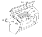
- FIG. 3 is a perspective view of a main portion of an instrument panel cover equipped with an airbag apparatus for a front passenger seat according to an embodiment of the present invention
- FIG. 4 is a vertical sectional view of the airbag apparatus of the embodiment taken along line IV—IV of FIG. 3;
- FIG. 5 is a partial plan view of an instrument panel cover including a fracture-opening section which partially constitutes the airbag apparatus of the embodiment;
- FIG. 6 is a perspective view of a main portion of the airbag apparatus of the embodiment, showing reinforcements as observed upon initiation of the airbag apparatus;
- FIG. 7 is a partial plan view of an instrument panel cover showing a modified example of the fracture-opening section which partially constitutes the airbag apparatus according to the embodiment.
- FIG. 8 is a partial plan view of an instrument panel cover showing another modified example of the fracture-opening section which partially constitutes the airbag apparatus according to the embodiment.
- front and rear correspond to the front and rear, respectively, of a vehicle
- right and left correspond to the right-hand and left-hand sides, respectively, of the vehicle.
- an instrument panel 10 includes an instrument panel core 12 and an instrument panel cover 11 , which covers the instrument panel core 12 .
- the instrument panel core 12 and the instrument panel cover 11 are each molded from a synthetic resin, such as polypropylene.
- the instrument panel cover 11 is fixedly attached, by appropriate means, such as tapping screws, to the instrument panel core 12 , which, in turn, is fixedly attached to a frame (not shown) of a vehicle.
- an accommodation section 21 for accommodating a metallic airbag case 20 is defined by means of a partition 22 behind the instrument panel cover 11 and located in opposition to a front seat passenger seat.
- the present embodiment is applied to a right-hand drive.
- a left-hand drive employs a mirror image of the configuration of the present embodiment.
- the partition 22 is removably attached to the instrument panel cover 11 using a plurality of tapping screws in order to facilitate the attachment of the airbag case 20 and other elements to the instrument panel cover 11 .
- a fracture-opening section 30 which is split open upon inflation of an airbag, is formed on the instrument panel cover 11 in opposition to the accommodation section 21 .
- the fracture-opening section 30 assumes a substantially rectangular shape and an area substantially equal to that of an opening portion 23 of the airbag case 20 .
- the fracture-opening section 30 can be split into two pieces along a splitting portion 30 b , which includes fragile portions formed through laser processing, which will be described later.
- the airbag case 20 is accommodated within the accommodation section 21 in the following manner.
- a plurality of hooks 24 are fixedly attached in a row to front and rear walls 23 a and 23 b of the opening portion 23 of the airbag case 20 .
- Each of the hooks 24 is bent outward at an upper end portion.
- a pair of reinforcements 33 are fixedly attached, at respective end portions, to the back surface of the fracture-opening section 30 through thermal bonding or like processing.
- the reinforcements 30 each include a hinge portion 34 and a leg portion 34 a extending downward from the hinge portion 34 ; i.e., extending away from the fixedly attached end portion.
- a plurality of slots 34 b are formed in the leg portion 34 a of each reinforcement 33 in such a manner as to extend therethrough in the front-rear direction.
- the hooks 24 are engaged with the corresponding slots 34 b through utilization of the elasticity of the leg portions 34 a .
- a lower end portion of the airbag case 20 is fixedly attached to the partition 22 by means of bolts and nuts 26 .
- An airbag 27 is accommodated in a folded condition within the airbag case 20 .
- the airbag 27 is connected to an inflater (not shown) disposed outside the partition 22 , by means of a gas feed pipe 28 .
- the airbag protection cover 29 is adapted to prevent the folded airbag 27 from coming out from the airbag case 20 and breaks easily upon inflation of the airbag 27 .
- the fracture-opening section 30 includes a splitting portion 30 b , which extends in the right-and-left direction at a substantially central portion while dividing the fracture-opening section 30 into a front subsection 31 and a rear subsection 32 .
- the splitting portion 30 b is biased toward the front passenger seat such that, between the two subsections 31 and 32 of the fracture-opening section 30 , the subsection 32 located on the side of the front passenger seat of the vehicle is slightly smaller in area than the other subsection 31 located on the side of the windshield of the vehicle.
- a contour portion 30 a of and the splitting portion 30 b of the fracture-opening section 30 include fragile portions formed by means of a laser (not shown). Specifically, a pulsating laser beam is applied from behind the instrument panel cover 11 while being moved relatively along the contour portion 30 a and the splitting portion 30 b to thereby form the fragile portions.
- the two reinforcements 33 are fixedly attached to the back surfaces of the subsections 31 and 32 of the fracture-opening section 30 through thermal bonding or like processing. Upon inflation of the airbag 27 , the fracture-opening portion 30 is split open such that the subsections 31 and 32 are turned inside out about the hinge portions of the reinforcements 33 in opposite directions.
- one reinforcement 33 assumes a substantially rectangular shape corresponding to that of the subsection 31 of the fracture-opening section 30
- the other reinforcement 33 assumes a substantially rectangular shape corresponding to that of the subsection 32 of the fracture-opening section 30
- the reinforcements 33 each include the hinge portion 34 extending in the longitudinal direction and the leg portion 34 a extending downward from the hinge portion 34 .
- the leg portion 34 a has the slots 34 b formed therein in such a manner as to extend therethrough in the front-rear direction and to be arranged in a row in the longitudinal direction.
- the slots 34 b are engaged with the plurality of hooks 24 fixedly attached at constant intervals to the front and rear walls 23 a and 23 b of the airbag case 20 .
- the slots 34 b and the hooks 24 are engaged such that a gap of 4 mm to 7 mm is formed between the hook 24 and the bottom of the slot 34 b.
- a plurality of depressions 35 are formed, for reinforcement purpose, on each of the reinforcements 33 in such a manner as to extend in the short-side direction of the reinforcement 33 and to be arranged at certain intervals in the long-side direction of the reinforcement 33 .
- Blocks of coupling holes 36 are formed on each of the reinforcements 33 while being arranged in the short-side and long-side directions of the reinforcement 33 .
- Each block includes a plurality of coupling holes 36 extending in the short-side direction of the reinforcement 33 and arranged close to one another in the short-side and long-side directions of the reinforcement 33 .
- Protrusions 33 a and 33 b are respectively formed at the facing end portions of the reinforcements 33 such that the protrusions 33 a and 33 b are alternately arranged along the splitting portion 30 b of the fracture-opening section 30 .
- the upper end of the opening portion 23 of the airbag case 20 is located in the vicinity of the back surface of the fracture-opening section 30 such that the airbag 27 accommodated within the airbag case 20 abuts the fragile portions of the contour portion 30 a and the fragile portions of the splitting portion 30 b via the reinforcements 33 to thereby reinforce the fragile portions against an external force to be potentially applied to the instrument panel cover 11 , on which the fragile portions are formed.
- a plurality of elongated protrusions 37 are formed on the inner surfaces of the subsections 31 and 32 of the fracture-opening section 30 in such a manner as to be aligned with the coupling holes 36 formed on the reinforcements 33 .
- the elongated protrusions 37 are engaged with the corresponding coupling holes 36 , and the tip ends of the protrusions 37 are melted through application of heat, such that the tip ends are flattened.
- the reinforcements 33 are fixedly attached to the corresponding front and rear subsections 31 and 32 .
- the contour portion 30 a and the splitting portion 30 b of the fracture-opening section 30 which is split open upon inflation of the airbag 27 , are formed on the instrument panel cover 11 by means of a laser.
- a pulsating laser beam output: 3 kW to 5 kW
- a predetermined frequency e.g., 7 kHz
- groove-like fragile portions are formed on the instrument panel cover 11 according to the relative speed of movement of and the pulsation pattern of a laser beam emitted from the laser.
- grooves serving as fragile portions are formed on the instrument panel cover 11 at a certain pattern along the entire outline edge of the reinforcement 33 .
- the thus-formed fragile portions define the contour portion 30 a and the splitting portion 30 b , along which the fracture-opening section 30 fractures upon inflation of the airbag 27 .
- the subsection 32 of the fracture-opening section 30 which is located on the side of the front passenger seat of a vehicle, assumes such a size as not to project beyond the instrument panel cover 11 toward the passenger seat upon inflation of the airbag 27 .
- the thus-configured airbag apparatus for a front passenger seat functions in the following manner.
- an impact force caused by the collision is detected by a sensor.
- a control unit including a CPU judges whether or not the detected impact force is equal to or higher than a predetermined value.
- the control unit judges that the impact force is not lower than the predetermined value, the control unit issues a signal for causing the inflater to generate a predetermined gas.
- the gas is fed to the airbag 27 so as to promptly inflate the airbag 27 .
- the inflating airbag 27 presses, from inside, the fracture-opening section 30 of the instrument panel cover 11 .
- the front and rear subsections 31 and 32 of the fracture-opening section 30 are fractured along the contour portion 30 a and the splitting portion 30 b and detached from the instrument panel cover 11 .
- the detached front and rear subsections 31 and 32 are opened outward while being turned inside out about the hinge portions 34 of the reinforcements 33 . Since the slots 34 b formed in the leg portions 34 a of the reinforcements 33 are engaged with the hooks 24 of the airbag case 20 , scattering of the subsections 31 and 32 is prevented.
- the inflating airbag 27 projects outward from the instrument panel cover 11 through the thus-formed opening in the instrument panel cover 11 . Serving as a cushion, the inflated airbag 27 supports a front seat passenger at his/her chest and head, thereby protecting the passenger from the impact force of collision.
- the fracture-opening section 30 is formed on the back surface of the instrument panel cover 11 such that the fracture-opening section 30 can be fractured along the contour portion 30 a and the splitting portion 30 b composed of fragile portions, which are formed through laser processing.
- the fracture-opening portion 30 is invisible on the surface of a substantially horizontal plane 11 b of the instrument panel cover 11 , thereby enhancing the design of the instrument panel cover 11 and enabling reliable, prompt fracture of the fracture-opening section 30 upon inflation of the airbag 27 .
- the right-hand and left-hand contour portions 30 a including fragile portions, of the front and rear subsections 31 and 32 of the fracture-opening section 30 each assume the form of a combination of convex curves L terminating at an end 30 c of the splitting portion 30 b or the form of a combination of a convex curve L and a straight line S terminating at the end 30 c of the splitting portion 30 b , such that the opening portion 11 d of the panel cover 11 has a projecting portion 11 e in opposition to the end 30 c of the splitting portion 30 b , and the splitting portion 30 b is located in a manner biased toward the front passenger seat of the vehicle.
- the fragile portions formed at the contour portion 30 a of and at the splitting portion 30 b of the fracture-opening section 30 are formed such that a laser beam is applied to the instrument panel cover 11 from behind while being moved relatively along the contour portion 30 a and the splitting portion 30 b .
- the present invention is not limited thereto.
- grooves which serve as the fragile portions may be formed on the back surface of the instrument panel cover 11 by means of a mold.
- the subsections of the fracture-opening section into which the fracture-opening section is split upon inflation of the airbag are reliably connected to the airbag case by means of the corresponding reinforcements. Therefore, the subsections do not scatter off.
- the fracture-opening section is formed on a substantially horizontal portion of the instrument panel cover located in the vicinity of the windshield, upon inflation of the airbag, subsections of the fracture-opening section do not reach a front seat passenger, to thereby prevent potential injury to the passenger by an edge of a subsection.
- the fracture-opening section fractures sufficiently away from the face of the child, thereby avoiding endangering the child.
Landscapes
- Engineering & Computer Science (AREA)
- Mechanical Engineering (AREA)
- Air Bags (AREA)
Abstract
The airbag apparatus includes a fracture-opening section of an instrument panel cover located in opposition to an opening portion of an airbag case and capable of being split apart, and a plurality of reinforcements fixedly attached to the back surface of the fracture-opening section. The fracture-opening section includes a contour portion and a splitting portion, which, in turn, include fragile portions formed through laser processing. The reinforcements are attached to the fracture-opening section in such a manner as to correspond to subsections of the fracture-opening section into which the splitting portion divides the fracture-opening section. The reinforcements each include a hinge portion and a leg portion. An end of the leg portion is engaged with a plurality of hooks fixedly attached to side edges of the opening portion of the airbag case. Upon inflation of the airbag, the fracture-opening section opens apart along the splitting portion.
Description
1. Field of the Invention
The present invention relates to an airbag apparatus for a front passenger seat for protecting a passenger sitting in the front passenger seat upon collision of a vehicle, such as a car, to thereby ensure safety of the passenger. More particularly, the invention relates to an improvement in the structure of a fracture-opening section formed on the cover of an instrument panel in opposition to an airbag accommodated within an airbag apparatus for a front passenger seat which, in turn, is accommodated within the instrument panel. Upon collision of the vehicle, the airbag,inflates out of the instrument panel while breaking open the fracture-opening section, so as to protect the passenger.
2. Description of the Related Art
An airbag apparatus for a front passenger seat of a vehicle, such as a car, basically includes an airbag, an airbag case for accommodating the folded airbag, and an inflater for inflating the airbag. The airbag apparatus is accommodated within an instrument panel in opposition to the front passenger seat.
The instrument panel cover includes a cover plate having a size corresponding to that of an opening portion of the airbag case as disclosed in Japanese Patent Application Laid-Open (kokai) No. 7-172256 or includes a lid plate as proposed by the inventors of the present invention in Japanese Patent Application No. 10-7979. According to Japanese Patent Application No. 10-7979, the lid plate is located in opposition to the opening portion of the airbag case and is formed integrally with the instrument panel cover. The main body of a lid reinforcement is fixedly attached to the lid plate from inside along a peripheral edge portion of the lid plate. A portion of the reinforcement which extends from a hinge portion of the reinforcement extending upward from the main body of the reinforcement is fixedly attached to the airbag case via a bracket. Upon inflation of the airbag, the cover plate or the lid plate is opened.
The thus-configured airbag apparatus for a front passenger seat functions in the following manner. Upon collision of the vehicle, an impact force caused by the collision is detected by a sensor. A control unit including a CPU judges whether or not the detected impact force is equal to or higher than a predetermined value. When the control unit judges that the impact force is not lower than the predetermined value, the control unit issues a signal for causing the inflater to generate a predetermined gas. The gas is fed to the airbag so as to promptly inflate the airbag.
The inflating airbag presses, from inside, a fracture-opening lid, such as the cover plate or the lid plate, of the instrument panel cover. The lid is fractured along a fracture line and detached from the instrument panel cover. The detached lid is opened outward while being turned inside out about the hinge portion of the lid reinforcement.
The inflating airbag projects outward from the instrument panel cover through the thus-formed opening in the instrument panel cover. Serving as a cushion, the inflated airbag supports a front seat passenger at his/her chest and head, thereby protecting the passenger from the impact force of collision.
Generally, the conventional instrument panel of a vehicle has a fracture-opening lid formed thereon in such a manner as to face the front passenger seat of the vehicle; i.e., the lid is formed on an inclined plane of the instrument panel which faces a front seat passenger. Upon inflation of the airbag, the fracture-opening lid is detached from the inclined plane. The detached lid is opened outward while being turned inside out about the hinge portion of the lid reinforcement. The inflating airbag projects outward from the instrument panel. An edge of the thus-detached lid may injure the front seat passenger. When the passenger is a child, detachment of the lid occurs in the vicinity of the face of the child, thus doubling the degree of danger.
In order to prevent the above danger, an airbag apparatus for a front passenger seat as shown in FIG. 1 has been developed.
An airbag apparatus for a front passenger seat 1 shown in FIG. 1 is disposed within an instrument panel such that an airbag 4 inflated by means of gas from an inflater projects from a substantially horizontal plane 3 a of an instrument panel cover 3 located in the vicinity of a windshield la of a vehicle. The airbag apparatus includes an airbag case 5 adapted to accommodate the folded airbag 4 and having an opening portion 5 a formed in opposition to the back surface of the instrument panel cover 3. A flexible fracture-opening lid 6 formed of a synthetic resin is disposed at an opening portion 3 b formed on the instrument panel cover 3 in opposition to the opening portion 5 a of the airbag case 5. Upon inflation of the airbag 4, the fracture-opening lid 6 is split open into two fracture pieces, which open apart in opposite directions toward the front and rear of the vehicle, respectively, through fracture along grooves 6 a and 6 b, which are formed along the centerline of and the periphery of the fracture-opening lid 6 and serve as fragile portions. The inflating airbag 4 projects outward through the thus-formed opening.
A mounting leg portion 7 and a plurality of engagement pieces 8 are integrally formed on the back surface of the fracture-opening lid 6. The mounting leg portion 7 assumes the form of a rectangular frame slightly greater in size than the opening portion 5 a of the airbag case 5. The engagement pieces 8 are elastically engaged with the edge of the opening portion 3 b of the instrument panel cover 3. A plurality of rectangular through-holes 7 c are formed in a front wall 7 a of and in a rear wall 7 b of the mounting leg portion 7. When the fracture-opening lid 6 is fitted to the opening portion 3 b of the instrument panel cover 3, the rectangular through-holes 7 c are engaged with corresponding hooks 9 fixedly attached to a front wall 5 b of and to a rear wall 5 b of the opening portion 5 a of the airbag case 5.
Upon inflation of the airbag 4, the fracture-opening lid 6 is split open into two fracture pieces, which open apart in opposite directions toward the front and rear of the vehicle, respectively, through fracture along the grooves 6 a and 6 b, which are formed along the centerline of and the periphery of the fracture-opening lid 6. Since the rectangular through-holes 7 c formed in the front and rear walls 7 a and 7 c of the mounting leg portion 7 are engaged with the hooks 9 fixedly attached to the front and rear walls 5 b of the opening portion 5 a of the airbag case 5, scattering of the fracture pieces of the fracture-opening lid 6 is prevented.
According to the airbag apparatus for a front passenger seat shown in FIG. 1, the opening portion 3 b is formed in the instrument panel cover 3 in such a manner as to face the opening portion 5 a of the airbag case 5. The fracture-opening lid 6 is a discrete element different from the instrument panel cover 3 and made of a flexible resin material and is fitted into the opening portion 3 b. Thus, the manufacture and the assembly work of the instrument panel cover 3 and the fracture-opening lid 6 are rather complicated. Also, the fracture-opening lid 6 easily deforms when an external force is applied thereto, thereby damaging the appearance or design of the instrument panel cover 3.
Also, the discrete fracture-opening lid 6 is not reinforced from behind. Since the fracture-opening lid 6 is made of a flexible material, upon inflation of the airbag 4, the leg portion 7 is likely to disengage from the hooks 9 fixedly attached to the front and rear walls 5 b of the opening portion 5 a of the airbag case 5, potentially involving scattering of fracture pieces of the fracture-opening lid 6.
An object of the present invention is to solve the above-mentioned problems in the conventional airbag apparatus for a front passenger seat and to provide an airbag apparatus for a front passenger seat which can be manufactured and assembled easily, whose fracture-opening section can be fractured reliably upon inflation of an airbag while maintaining high safety, and which has an improved appearance.
In order to achieve the above object, the present invention provides an airbag apparatus for a front passenger seat built in an instrument panel of a vehicle, comprising: an airbag case accommodated within a core of the instrument panel and having an opening portion located in opposition to a back surface of a cover of the instrument panel; an airbag accommodated within the airbag case in a folded state, the airbag being able to be inflated by means of gas from an inflater; a fracture-opening section defined in the cover to be located in opposition to the opening portion of the airbag case, the fracture-opening section having a fragile contour portion surrounding the fracture-opening section and a fragile splitting portion for dividing t he fracture-opening section into first and second subsections; and first and second reinforcements fixedly attached to back surfaces of the first and second subsections, each of the first and second reinforcements having a hinge portion and a leg portion whose end is engaged with a hook fixedly attached to the opening portion of the airbag case, whereby the fracture-opening section opens apart along the fragile splitting portion upon inflation of the airbag.
The above configuration facilitates manufacture, allows the fracture-opening section to be reliably fractured along the contour portion and the splitting portion while maintaining high safety, and imparts favorable appearance or de sign to the instrument panel.
FIG. 1 is a perspective view showing a conventional instrument panel cover having a fracture-opening section for allowing an inflating airbag to project outward therethrough;
FIG. 2 is a vertical sectional view of a conventional airbag apparatus for a front passenger seat taken along line II—II of FIG. 1;
FIG. 3 is a perspective view of a main portion of an instrument panel cover equipped with an airbag apparatus for a front passenger seat according to an embodiment of the present invention;
FIG. 4 is a vertical sectional view of the airbag apparatus of the embodiment taken along line IV—IV of FIG. 3;
FIG. 5 is a partial plan view of an instrument panel cover including a fracture-opening section which partially constitutes the airbag apparatus of the embodiment;
FIG. 6 is a perspective view of a main portion of the airbag apparatus of the embodiment, showing reinforcements as observed upon initiation of the airbag apparatus;
FIG. 7 is a partial plan view of an instrument panel cover showing a modified example of the fracture-opening section which partially constitutes the airbag apparatus according to the embodiment; and
FIG. 8 is a partial plan view of an instrument panel cover showing another modified example of the fracture-opening section which partially constitutes the airbag apparatus according to the embodiment.
An embodiment of the present invention will next be described in detail with reference to the drawings.
In the present specification, the terms “front” and “rear” correspond to the front and rear, respectively, of a vehicle, and the terms “right” and “left” correspond to the right-hand and left-hand sides, respectively, of the vehicle.
As shown in FIGS. 3 and 4, an instrument panel 10 includes an instrument panel core 12 and an instrument panel cover 11, which covers the instrument panel core 12. The instrument panel core 12 and the instrument panel cover 11 are each molded from a synthetic resin, such as polypropylene. The instrument panel cover 11 is fixedly attached, by appropriate means, such as tapping screws, to the instrument panel core 12, which, in turn, is fixedly attached to a frame (not shown) of a vehicle.
As shown in FIG. 4, an accommodation section 21 for accommodating a metallic airbag case 20 is defined by means of a partition 22 behind the instrument panel cover 11 and located in opposition to a front seat passenger seat. The present embodiment is applied to a right-hand drive. A left-hand drive employs a mirror image of the configuration of the present embodiment.
The partition 22 is removably attached to the instrument panel cover 11 using a plurality of tapping screws in order to facilitate the attachment of the airbag case 20 and other elements to the instrument panel cover 11.
A fracture-opening section 30, which is split open upon inflation of an airbag, is formed on the instrument panel cover 11 in opposition to the accommodation section 21. The fracture-opening section 30 assumes a substantially rectangular shape and an area substantially equal to that of an opening portion 23 of the airbag case 20. The fracture-opening section 30 can be split into two pieces along a splitting portion 30 b, which includes fragile portions formed through laser processing, which will be described later.
The airbag case 20 is accommodated within the accommodation section 21 in the following manner. As shown in FIG. 4, a plurality of hooks 24 are fixedly attached in a row to front and rear walls 23 a and 23 b of the opening portion 23 of the airbag case 20. Each of the hooks 24 is bent outward at an upper end portion. A pair of reinforcements 33 are fixedly attached, at respective end portions, to the back surface of the fracture-opening section 30 through thermal bonding or like processing. The reinforcements 30 each include a hinge portion 34 and a leg portion 34 a extending downward from the hinge portion 34; i.e., extending away from the fixedly attached end portion. A plurality of slots 34 b are formed in the leg portion 34 a of each reinforcement 33 in such a manner as to extend therethrough in the front-rear direction. The hooks 24 are engaged with the corresponding slots 34 b through utilization of the elasticity of the leg portions 34 a. A lower end portion of the airbag case 20 is fixedly attached to the partition 22 by means of bolts and nuts 26.
An airbag 27 is accommodated in a folded condition within the airbag case 20. The airbag 27 is connected to an inflater (not shown) disposed outside the partition 22, by means of a gas feed pipe 28.
An airbag protection cover 29 made of thin cloth of synthetic fiber closes the opening portion 23 of the airbag case 20. The airbag protection cover 29 is adapted to prevent the folded airbag 27 from coming out from the airbag case 20 and breaks easily upon inflation of the airbag 27.
Assuming a size corresponding to that of the opening portion 23 of the airbag case 20 of the instrument panel cover 11, the fracture-opening section 30 includes a splitting portion 30 b, which extends in the right-and-left direction at a substantially central portion while dividing the fracture-opening section 30 into a front subsection 31 and a rear subsection 32.
The splitting portion 30 b is biased toward the front passenger seat such that, between the two subsections 31 and 32 of the fracture-opening section 30, the subsection 32 located on the side of the front passenger seat of the vehicle is slightly smaller in area than the other subsection 31 located on the side of the windshield of the vehicle.
A contour portion 30 a of and the splitting portion 30 b of the fracture-opening section 30 include fragile portions formed by means of a laser (not shown). Specifically, a pulsating laser beam is applied from behind the instrument panel cover 11 while being moved relatively along the contour portion 30 a and the splitting portion 30 b to thereby form the fragile portions. The two reinforcements 33 are fixedly attached to the back surfaces of the subsections 31 and 32 of the fracture-opening section 30 through thermal bonding or like processing. Upon inflation of the airbag 27, the fracture-opening portion 30 is split open such that the subsections 31 and 32 are turned inside out about the hinge portions of the reinforcements 33 in opposite directions.
As shown in FIG. 6, one reinforcement 33 assumes a substantially rectangular shape corresponding to that of the subsection 31 of the fracture-opening section 30, while the other reinforcement 33 assumes a substantially rectangular shape corresponding to that of the subsection 32 of the fracture-opening section 30. The reinforcements 33 each include the hinge portion 34 extending in the longitudinal direction and the leg portion 34 a extending downward from the hinge portion 34. The leg portion 34 a has the slots 34 b formed therein in such a manner as to extend therethrough in the front-rear direction and to be arranged in a row in the longitudinal direction. The slots 34 b are engaged with the plurality of hooks 24 fixedly attached at constant intervals to the front and rear walls 23 a and 23 b of the airbag case 20. The slots 34 b and the hooks 24 are engaged such that a gap of 4 mm to 7 mm is formed between the hook 24 and the bottom of the slot 34 b.
A plurality of depressions 35 are formed, for reinforcement purpose, on each of the reinforcements 33 in such a manner as to extend in the short-side direction of the reinforcement 33 and to be arranged at certain intervals in the long-side direction of the reinforcement 33. Blocks of coupling holes 36 are formed on each of the reinforcements 33 while being arranged in the short-side and long-side directions of the reinforcement 33. Each block includes a plurality of coupling holes 36 extending in the short-side direction of the reinforcement 33 and arranged close to one another in the short-side and long-side directions of the reinforcement 33.
Protrusions 33 a and 33 b are respectively formed at the facing end portions of the reinforcements 33 such that the protrusions 33 a and 33 b are alternately arranged along the splitting portion 30 b of the fracture-opening section 30.
The upper end of the opening portion 23 of the airbag case 20 is located in the vicinity of the back surface of the fracture-opening section 30 such that the airbag 27 accommodated within the airbag case 20 abuts the fragile portions of the contour portion 30 a and the fragile portions of the splitting portion 30 b via the reinforcements 33 to thereby reinforce the fragile portions against an external force to be potentially applied to the instrument panel cover 11, on which the fragile portions are formed.
A plurality of elongated protrusions 37 are formed on the inner surfaces of the subsections 31 and 32 of the fracture-opening section 30 in such a manner as to be aligned with the coupling holes 36 formed on the reinforcements 33. The elongated protrusions 37 are engaged with the corresponding coupling holes 36, and the tip ends of the protrusions 37 are melted through application of heat, such that the tip ends are flattened. Thus, the reinforcements 33 are fixedly attached to the corresponding front and rear subsections 31 and 32.
Next will be described a method for forming the fracture-opening section 30 on the instrument panel cover 11 located in opposition to the accommodation section 21.
The contour portion 30 a and the splitting portion 30 b of the fracture-opening section 30, which is split open upon inflation of the airbag 27, are formed on the instrument panel cover 11 by means of a laser. Specifically, a pulsating laser beam (output: 3 kW to 5 kW) of a predetermined frequency (e.g., 7 kHz) from a laser is applied to the instrument panel cover 11 from behind while being moved relatively at a predetermined speed along the outline edge of the reinforcement 33 fixedly attached to the back surface of the instrument panel cover 11. Thus, groove-like fragile portions are formed on the instrument panel cover 11 according to the relative speed of movement of and the pulsation pattern of a laser beam emitted from the laser.
As mentioned above, grooves serving as fragile portions are formed on the instrument panel cover 11 at a certain pattern along the entire outline edge of the reinforcement 33. The thus-formed fragile portions define the contour portion 30 a and the splitting portion 30 b, along which the fracture-opening section 30 fractures upon inflation of the airbag 27.
Preferably, the subsection 32 of the fracture-opening section 30, which is located on the side of the front passenger seat of a vehicle, assumes such a size as not to project beyond the instrument panel cover 11 toward the passenger seat upon inflation of the airbag 27.
The thus-configured airbag apparatus for a front passenger seat according to the present embodiment of the present invention functions in the following manner. Upon collision of the vehicle, an impact force caused by the collision is detected by a sensor. A control unit including a CPU judges whether or not the detected impact force is equal to or higher than a predetermined value. When the control unit judges that the impact force is not lower than the predetermined value, the control unit issues a signal for causing the inflater to generate a predetermined gas. The gas is fed to the airbag 27 so as to promptly inflate the airbag 27.
The inflating airbag 27 presses, from inside, the fracture-opening section 30 of the instrument panel cover 11. As a result, as shown in FIG. 6, the front and rear subsections 31 and 32 of the fracture-opening section 30 are fractured along the contour portion 30 a and the splitting portion 30 b and detached from the instrument panel cover 11. The detached front and rear subsections 31 and 32 are opened outward while being turned inside out about the hinge portions 34 of the reinforcements 33. Since the slots 34 b formed in the leg portions 34 a of the reinforcements 33 are engaged with the hooks 24 of the airbag case 20, scattering of the subsections 31 and 32 is prevented.
The inflating airbag 27 projects outward from the instrument panel cover 11 through the thus-formed opening in the instrument panel cover 11. Serving as a cushion, the inflated airbag 27 supports a front seat passenger at his/her chest and head, thereby protecting the passenger from the impact force of collision.
According to the thus-configured airbag apparatus for a front passenger seat, the fracture-opening section 30 is formed on the back surface of the instrument panel cover 11 such that the fracture-opening section 30 can be fractured along the contour portion 30 a and the splitting portion 30 b composed of fragile portions, which are formed through laser processing. Thus, the fracture-opening portion 30 is invisible on the surface of a substantially horizontal plane 11 b of the instrument panel cover 11, thereby enhancing the design of the instrument panel cover 11 and enabling reliable, prompt fracture of the fracture-opening section 30 upon inflation of the airbag 27.
The above embodiment is described while mentioning the right-hand and left-hand contour portions 30 a of the fracture-opening portion 30 which are formed straight on the back surface of the instrument panel cover 11. However, the present invention is not limited thereto. For example, as shown in FIGS. 7 and 8, the right-hand and left-hand contour portions 30 a, including fragile portions, of the front and rear subsections 31 and 32 of the fracture-opening section 30 each assume the form of a combination of convex curves L terminating at an end 30 c of the splitting portion 30 b or the form of a combination of a convex curve L and a straight line S terminating at the end 30 c of the splitting portion 30 b, such that the opening portion 11 d of the panel cover 11 has a projecting portion 11 e in opposition to the end 30 c of the splitting portion 30 b, and the splitting portion 30 b is located in a manner biased toward the front passenger seat of the vehicle. Through impartment of the above form to the right-hand and left-hand contour portions 30 a, sharp edges to be potentially formed on the peripheral corners of the front and rear subsections 31 and 32 of the fracture-opening section 30 can be reduced.
According to the above embodiment, the fragile portions formed at the contour portion 30 a of and at the splitting portion 30 b of the fracture-opening section 30 are formed such that a laser beam is applied to the instrument panel cover 11 from behind while being moved relatively along the contour portion 30 a and the splitting portion 30 b. However, the present invention is not limited thereto. For example, grooves which serve as the fragile portions may be formed on the back surface of the instrument panel cover 11 by means of a mold.
In the airbag apparatus of the present invention, the subsections of the fracture-opening section into which the fracture-opening section is split upon inflation of the airbag are reliably connected to the airbag case by means of the corresponding reinforcements. Therefore, the subsections do not scatter off.
Moreover, since the fracture-opening section is formed on a substantially horizontal portion of the instrument panel cover located in the vicinity of the windshield, upon inflation of the airbag, subsections of the fracture-opening section do not reach a front seat passenger, to thereby prevent potential injury to the passenger by an edge of a subsection. When the passenger is a child, the fracture-opening section fractures sufficiently away from the face of the child, thereby avoiding endangering the child.
Claims (8)
1. An airbag apparatus for a front passenger seat built in an instrument panel of a vehicle, comprising:
an airbag case accommodated within a core of said instrument panel and having an opening portion located in opposition to a back surface of a cover of said instrument panel;
an airbag accommodated within said airbag case in a folded state, said airbag being able to be inflated by means of gas from an inflator;
a fracture-opening section defined in said cover to be located in opposition to the opening portion of said airbag case, said fracture-opening section having a fragile contour portion surrounding said fracture-opening section and a fragile splitting portion for dividing said fracture-opening section into first and second subsections, wherein the first subsection is bigger than the second subsection; and
first and second reinforcements fixedly attached to back surfaces of said first and second subsections, each of said first and second reinforcements having a hinge portion and a leg portion whose end is engaged with a hook fixedly attached to the opening portion of said airbag case,
whereby said fracture-opening section opens apart along the fragile splitting portion upon inflation of the airbag;
wherein said fracture-opening section is defined in a substantially horizontal portion of the cover of said instrument panel which is located in the vicinity of the windshield of the vehicle.
2. An airbag apparatus for a front passenger seat according to claim 1 , wherein the opening portion of said airbag case is disposed in the vicinity of said fracture-opening section such that said airbag accommodated within said airbag case reinforces, by means of the first and second reinforcements, the fragile contour and splitting portions of the fracture-opening section against an external force.
3. An airbag apparatus for a front passenger seat according to claim 1 , wherein protrusions are formed at facing end portions of said first and second reinforcements such that the protrusions of said first reinforcement and the protrusions of said second reinforcement are alternately arranged along the fragile splitting portion.
4. An airbag apparatus for a front passenger seat according to claim 1 , wherein lateral portions of the fragile contour portion each assume the form of a combination of convex curves or the form of a combination of convex curves and straight lines, such that the cover has a projecting portion in opposition to each of the opposite ends of the fragile splitting portion, and wherein the fragile splitting portion is spaced from the center of said fracture-opening section so that the first and the second fracture-opening subsections are asymmetrical with respect to each other.
5. An airbag apparatus for a front passenger seat according to claim 1 , wherein the subsection of said fracture-opening section located on the side of the passenger seat of the vehicle assumes such a size that, upon inflation of said airbag, the subsection does not project beyond said instrument panel toward the passenger seat.
6. An airbag apparatus for a front passenger seat according to claim 1 , wherein the fragile contour portion and the fragile splitting portion of said fracture-opening section are formed by applying a pulsating laser beam to the cover of said instrument panel from behind while moving the laser beam at a predetermined speed along the fragile contour portion and the fragile splitting portion.
7. The airbag apparatus according to claim 1 , wherein the fragile splitting portion is substantially parallel to a windshield of the vehicle, the first subsection is on the side of the windshield, and the second subsection is on the side of a passenger seat of the vehicle.
8. The airbag apparatus according to claim 1 , wherein the second subsection is approximately one half of the size of the first subsection so that, upon inflation of the airbag, the second subsection will not project beyond the instrument panel toward a passenger.
Priority Applications (2)
| Application Number | Priority Date | Filing Date | Title |
|---|---|---|---|
| JP29998299A JP3717043B2 (en) | 1999-10-21 | 1999-10-21 | Airbag device for passenger seat |
| US09/836,664 US6494481B2 (en) | 1999-10-21 | 2001-04-17 | Airbag apparatus for front passenger seat |
Applications Claiming Priority (2)
| Application Number | Priority Date | Filing Date | Title |
|---|---|---|---|
| JP29998299A JP3717043B2 (en) | 1999-10-21 | 1999-10-21 | Airbag device for passenger seat |
| US09/836,664 US6494481B2 (en) | 1999-10-21 | 2001-04-17 | Airbag apparatus for front passenger seat |
Publications (2)
| Publication Number | Publication Date |
|---|---|
| US20020149182A1 US20020149182A1 (en) | 2002-10-17 |
| US6494481B2 true US6494481B2 (en) | 2002-12-17 |
Family
ID=26562163
Family Applications (1)
| Application Number | Title | Priority Date | Filing Date |
|---|---|---|---|
| US09/836,664 Expired - Lifetime US6494481B2 (en) | 1999-10-21 | 2001-04-17 | Airbag apparatus for front passenger seat |
Country Status (2)
| Country | Link |
|---|---|
| US (1) | US6494481B2 (en) |
| JP (1) | JP3717043B2 (en) |
Cited By (16)
| Publication number | Priority date | Publication date | Assignee | Title |
|---|---|---|---|---|
| US20010035635A1 (en) * | 2000-04-26 | 2001-11-01 | Sanko Gosei Kabushiki Kaisha | Structure of reinforcement plate member used in automobile airbag apparatus |
| US20030127838A1 (en) * | 2001-12-07 | 2003-07-10 | Trw Occupant Restraint Systems Gmbh & Co. Kg | Instrument panel with a mounting for a gas bag module |
| US20030157830A1 (en) * | 2001-11-27 | 2003-08-21 | Keiji Inagaki | Connector holding structure |
| US20030184063A1 (en) * | 2002-03-28 | 2003-10-02 | Sanko Gosei Kabushiki Kaisha | Airbag apparatus for automobile |
| US20030205890A1 (en) * | 2002-05-06 | 2003-11-06 | Lear Corporation | Air bag containment apparatus |
| US20040026902A1 (en) * | 2002-08-06 | 2004-02-12 | Sanko Gosei Kabushiki Kaisha | Airbag apparatus for automobile |
| US6692017B2 (en) | 2000-12-25 | 2004-02-17 | Daihatsu Motor Co., Ltd. | Airbag apparatus for automobile |
| US20040164524A1 (en) * | 2002-12-10 | 2004-08-26 | Calsonic Kansei Corporation | Airbag apparatus for vehicle |
| US6860505B2 (en) | 2001-10-10 | 2005-03-01 | Sanko Gosei Kabushiki Kaisha | Airbag device for use in a vehicle |
| US20050116453A1 (en) * | 2003-11-27 | 2005-06-02 | Woo Youn Geum | Air bag door open structure of automobile |
| US20060267314A1 (en) * | 2005-05-31 | 2006-11-30 | Sanko Gosei Kabushiki Kaisha | Airbag apparatus for vehicle and airbag cover |
| US20080211209A1 (en) * | 2007-02-02 | 2008-09-04 | Evans Gregg S | Auto psir four door element trapezoidal cover system |
| US20100045005A1 (en) * | 2008-08-25 | 2010-02-25 | Augustyniak Alan H | Three door air bag chute |
| US20100109297A1 (en) * | 2008-11-04 | 2010-05-06 | Mazzocchi Nicholas A | Air bag deployment chute |
| US20110148079A1 (en) * | 2009-12-21 | 2011-06-23 | Andrew Dargavell | Automotive psir with unscored cover |
| US9321419B2 (en) | 2014-09-17 | 2016-04-26 | Ford Global Technologies, Llc | Seamless instrument panel passenger air bag door |
Families Citing this family (10)
| Publication number | Priority date | Publication date | Assignee | Title |
|---|---|---|---|---|
| JP4585145B2 (en) * | 2001-05-29 | 2010-11-24 | 株式会社イノアックコーポレーション | Airbag door rebound prevention structure |
| JP2006051907A (en) * | 2004-08-16 | 2006-02-23 | Moriroku Co Ltd | Vehicle airbag device |
| US7429058B2 (en) * | 2005-08-17 | 2008-09-30 | Chrysler Llc | Passenger airbag door |
| JP4382740B2 (en) * | 2005-10-21 | 2009-12-16 | トヨタ自動車株式会社 | Hood airbag device |
| KR20080009550A (en) * | 2006-07-24 | 2008-01-29 | 현대모비스 주식회사 | Car airbag module |
| JP2014113883A (en) * | 2012-12-07 | 2014-06-26 | Toyota Motor Corp | Instrument panel which has air bag door integrally |
| JP2015020568A (en) * | 2013-07-18 | 2015-02-02 | 日本Iac株式会社 | Car interior parts |
| JP2017140951A (en) * | 2016-02-10 | 2017-08-17 | カルソニックカンセイ株式会社 | Method for manufacturing air bag lid reinforcement member and air bag lid reinforcement member |
| KR102572301B1 (en) * | 2021-01-25 | 2023-08-30 | 현대모비스 주식회사 | Tear inducing apparatus for PAB door and manufacturing method thereof |
| CN114771454A (en) * | 2022-05-11 | 2022-07-22 | 蔚来汽车科技(安徽)有限公司 | Airbag structure and vehicle |
Citations (12)
| Publication number | Priority date | Publication date | Assignee | Title |
|---|---|---|---|---|
| US4148503A (en) * | 1976-03-26 | 1979-04-10 | Toyota Jidosha Kogyo Kabushiki Kaisha | Inflating type occupant restraint device |
| US5183288A (en) | 1990-03-28 | 1993-02-02 | Mazda Motor Corporation | Air bag device for automobile |
| JPH05325372A (en) | 1992-05-22 | 1993-12-10 | Sony Corp | Disk cartridge loading device |
| JPH06144142A (en) * | 1992-10-30 | 1994-05-24 | Toyoda Gosei Co Ltd | Pad for air bag device |
| US5411288A (en) | 1993-11-03 | 1995-05-02 | Trw Vehicle Safety Systems Inc. | Air bag module door assembly |
| US5569959A (en) | 1994-06-29 | 1996-10-29 | David Textron, Inc. | Closure for an air bag assembly |
| US5685560A (en) * | 1995-01-19 | 1997-11-11 | Nihon Plast Co., Ltd. | Airbag module cover assembly |
| JPH107979A (en) | 1996-06-26 | 1998-01-13 | Nippon Synthetic Chem Ind Co Ltd:The | Non-aqueous dispersion type resin composition for paint |
| US5839752A (en) * | 1995-09-22 | 1998-11-24 | Toyoda Gosei Co., Ltd. | Air bag cover and manufacturing method thereof |
| US6070901A (en) * | 1998-10-19 | 2000-06-06 | Ford Global Technologies, Inc. | Automotive instrument panel having an integral airbag |
| US6089642A (en) * | 1998-03-09 | 2000-07-18 | Lear Automotive Dearborn, Inc. | Instrument panel seamless airbag cover |
| JP2001206180A (en) | 2000-01-28 | 2001-07-31 | Sanko Gosei Ltd | Air bag device for automobile |
-
1999
- 1999-10-21 JP JP29998299A patent/JP3717043B2/en not_active Expired - Fee Related
-
2001
- 2001-04-17 US US09/836,664 patent/US6494481B2/en not_active Expired - Lifetime
Patent Citations (12)
| Publication number | Priority date | Publication date | Assignee | Title |
|---|---|---|---|---|
| US4148503A (en) * | 1976-03-26 | 1979-04-10 | Toyota Jidosha Kogyo Kabushiki Kaisha | Inflating type occupant restraint device |
| US5183288A (en) | 1990-03-28 | 1993-02-02 | Mazda Motor Corporation | Air bag device for automobile |
| JPH05325372A (en) | 1992-05-22 | 1993-12-10 | Sony Corp | Disk cartridge loading device |
| JPH06144142A (en) * | 1992-10-30 | 1994-05-24 | Toyoda Gosei Co Ltd | Pad for air bag device |
| US5411288A (en) | 1993-11-03 | 1995-05-02 | Trw Vehicle Safety Systems Inc. | Air bag module door assembly |
| US5569959A (en) | 1994-06-29 | 1996-10-29 | David Textron, Inc. | Closure for an air bag assembly |
| US5685560A (en) * | 1995-01-19 | 1997-11-11 | Nihon Plast Co., Ltd. | Airbag module cover assembly |
| US5839752A (en) * | 1995-09-22 | 1998-11-24 | Toyoda Gosei Co., Ltd. | Air bag cover and manufacturing method thereof |
| JPH107979A (en) | 1996-06-26 | 1998-01-13 | Nippon Synthetic Chem Ind Co Ltd:The | Non-aqueous dispersion type resin composition for paint |
| US6089642A (en) * | 1998-03-09 | 2000-07-18 | Lear Automotive Dearborn, Inc. | Instrument panel seamless airbag cover |
| US6070901A (en) * | 1998-10-19 | 2000-06-06 | Ford Global Technologies, Inc. | Automotive instrument panel having an integral airbag |
| JP2001206180A (en) | 2000-01-28 | 2001-07-31 | Sanko Gosei Ltd | Air bag device for automobile |
Cited By (25)
| Publication number | Priority date | Publication date | Assignee | Title |
|---|---|---|---|---|
| US20010035635A1 (en) * | 2000-04-26 | 2001-11-01 | Sanko Gosei Kabushiki Kaisha | Structure of reinforcement plate member used in automobile airbag apparatus |
| US6761375B2 (en) * | 2000-04-26 | 2004-07-13 | Sanko Gosei Kabushiki Kaisha | Structure of reinforcement plate member used in automobile airbag apparatus |
| US6692017B2 (en) | 2000-12-25 | 2004-02-17 | Daihatsu Motor Co., Ltd. | Airbag apparatus for automobile |
| US6860505B2 (en) | 2001-10-10 | 2005-03-01 | Sanko Gosei Kabushiki Kaisha | Airbag device for use in a vehicle |
| US20030157830A1 (en) * | 2001-11-27 | 2003-08-21 | Keiji Inagaki | Connector holding structure |
| US6890211B2 (en) * | 2001-11-27 | 2005-05-10 | Mitsubishi Jidosha Kogyo Kabushiki Kaisha | Connector holding structure |
| US6827369B2 (en) * | 2001-12-07 | 2004-12-07 | Trw Occupant Restraint Systems Gmbh & Co. Kg | Instrument panel with a mounting for a gas bag module |
| US20030127838A1 (en) * | 2001-12-07 | 2003-07-10 | Trw Occupant Restraint Systems Gmbh & Co. Kg | Instrument panel with a mounting for a gas bag module |
| US20030184063A1 (en) * | 2002-03-28 | 2003-10-02 | Sanko Gosei Kabushiki Kaisha | Airbag apparatus for automobile |
| US6929280B2 (en) | 2002-03-28 | 2005-08-16 | Sanko Gosei Kabushiki Kaisha | Airbag apparatus for automobile |
| US20030205890A1 (en) * | 2002-05-06 | 2003-11-06 | Lear Corporation | Air bag containment apparatus |
| US20040026902A1 (en) * | 2002-08-06 | 2004-02-12 | Sanko Gosei Kabushiki Kaisha | Airbag apparatus for automobile |
| US7007970B2 (en) | 2002-08-06 | 2006-03-07 | Sanko Gosei Kabushiki Kaisha | Airbag apparatus for automobile |
| US20040164524A1 (en) * | 2002-12-10 | 2004-08-26 | Calsonic Kansei Corporation | Airbag apparatus for vehicle |
| US20050116453A1 (en) * | 2003-11-27 | 2005-06-02 | Woo Youn Geum | Air bag door open structure of automobile |
| US7128336B2 (en) * | 2003-11-27 | 2006-10-31 | Hyundai Motor Company | Air bag door open structure of automobile |
| US20060267314A1 (en) * | 2005-05-31 | 2006-11-30 | Sanko Gosei Kabushiki Kaisha | Airbag apparatus for vehicle and airbag cover |
| US20080211209A1 (en) * | 2007-02-02 | 2008-09-04 | Evans Gregg S | Auto psir four door element trapezoidal cover system |
| US20100045005A1 (en) * | 2008-08-25 | 2010-02-25 | Augustyniak Alan H | Three door air bag chute |
| US20100109297A1 (en) * | 2008-11-04 | 2010-05-06 | Mazzocchi Nicholas A | Air bag deployment chute |
| US7784820B2 (en) | 2008-11-04 | 2010-08-31 | Automotive Components Holdings, Llc | Air bag deployment chute |
| US7828323B1 (en) | 2008-11-04 | 2010-11-09 | Automotive Components Holdings, Llc | Air bag deployment chute and method |
| US20100287777A1 (en) * | 2008-11-04 | 2010-11-18 | Automotive Components Holdings, Llc | Air Bag Deployment Chute and Method |
| US20110148079A1 (en) * | 2009-12-21 | 2011-06-23 | Andrew Dargavell | Automotive psir with unscored cover |
| US9321419B2 (en) | 2014-09-17 | 2016-04-26 | Ford Global Technologies, Llc | Seamless instrument panel passenger air bag door |
Also Published As
| Publication number | Publication date |
|---|---|
| JP2001114053A (en) | 2001-04-24 |
| JP3717043B2 (en) | 2005-11-16 |
| US20020149182A1 (en) | 2002-10-17 |
Similar Documents
| Publication | Publication Date | Title |
|---|---|---|
| US6494481B2 (en) | Airbag apparatus for front passenger seat | |
| US7007970B2 (en) | Airbag apparatus for automobile | |
| US6435542B2 (en) | Airbag apparatus for front passenger seat | |
| US6929280B2 (en) | Airbag apparatus for automobile | |
| US6692017B2 (en) | Airbag apparatus for automobile | |
| US7165782B2 (en) | Airbag apparatus for automobile | |
| US6761375B2 (en) | Structure of reinforcement plate member used in automobile airbag apparatus | |
| US7168731B2 (en) | Airbag apparatus for automobile | |
| US7354061B2 (en) | Airbag apparatus for vehicle | |
| US20060267314A1 (en) | Airbag apparatus for vehicle and airbag cover | |
| EP1251039B1 (en) | Airbag apparatus | |
| US6460876B1 (en) | Vehicular air-bag lid structure | |
| JP2001206180A (en) | Air bag device for automobile | |
| JP3723044B2 (en) | Structure of reinforcing plate in automotive airbag device | |
| JP2003146172A (en) | Rapture opening part structure of airbag equipment for automobile | |
| JP3654347B2 (en) | Airbag device for automobile | |
| US20020096866A1 (en) | Air bag cover with single elongate tear seam | |
| JPH092189A (en) | Manufacture of air bag cover | |
| JP2001206182A (en) | Air bag device for automobile | |
| JP4051250B2 (en) | Improved structure of break opening in automotive airbag device | |
| KR20240045428A (en) | Structure for Air-bag Door | |
| JP3739605B2 (en) | Airbag device for automobile | |
| JP2001114056A (en) | Air bag device for front passenger seat | |
| JP2002144998A (en) | Structure of air bag lid part for vehicle | |
| JPH1159305A (en) | Air bag door of air bag device |
Legal Events
| Date | Code | Title | Description |
|---|---|---|---|
| AS | Assignment |
Owner name: SANKO GOSEI KABUSHIKI KAISHA, JAPAN Free format text: ASSIGNMENT OF ASSIGNORS INTEREST;ASSIGNOR:YASUDA, MITSUO;REEL/FRAME:011885/0653 Effective date: 20010510 |
|
| STCF | Information on status: patent grant |
Free format text: PATENTED CASE |
|
| FPAY | Fee payment |
Year of fee payment: 4 |
|
| FPAY | Fee payment |
Year of fee payment: 8 |
|
| FPAY | Fee payment |
Year of fee payment: 12 |