US648951A - Electric switch. - Google Patents
Electric switch. Download PDFInfo
- Publication number
- US648951A US648951A US71881099A US1899718810A US648951A US 648951 A US648951 A US 648951A US 71881099 A US71881099 A US 71881099A US 1899718810 A US1899718810 A US 1899718810A US 648951 A US648951 A US 648951A
- Authority
- US
- United States
- Prior art keywords
- blade
- blades
- auxiliary
- clip
- main blade
- Prior art date
- Legal status (The legal status is an assumption and is not a legal conclusion. Google has not performed a legal analysis and makes no representation as to the accuracy of the status listed.)
- Expired - Lifetime
Links
- 238000010276 construction Methods 0.000 description 6
- 239000002184 metal Substances 0.000 description 2
- 101100264195 Caenorhabditis elegans app-1 gene Proteins 0.000 description 1
- 238000005219 brazing Methods 0.000 description 1
- 230000000694 effects Effects 0.000 description 1
- 239000011810 insulating material Substances 0.000 description 1
- 230000008092 positive effect Effects 0.000 description 1
- 239000010454 slate Substances 0.000 description 1
Images
Classifications
-
- H—ELECTRICITY
- H01—ELECTRIC ELEMENTS
- H01H—ELECTRIC SWITCHES; RELAYS; SELECTORS; EMERGENCY PROTECTIVE DEVICES
- H01H19/00—Switches operated by an operating part which is rotatable about a longitudinal axis thereof and which is acted upon directly by a solid body external to the switch, e.g. by a hand
- H01H19/54—Switches operated by an operating part which is rotatable about a longitudinal axis thereof and which is acted upon directly by a solid body external to the switch, e.g. by a hand the operating part having at least five or an unspecified number of operative positions
- H01H19/56—Angularly-movable actuating part carrying contacts, e.g. drum switch
- H01H19/58—Angularly-movable actuating part carrying contacts, e.g. drum switch having only axial contact pressure, e.g. disc switch, wafer switch
Definitions
- Patented may s,
- This invention relates to novel features of construction in quick-break electric switches of the kind having a main and one or two additional or auxiliary switch-bladeshaving spring connections with each other and operating in connection with either one or two stationary spring-contact outer clips.
- the object of the invention is to provide an improved construction in the joints of such switches by which greater strengtlnas well as an improved electrical contact, is obtained in the parts of such joints and in other features of the switches, as will hereinafter appear.
- the main switch blade is pivoted on a central pivot-pin, and the auxiliary blade or blades at one or both edges thereof is provided adjacent tov the joint with a fiat lateral projection or cheek-piece, ⁇ vl1ich en gages the pivot and overlaps the main blade and has contact both with the main blade and the side or cheek plate of the center clip,so that both the main blade and the quick-action blade or blades are pivoted directly to the said pivot, while the said laterally-extending plate 0r cheek-piece is interposed and has bearing against both the central blade and the side of the center clip, thereby giving'a broad or extended contactssurface between said central clip, the main blades, and the cheek piece or pieces, insuring ample contact-surfaces for the passage of the electric current from the central clip to boththe main and the auxiliary blades.
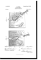
- Figure l is a perspective view of a quick-break double-throw switch constructed in accordance with my invention.
- Fig. 2 is a front elevation thereof with parts of the joint broken away to show parts beneath.
- Fig. 3 is a section through the joint, taken on line 3 3 of Fig. 2.
- Fig. 4 is a perspective view of one of the quick-break or auxiliary blades removed from the other parts of the switch.
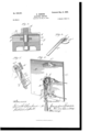
- Fig. 5 is a detail View of the joint employed in a single-throw switch where only one auxiliary blade is used.
- Fig. 6 is a perspective view of a double-throw switch having two quick-action blades Where the switch-blades swing in a plane perpendicular to the base ou which the switch is mounted.
- A indicates a base or plate of insulating material, such as slate or the like, on which the switch is mounted.
- B indicates the stationary center cli p, which is attached to the base, and C C the outer spring-clips, also secured to said base.
- F and F are the quick-action or auxiliary blades, located at opposite edges of the main blade and in the same plane therewith.
- the main and auxiliary blades are pivotally connected with the center clip B by a pivot-bolt B, and the free and outer ends of the blades engage the outer spring-clips, said spring-clips each being of slotted form and provided with spring or resilient jaws adapted to frictionally engage opposite sides of the blades in the usual manner.
- the central clip B thereof is made in the usual manner, with two parallel cheek-plates l; h', through which the pivot-bolt B passes and between which the ends of the switch-blades are located.
- the central or main blade D is provided with an aperture near its end through which the pivot-bolt B passes.
- the quick-action blades E and F which are located in the same plane with and at either edge of the main blade, are held by spring connections normally in contact with the opposite edges of the said main blade.
- Said auxiliary blades l1 and F are each provided with alaterally-projecting plate or cheek-piece E F', which overlaps the main blade and is interposed between and in contact with the same and the adjacent or inner surfaces of the cheek-pieces l) or b' ot the central clip.
- Said cheek-pieces E F of the auxiliary blades are provided with bearing-apertures c f, through which passes the bolt B.
- Said cheek-pieces may be secured to the sides of the auxiliary blades by suitable attaching means, as by rivets and brazing, or they may be made or iorged in one piece with the auxiliary blad es.
- said cheekpieccs and the blades may be cut and stamped or swaged from a single piece of metal.
- the cheelcpieces are of approximatelycircular form, so that the cheekpiece ot' each blade projects over and comes in contact with the opposite blade, as well as with the main blade.
- the cheek-pieces, made as described, being in bearing-contact with the opposite parts of the cheek-plates l) b of the center clip afford extended contact-surfaces between the clip and the blades, thereby insuring ample contact-surfaces between said parts for the passage of the current.
- auxiliaryor quick-action blades which are pivotally connected with the center clip and main blade in the manner described, are held normally in contact or parallel with the main blade by suitably-applied springs, herein shown as having the form of coiled expansion-springs G H, located at opposite sides of the blades, so as to exert an even tension or strain thereon.
- springs G and Il are connected with opposite studs l l, which project from opposite sides of the main blade, the springs G being ⁇ connected at their outer ends with studs J on opposite sides of the blade E, and the springs Il ll bein g connected with opposite studs K K on the blade F.
- the switch-blades To hold the auxiliary blades in the same plane with thel main-blade, the latter is provided with guide-pieces L L, secured to the opposite faces thereof and projecting beyond the side edges of the main blade, so as to overlap the auxiliary blades when the same are brought against the side edges of the main blade. W'hen the switch-blades thus constructed are swung to one limit oi their movement and are engaged with one of the outer spring-clips, said clip will bear upon the op-d posite sides of the main blade, as well as the auxiliary blade, which is on the side of the main blade, at which the clip engaged thereby islocated.
- the pivote@ end ol' the main, blade is provided with an extension or heel projecting beyond the pivot and having inclined or beveled edges (l (Z, located in position for contact with the inner :face or edge of the auxiliary blade when the main blade reaches an angular position with respect tothe auxiliary blade, the parts being so arranged that when the main blade has been ⁇ swung to an angle secured for the quick-break action the angular end of the main blade will strike the adjacent surface of the auxiliary blade, and thus positively swing or move the auxiliary blade until it is free from the outer spring-clip, al1'- ter which the auxiliary blade will be thrown quickly by the action ot the springs G- and Il into contact with the main blade, thereby quickly breaking the electric current.
- auxiliary blade F is still in engagement with the outer spring-clip C', but is beingl moved out of engagement therewith by pressure of the inner end or heel of the main blade, which latter is moving' toward the clip C.
- each blade is shown in Fig. 2 as provided with a projecting lug or block cf', and said lugs are arranged in the same plane with the main blade and their ends are adapted to 'form shoulders which are adapted to come in contact with each other at the same time the end ol' the main blade makes contact with that one of the auxiliary blades which is at the time held in engagement with one of the outer spring-clips.
- the lugs or blocks e f serve to make the joint very much stronger and insure a more positive action of the parts than is allorded by the pro.- jecting end of the main blade alone.
- Fig. 5 illustrates a construction which may be employed for the quick-break single-throw switch where only one auxiliary blade is used.
- the contact shoulders or lugs c' f' cannot be employed, and the main blade D is provided with a projection or heel having a beveled face or shoulder d2, adapted for contact with the inner face of the auxiliary blade E, so as to positively move the same out of contact with the spring-clip engaged by it.
- Fig. 6 illustrates my invention as applied to a double-throw switch in which the switchblades swing in a plane perpendicular to the face of the insulating base or plate A, the outer spring-clips C C in this instance being located in the same vertical plane, so that the switch-blades are-thrown or moved through an angle approximating one hundred and eighty degrees in carrying them from one outer clip to the other.
- a quick-break electric switch comprising a center clip having parallel cheek-plates, a center pivot-bolt, a main blade mounted on said pivot-bolt, and an auxiliary blade located edge to edge and in the same plane with the main blade and provided outside of the plane of said main bla-de with a cheek-piece which overlaps said main blade from edge to edge and is interposed between said main blade and one of the cheek-pieces of the center clip, said cheek-piece and auxiliary blade being provided with apertures through which said pivot-bolt passes.
- a quick-break electric switch comprising a center clip having parallel cheek-plates
- a main blade a pivot-bolt passing through the cheek-plates of the center clip and the main blade, two auxiliary blades located at opposite edges of the main blade and each provided outside of the plane of the main blade with a cheek-piece, which cheek-pieces engage at their outer faces the cheek-plates of the center clip and are separated by a space within which is located the pivoted end of the main blade.
- a quick-break electric switch comprising a center clip having parallel cheek-plates, two outer spring contact-clips, a main blade, a pivot connecting the main blade with the center clip, two auxiliary blades located at opposite edges ofthe main blade and provided each with a laterally-projecting ⁇ plate or cheelipiece which is interposed between the main blade and one of the cheek-plates of the clip and engages said pivot, said auxiliary blades being provided with opposing contact-shoulders adapted for engagement with each other for giving positive movement to said auxiliary blades for disengaging them from the said outer contact-clips.
Landscapes
- Arc-Extinguishing Devices That Are Switches (AREA)
Description
No. 648,95I. Patented May 8,1900. A. HANSGN.
ELECTRIC SWITCH.
(App 1 ation filed May 31, 1899.)
2 Sheets-Sheet l.
(No Model.)
No. 648,951. Patented may s, |900. A. HANsoN.
ELECTRIC SWITCH.
(Application filed May 31, 1899.) (No Model.) 2 Sheets-Sheei 2.
' 2 I NQ NiTED STATES PATENT' OFFICE.
AUGUSTUS I'IANSON, OF CHICAGO, ILLINOIS, ASSIGNOR OF ONE-HALF TO JOHN II. GOEHST, OF SAME PLACE.
ELECTRIC SWITCH.
SPECFICATION forming part of Letters Patent No. 648,951, dated May 8, 1900.
Application filed May 3l, 1899. Serial No. 718,810. (No model.) v
To @ZZ wiz/m, it may con/cern:
Be it known that l, AUGUSTUS HANsoN, of Chicago, in the county of Cook and State of Illinois, have invented certain new and useful Improvements in Electric Switches; and I do hereby declare that the following is a full, clear, and exact description thereof, reference being had to the accompanying drawings, and to 'the letters of reference marked thereon, which form a part of this specification.
This invention relates to novel features of construction in quick-break electric switches of the kind having a main and one or two additional or auxiliary switch-bladeshaving spring connections with each other and operating in connection with either one or two stationary spring-contact outer clips. The object of the invention is to provide an improved construction in the joints of such switches by which greater strengtlnas well as an improved electrical contact, is obtained in the parts of such joints and in other features of the switches, as will hereinafter appear.
As quick-break switches have heretofore been made the outside or quick-break blade or blades have been pivotally connected with the center or pivot clip by means of a ring which iits into segmental grooves formed in the several blades in such manner that they together constitute, in effect, an annular groove, whereby the outside blades are adapted to swinglon a central axis concentric with the center bolt or pivot'of the main blade. Such prior construction has been found objectionable, especially in double-throw switches, wherein these blades are used, for the reason, among others, that the ring referred to is liable to break, andthe blades also break at the points where the segmental grooves are located by reason of the fact thatthe metal is greatly reduced in thickness at these points. In a switch made in accordance with my invention the main switch blade is pivoted on a central pivot-pin, and the auxiliary blade or blades at one or both edges thereof is provided adjacent tov the joint with a fiat lateral projection or cheek-piece,\vl1ich en gages the pivot and overlaps the main blade and has contact both with the main blade and the side or cheek plate of the center clip,so that both the main blade and the quick-action blade or blades are pivoted directly to the said pivot, while the said laterally-extending plate 0r cheek-piece is interposed and has bearing against both the central blade and the side of the center clip, thereby giving'a broad or extended contactssurface between said central clip, the main blades, and the cheek piece or pieces, insuring ample contact-surfaces for the passage of the electric current from the central clip to boththe main and the auxiliary blades. In connec* tion with the quick-action blade thus constructed a deviccis provided at the inner ends of the main or auxiliary blades embracing parts adapted for contact with each other when the main blade is swung on the pivot in a direction away from the outer spring-clip, which engages the quick-action blade, so as to positivelymove the quick-action blade out of engagement with the spring-clip, thereby releasing the quick-action blade and allowing it to resume its position in contact with the main blade.
The invention also embraces other features of construction, as will be hereinafter described, and pointed out in the appended claims.
As shown in the drawings, Figure lis a perspective view of a quick-break double-throw switch constructed in accordance with my invention. Fig. 2 is a front elevation thereof with parts of the joint broken away to show parts beneath. Fig. 3 is a section through the joint, taken on line 3 3 of Fig. 2. Fig. 4: is a perspective view of one of the quick-break or auxiliary blades removed from the other parts of the switch. Fig. 5 is a detail View of the joint employed in a single-throw switch where only one auxiliary blade is used. Fig. 6 is a perspective view of a double-throw switch having two quick-action blades Where the switch-blades swing in a plane perpendicular to the base ou which the switch is mounted.
As shown in said drawings, A indicates a base or plate of insulating material, such as slate or the like, on which the switch is mounted.
B indicates the stationary center cli p, which is attached to the base, and C C the outer spring-clips, also secured to said base.
D indicates the center blade of the switch,
IDO
which is provided with a handle D', and F and F are the quick-action or auxiliary blades, located at opposite edges of the main blade and in the same plane therewith.
The main and auxiliary blades are pivotally connected with the center clip B by a pivot-bolt B, and the free and outer ends of the blades engage the outer spring-clips, said spring-clips each being of slotted form and provided with spring or resilient jaws adapted to frictionally engage opposite sides of the blades in the usual manner.
Now, referring to the construction ot' the center joint of the switch, the central clip B thereof is made in the usual manner, with two parallel cheek-plates l; h', through which the pivot-bolt B passes and between which the ends of the switch-blades are located. The central or main blade D is provided with an aperture near its end through which the pivot-bolt B passes. The quick-action blades E and F, which are located in the same plane with and at either edge of the main blade, are held by spring connections normally in contact with the opposite edges of the said main blade. Said auxiliary blades l1 and F are each provided with alaterally-projecting plate or cheek-piece E F', which overlaps the main blade and is interposed between and in contact with the same and the adjacent or inner surfaces of the cheek-pieces l) or b' ot the central clip. Said cheek-pieces E F of the auxiliary blades are provided with bearing-apertures c f, through which passes the bolt B. Said cheek-pieces may be secured to the sides of the auxiliary blades by suitable attaching means, as by rivets and brazing, or they may be made or iorged in one piece with the auxiliary blad es. In some instances said cheekpieccs and the blades may be cut and stamped or swaged from a single piece of metal. Preterably the cheelcpieces are of approximatelycircular form, so that the cheekpiece ot' each blade projects over and comes in contact with the opposite blade, as well as with the main blade. Obviously the cheek-pieces, made as described, being in bearing-contact with the opposite parts of the cheek-plates l) b of the center clip afford extended contact-surfaces between the clip and the blades, thereby insuring ample contact-surfaces between said parts for the passage of the current.
The auxiliaryor quick-action blades, which are pivotally connected with the center clip and main blade in the manner described, are held normally in contact or parallel with the main blade by suitably-applied springs, herein shown as having the form of coiled expansion-springs G H, located at opposite sides of the blades, so as to exert an even tension or strain thereon. Both of said springs G and Il are connected with opposite studs l l, which project from opposite sides of the main blade, the springs G being` connected at their outer ends with studs J on opposite sides of the blade E, and the springs Il ll bein g connected with opposite studs K K on the blade F. To hold the auxiliary blades in the same plane with thel main-blade, the latter is provided with guide-pieces L L, secured to the opposite faces thereof and projecting beyond the side edges of the main blade, so as to overlap the auxiliary blades when the same are brought against the side edges of the main blade. W'hen the switch-blades thus constructed are swung to one limit oi their movement and are engaged with one of the outer spring-clips, said clip will bear upon the op-d posite sides of the main blade, as well as the auxiliary blade, which is on the side of the main blade, at which the clip engaged thereby islocated. lVhen the main blade is moved by hand out of engagement with the clip at the time engaged byit, the friciional engagement of the spring-cllp with the auxiliary blade will be sufficient io prevent the release of the same, so that the quick-action blade will still remain in enga-gernen t with said clip, this position of the parts being shown at the left-hand side of Fig. 2.
In order to provide tor the release oi' the quick-action or auxiliary blades from the spring contact-clips, devices are provided as follows: The pivote@ end ol' the main, blade is provided with an extension or heel projecting beyond the pivot and having inclined or beveled edges (l (Z, located in position for contact with the inner :face or edge of the auxiliary blade when the main blade reaches an angular position with respect tothe auxiliary blade, the parts being so arranged that when the main blade has been` swung to an angle secured for the quick-break action the angular end of the main blade will strike the adjacent surface of the auxiliary blade, and thus positively swing or move the auxiliary blade until it is free from the outer spring-clip, al1'- ter which the auxiliary blade will be thrown quickly by the action ot the springs G- and Il into contact with the main blade, thereby quickly breaking the electric current. This action is clearly shown in Fig. 2, wherein the auxiliary blade F is still in engagement with the outer spring-clip C', but is beingl moved out of engagement therewith by pressure of the inner end or heel of the main blade, which latter is moving' toward the clip C. As an additional means of moving or actuating the auxiliary blades each blade is shown in Fig. 2 as provided with a projecting lug or block cf', and said lugs are arranged in the same plane with the main blade and their ends are adapted to 'form shoulders which are adapted to come in contact with each other at the same time the end ol' the main blade makes contact with that one of the auxiliary blades which is at the time held in engagement with one of the outer spring-clips. The lugs or blocks e f serve to make the joint very much stronger and insure a more positive action of the parts than is allorded by the pro.- jecting end of the main blade alone.
ICO
ITO
ISO
viously, however, when the said lugs e' f are present the main blades need not necessarily have the heel for action on the auxiliary blade to afford the releasing movement thereof referred to.
Fig. 5 illustrates a construction which may be employed for the quick-break single-throw switch where only one auxiliary blade is used. In this instance, there being only one blade, the contact shoulders or lugs c' f' cannot be employed, and the main blade D is provided with a projection or heel having a beveled face or shoulder d2, adapted for contact with the inner face of the auxiliary blade E, so as to positively move the same out of contact with the spring-clip engaged by it.
Fig. 6 illustrates my invention as applied to a double-throw switch in which the switchblades swing in a plane perpendicular to the face of the insulating base or plate A, the outer spring-clips C C in this instance being located in the same vertical plane, so that the switch-blades are-thrown or moved through an angle approximating one hundred and eighty degrees in carrying them from one outer clip to the other.
I claim as my inventionl. A quick-break electric switch comprising a center clip having parallel cheek-plates, a center pivot-bolt, a main blade mounted on said pivot-bolt, and an auxiliary blade located edge to edge and in the same plane with the main blade and provided outside of the plane of said main bla-de with a cheek-piece which overlaps said main blade from edge to edge and is interposed between said main blade and one of the cheek-pieces of the center clip, said cheek-piece and auxiliary blade being provided with apertures through which said pivot-bolt passes.
2. A quick-break electric switch comprising a center clip having parallel cheek-plates,
a main blade, a pivot-bolt passing through the cheek-plates of the center clip and the main blade, two auxiliary blades located at opposite edges of the main blade and each provided outside of the plane of the main blade with a cheek-piece, which cheek-pieces engage at their outer faces the cheek-plates of the center clip and are separated by a space within which is located the pivoted end of the main blade.
3. A quick-break electric switch comprising a center clip having parallel cheek-plates, two outer spring contact-clips, a main blade, a pivot connecting the main blade with the center clip, two auxiliary blades located at opposite edges ofthe main blade and provided each with a laterally-projecting` plate or cheelipiece which is interposed between the main blade and one of the cheek-plates of the clip and engages said pivot, said auxiliary blades being provided with opposing contact-shoulders adapted for engagement with each other for giving positive movement to said auxiliary blades for disengaging them from the said outer contact-clips.
In testimony that I claim the foregoing as my invention I afiix my signatn re, in presence of two witnesses, this 29th day of May, A. l). 1899.
AUGUSTUSl HANSON.
lVitnesses:
WILLIAM L. HALL, GERTRUDE BRYcE.
Priority Applications (1)
| Application Number | Priority Date | Filing Date | Title |
|---|---|---|---|
| US71881099A US648951A (en) | 1899-05-31 | 1899-05-31 | Electric switch. |
Applications Claiming Priority (1)
| Application Number | Priority Date | Filing Date | Title |
|---|---|---|---|
| US71881099A US648951A (en) | 1899-05-31 | 1899-05-31 | Electric switch. |
Publications (1)
| Publication Number | Publication Date |
|---|---|
| US648951A true US648951A (en) | 1900-05-08 |
Family
ID=2717523
Family Applications (1)
| Application Number | Title | Priority Date | Filing Date |
|---|---|---|---|
| US71881099A Expired - Lifetime US648951A (en) | 1899-05-31 | 1899-05-31 | Electric switch. |
Country Status (1)
| Country | Link |
|---|---|
| US (1) | US648951A (en) |
Cited By (2)
| Publication number | Priority date | Publication date | Assignee | Title |
|---|---|---|---|---|
| US2436750A (en) * | 1944-08-17 | 1948-02-24 | Grayhill | Rotary selector switch |
| US4090046A (en) * | 1977-06-20 | 1978-05-16 | A.B.C. Auto Alarms, Inc. | Key operated switch for automobile alarm or the like |
-
1899
- 1899-05-31 US US71881099A patent/US648951A/en not_active Expired - Lifetime
Cited By (2)
| Publication number | Priority date | Publication date | Assignee | Title |
|---|---|---|---|---|
| US2436750A (en) * | 1944-08-17 | 1948-02-24 | Grayhill | Rotary selector switch |
| US4090046A (en) * | 1977-06-20 | 1978-05-16 | A.B.C. Auto Alarms, Inc. | Key operated switch for automobile alarm or the like |
Similar Documents
| Publication | Publication Date | Title |
|---|---|---|
| US942043A (en) | Shears. | |
| US633771A (en) | Switch for electric circuits. | |
| US677340A (en) | Electric switch. | |
| US1093793A (en) | Electric switch. | |
| US1486744A (en) | Electric switch | |
| US500184A (en) | Bolt-cutter | |
| US1509615A (en) | Multiple-blade knife switch | |
| US489553A (en) | George baehr | |
| US1236133A (en) | Electric switch. | |
| US481200A (en) | Shears | |
| US615347A (en) | Island | |
| US1838239A (en) | Electric switch of the tumbler type | |
| US445146A (en) | Electric switch | |
| US750993A (en) | Electric switch | |
| US398510A (en) | Electric switch | |
| US1950556A (en) | Electric switch construction | |
| US1906505A (en) | Switch | |
| US537665A (en) | Electric switch | |
| US1080563A (en) | Electric switch. | |
| US1543495A (en) | Oil circuit breaker | |
| US755743A (en) | Removable contact-finger tip. | |
| US1848733A (en) | oe albany | |
| US617275A (en) | William f | |
| US471760A (en) | Electric switch | |
| US335269A (en) | Electrical switch |