US6489266B1 - Image-receiving sheet - Google Patents
Image-receiving sheet Download PDFInfo
- Publication number
- US6489266B1 US6489266B1 US09/124,168 US12416898A US6489266B1 US 6489266 B1 US6489266 B1 US 6489266B1 US 12416898 A US12416898 A US 12416898A US 6489266 B1 US6489266 B1 US 6489266B1
- Authority
- US
- United States
- Prior art keywords
- convexo
- layer
- concave pattern
- receiving sheet
- image
- Prior art date
- Legal status (The legal status is an assumption and is not a legal conclusion. Google has not performed a legal analysis and makes no representation as to the accuracy of the status listed.)
- Expired - Fee Related
Links
- 239000010410 layer Substances 0.000 claims abstract description 259
- 239000000758 substrate Substances 0.000 claims abstract description 103
- 239000012790 adhesive layer Substances 0.000 claims abstract description 22
- 239000012780 transparent material Substances 0.000 claims description 6
- 239000010408 film Substances 0.000 description 36
- 238000000034 method Methods 0.000 description 34
- 229920005989 resin Polymers 0.000 description 32
- 239000011347 resin Substances 0.000 description 32
- 230000015572 biosynthetic process Effects 0.000 description 29
- 239000000463 material Substances 0.000 description 18
- 239000000123 paper Substances 0.000 description 18
- -1 polyethylene terephthalate Polymers 0.000 description 18
- 239000011248 coating agent Substances 0.000 description 17
- 238000000576 coating method Methods 0.000 description 17
- 229910052751 metal Inorganic materials 0.000 description 14
- 239000002184 metal Substances 0.000 description 14
- 229920002545 silicone oil Polymers 0.000 description 14
- 239000010409 thin film Substances 0.000 description 11
- 239000000975 dye Substances 0.000 description 10
- 229920001577 copolymer Polymers 0.000 description 9
- 238000000859 sublimation Methods 0.000 description 9
- 230000008022 sublimation Effects 0.000 description 9
- 230000000694 effects Effects 0.000 description 8
- 239000000203 mixture Substances 0.000 description 8
- NIXOWILDQLNWCW-UHFFFAOYSA-M Acrylate Chemical compound [O-]C(=O)C=C NIXOWILDQLNWCW-UHFFFAOYSA-M 0.000 description 7
- 239000007788 liquid Substances 0.000 description 7
- ZWEHNKRNPOVVGH-UHFFFAOYSA-N 2-Butanone Chemical compound CCC(C)=O ZWEHNKRNPOVVGH-UHFFFAOYSA-N 0.000 description 6
- 239000004925 Acrylic resin Substances 0.000 description 6
- 229920000178 Acrylic resin Polymers 0.000 description 6
- YXFVVABEGXRONW-UHFFFAOYSA-N Toluene Chemical compound CC1=CC=CC=C1 YXFVVABEGXRONW-UHFFFAOYSA-N 0.000 description 6
- 230000003287 optical effect Effects 0.000 description 6
- 229920000139 polyethylene terephthalate Polymers 0.000 description 6
- 239000005020 polyethylene terephthalate Substances 0.000 description 6
- 229920002554 vinyl polymer Polymers 0.000 description 6
- 239000004743 Polypropylene Substances 0.000 description 5
- 239000004793 Polystyrene Substances 0.000 description 5
- 239000002216 antistatic agent Substances 0.000 description 5
- 239000003795 chemical substances by application Substances 0.000 description 5
- 150000002739 metals Chemical class 0.000 description 5
- 229920001155 polypropylene Polymers 0.000 description 5
- 229920002223 polystyrene Polymers 0.000 description 5
- PPBRXRYQALVLMV-UHFFFAOYSA-N Styrene Chemical compound C=CC1=CC=CC=C1 PPBRXRYQALVLMV-UHFFFAOYSA-N 0.000 description 4
- BZHJMEDXRYGGRV-UHFFFAOYSA-N Vinyl chloride Chemical compound ClC=C BZHJMEDXRYGGRV-UHFFFAOYSA-N 0.000 description 4
- 229920001971 elastomer Polymers 0.000 description 4
- 239000000945 filler Substances 0.000 description 4
- 230000004927 fusion Effects 0.000 description 4
- 238000004519 manufacturing process Methods 0.000 description 4
- 239000002985 plastic film Substances 0.000 description 4
- 229920006255 plastic film Polymers 0.000 description 4
- 229920001225 polyester resin Polymers 0.000 description 4
- 239000004645 polyester resin Substances 0.000 description 4
- 239000004800 polyvinyl chloride Substances 0.000 description 4
- 229920000915 polyvinyl chloride Polymers 0.000 description 4
- 230000003405 preventing effect Effects 0.000 description 4
- 239000005060 rubber Substances 0.000 description 4
- 238000007740 vapor deposition Methods 0.000 description 4
- 125000000391 vinyl group Chemical group [H]C([*])=C([H])[H] 0.000 description 4
- 230000000007 visual effect Effects 0.000 description 4
- 239000004593 Epoxy Substances 0.000 description 3
- XEKOWRVHYACXOJ-UHFFFAOYSA-N Ethyl acetate Chemical compound CCOC(C)=O XEKOWRVHYACXOJ-UHFFFAOYSA-N 0.000 description 3
- 229920000877 Melamine resin Polymers 0.000 description 3
- 239000004372 Polyvinyl alcohol Substances 0.000 description 3
- 230000004075 alteration Effects 0.000 description 3
- 229910052782 aluminium Inorganic materials 0.000 description 3
- 238000001035 drying Methods 0.000 description 3
- 239000000025 natural resin Substances 0.000 description 3
- 229920006122 polyamide resin Polymers 0.000 description 3
- 229920000642 polymer Polymers 0.000 description 3
- 229920000098 polyolefin Polymers 0.000 description 3
- 229920005672 polyolefin resin Polymers 0.000 description 3
- 229920002451 polyvinyl alcohol Polymers 0.000 description 3
- 239000007787 solid Substances 0.000 description 3
- KLZUFWVZNOTSEM-UHFFFAOYSA-K Aluminium flouride Chemical compound F[Al](F)F KLZUFWVZNOTSEM-UHFFFAOYSA-K 0.000 description 2
- KAKZBPTYRLMSJV-UHFFFAOYSA-N Butadiene Chemical compound C=CC=C KAKZBPTYRLMSJV-UHFFFAOYSA-N 0.000 description 2
- VGGSQFUCUMXWEO-UHFFFAOYSA-N Ethene Chemical compound C=C VGGSQFUCUMXWEO-UHFFFAOYSA-N 0.000 description 2
- 239000001856 Ethyl cellulose Substances 0.000 description 2
- ZZSNKZQZMQGXPY-UHFFFAOYSA-N Ethyl cellulose Chemical compound CCOCC1OC(OC)C(OCC)C(OCC)C1OC1C(O)C(O)C(OC)C(CO)O1 ZZSNKZQZMQGXPY-UHFFFAOYSA-N 0.000 description 2
- 239000005977 Ethylene Substances 0.000 description 2
- 239000005062 Polybutadiene Substances 0.000 description 2
- 229920001328 Polyvinylidene chloride Polymers 0.000 description 2
- OFOBLEOULBTSOW-UHFFFAOYSA-N Propanedioic acid Natural products OC(=O)CC(O)=O OFOBLEOULBTSOW-UHFFFAOYSA-N 0.000 description 2
- VYPSYNLAJGMNEJ-UHFFFAOYSA-N Silicium dioxide Chemical compound O=[Si]=O VYPSYNLAJGMNEJ-UHFFFAOYSA-N 0.000 description 2
- 229920002472 Starch Polymers 0.000 description 2
- NIXOWILDQLNWCW-UHFFFAOYSA-N acrylic acid group Chemical group C(C=C)(=O)O NIXOWILDQLNWCW-UHFFFAOYSA-N 0.000 description 2
- 239000000853 adhesive Substances 0.000 description 2
- 150000001336 alkenes Chemical class 0.000 description 2
- XAGFODPZIPBFFR-UHFFFAOYSA-N aluminium Chemical compound [Al] XAGFODPZIPBFFR-UHFFFAOYSA-N 0.000 description 2
- TZCXTZWJZNENPQ-UHFFFAOYSA-L barium sulfate Chemical compound [Ba+2].[O-]S([O-])(=O)=O TZCXTZWJZNENPQ-UHFFFAOYSA-L 0.000 description 2
- WMWLMWRWZQELOS-UHFFFAOYSA-N bismuth(iii) oxide Chemical compound O=[Bi]O[Bi]=O WMWLMWRWZQELOS-UHFFFAOYSA-N 0.000 description 2
- MTAZNLWOLGHBHU-UHFFFAOYSA-N butadiene-styrene rubber Chemical compound C=CC=C.C=CC1=CC=CC=C1 MTAZNLWOLGHBHU-UHFFFAOYSA-N 0.000 description 2
- 229910052793 cadmium Inorganic materials 0.000 description 2
- 239000003054 catalyst Substances 0.000 description 2
- 150000001875 compounds Chemical class 0.000 description 2
- JHIVVAPYMSGYDF-UHFFFAOYSA-N cyclohexanone Chemical compound O=C1CCCCC1 JHIVVAPYMSGYDF-UHFFFAOYSA-N 0.000 description 2
- 230000007423 decrease Effects 0.000 description 2
- 238000000609 electron-beam lithography Methods 0.000 description 2
- 238000005516 engineering process Methods 0.000 description 2
- 239000003822 epoxy resin Substances 0.000 description 2
- 235000019325 ethyl cellulose Nutrition 0.000 description 2
- 229920001249 ethyl cellulose Polymers 0.000 description 2
- 238000010438 heat treatment Methods 0.000 description 2
- 229910052738 indium Inorganic materials 0.000 description 2
- 229920000554 ionomer Polymers 0.000 description 2
- VZCYOOQTPOCHFL-UPHRSURJSA-N maleic acid Chemical compound OC(=O)\C=C/C(O)=O VZCYOOQTPOCHFL-UPHRSURJSA-N 0.000 description 2
- 239000011976 maleic acid Substances 0.000 description 2
- JDSHMPZPIAZGSV-UHFFFAOYSA-N melamine Chemical compound NC1=NC(N)=NC(N)=N1 JDSHMPZPIAZGSV-UHFFFAOYSA-N 0.000 description 2
- 150000004767 nitrides Chemical class 0.000 description 2
- JRZJOMJEPLMPRA-UHFFFAOYSA-N olefin Natural products CCCCCCCC=C JRZJOMJEPLMPRA-UHFFFAOYSA-N 0.000 description 2
- 229920003229 poly(methyl methacrylate) Polymers 0.000 description 2
- 229920002857 polybutadiene Polymers 0.000 description 2
- 229920000647 polyepoxide Polymers 0.000 description 2
- 229920000728 polyester Polymers 0.000 description 2
- 239000004848 polyfunctional curative Substances 0.000 description 2
- 239000004926 polymethyl methacrylate Substances 0.000 description 2
- 229920001296 polysiloxane Polymers 0.000 description 2
- 229920005749 polyurethane resin Polymers 0.000 description 2
- 229920002689 polyvinyl acetate Polymers 0.000 description 2
- 239000011118 polyvinyl acetate Substances 0.000 description 2
- 239000005033 polyvinylidene chloride Substances 0.000 description 2
- 230000002265 prevention Effects 0.000 description 2
- 229910052709 silver Inorganic materials 0.000 description 2
- 239000008107 starch Substances 0.000 description 2
- 235000019698 starch Nutrition 0.000 description 2
- 239000004094 surface-active agent Substances 0.000 description 2
- 229920003002 synthetic resin Polymers 0.000 description 2
- 239000000057 synthetic resin Substances 0.000 description 2
- 229920005992 thermoplastic resin Polymers 0.000 description 2
- 229920001187 thermosetting polymer Polymers 0.000 description 2
- 229910052718 tin Inorganic materials 0.000 description 2
- VZCYOOQTPOCHFL-UHFFFAOYSA-N trans-butenedioic acid Natural products OC(=O)C=CC(O)=O VZCYOOQTPOCHFL-UHFFFAOYSA-N 0.000 description 2
- XLYOFNOQVPJJNP-UHFFFAOYSA-N water Substances O XLYOFNOQVPJJNP-UHFFFAOYSA-N 0.000 description 2
- 229920003169 water-soluble polymer Polymers 0.000 description 2
- 229910052725 zinc Inorganic materials 0.000 description 2
- LNAZSHAWQACDHT-XIYTZBAFSA-N (2r,3r,4s,5r,6s)-4,5-dimethoxy-2-(methoxymethyl)-3-[(2s,3r,4s,5r,6r)-3,4,5-trimethoxy-6-(methoxymethyl)oxan-2-yl]oxy-6-[(2r,3r,4s,5r,6r)-4,5,6-trimethoxy-2-(methoxymethyl)oxan-3-yl]oxyoxane Chemical compound CO[C@@H]1[C@@H](OC)[C@H](OC)[C@@H](COC)O[C@H]1O[C@H]1[C@H](OC)[C@@H](OC)[C@H](O[C@H]2[C@@H]([C@@H](OC)[C@H](OC)O[C@@H]2COC)OC)O[C@@H]1COC LNAZSHAWQACDHT-XIYTZBAFSA-N 0.000 description 1
- YTLYLLTVENPWFT-UPHRSURJSA-N (Z)-3-aminoacrylic acid Chemical compound N\C=C/C(O)=O YTLYLLTVENPWFT-UPHRSURJSA-N 0.000 description 1
- JYEUMXHLPRZUAT-UHFFFAOYSA-N 1,2,3-triazine Chemical compound C1=CN=NN=C1 JYEUMXHLPRZUAT-UHFFFAOYSA-N 0.000 description 1
- IXPNQXFRVYWDDI-UHFFFAOYSA-N 1-methyl-2,4-dioxo-1,3-diazinane-5-carboximidamide Chemical compound CN1CC(C(N)=N)C(=O)NC1=O IXPNQXFRVYWDDI-UHFFFAOYSA-N 0.000 description 1
- SMZOUWXMTYCWNB-UHFFFAOYSA-N 2-(2-methoxy-5-methylphenyl)ethanamine Chemical compound COC1=CC=C(C)C=C1CCN SMZOUWXMTYCWNB-UHFFFAOYSA-N 0.000 description 1
- RSWGJHLUYNHPMX-UHFFFAOYSA-N Abietic-Saeure Natural products C12CCC(C(C)C)=CC2=CCC2C1(C)CCCC2(C)C(O)=O RSWGJHLUYNHPMX-UHFFFAOYSA-N 0.000 description 1
- NLHHRLWOUZZQLW-UHFFFAOYSA-N Acrylonitrile Chemical compound C=CC#N NLHHRLWOUZZQLW-UHFFFAOYSA-N 0.000 description 1
- 229920002799 BoPET Polymers 0.000 description 1
- 229920002134 Carboxymethyl cellulose Polymers 0.000 description 1
- 229920008347 Cellulose acetate propionate Polymers 0.000 description 1
- 229920001747 Cellulose diacetate Polymers 0.000 description 1
- 239000004375 Dextrin Substances 0.000 description 1
- 229920001353 Dextrin Polymers 0.000 description 1
- JOYRKODLDBILNP-UHFFFAOYSA-N Ethyl urethane Chemical compound CCOC(N)=O JOYRKODLDBILNP-UHFFFAOYSA-N 0.000 description 1
- 239000004716 Ethylene/acrylic acid copolymer Substances 0.000 description 1
- YCKRFDGAMUMZLT-UHFFFAOYSA-N Fluorine atom Chemical compound [F] YCKRFDGAMUMZLT-UHFFFAOYSA-N 0.000 description 1
- 229920000084 Gum arabic Polymers 0.000 description 1
- 239000004354 Hydroxyethyl cellulose Substances 0.000 description 1
- 239000004640 Melamine resin Substances 0.000 description 1
- 229920001890 Novodur Polymers 0.000 description 1
- 229910019142 PO4 Inorganic materials 0.000 description 1
- 239000002202 Polyethylene glycol Substances 0.000 description 1
- 229920002873 Polyethylenimine Polymers 0.000 description 1
- 229920002367 Polyisobutene Polymers 0.000 description 1
- 239000004721 Polyphenylene oxide Substances 0.000 description 1
- KHPCPRHQVVSZAH-HUOMCSJISA-N Rosin Natural products O(C/C=C/c1ccccc1)[C@H]1[C@H](O)[C@@H](O)[C@@H](O)[C@@H](CO)O1 KHPCPRHQVVSZAH-HUOMCSJISA-N 0.000 description 1
- 241000978776 Senegalia senegal Species 0.000 description 1
- BQCADISMDOOEFD-UHFFFAOYSA-N Silver Chemical compound [Ag] BQCADISMDOOEFD-UHFFFAOYSA-N 0.000 description 1
- GWEVSGVZZGPLCZ-UHFFFAOYSA-N Titan oxide Chemical compound O=[Ti]=O GWEVSGVZZGPLCZ-UHFFFAOYSA-N 0.000 description 1
- 238000010521 absorption reaction Methods 0.000 description 1
- 235000010489 acacia gum Nutrition 0.000 description 1
- 239000000205 acacia gum Substances 0.000 description 1
- DHKHKXVYLBGOIT-UHFFFAOYSA-N acetaldehyde Diethyl Acetal Natural products CCOC(C)OCC DHKHKXVYLBGOIT-UHFFFAOYSA-N 0.000 description 1
- 150000001241 acetals Chemical class 0.000 description 1
- 229920006243 acrylic copolymer Polymers 0.000 description 1
- 239000000654 additive Substances 0.000 description 1
- 230000000996 additive effect Effects 0.000 description 1
- 230000001464 adherent effect Effects 0.000 description 1
- 230000001070 adhesive effect Effects 0.000 description 1
- XYLMUPLGERFSHI-UHFFFAOYSA-N alpha-Methylstyrene Chemical compound CC(=C)C1=CC=CC=C1 XYLMUPLGERFSHI-UHFFFAOYSA-N 0.000 description 1
- 125000000129 anionic group Chemical group 0.000 description 1
- 239000011324 bead Substances 0.000 description 1
- 229920006378 biaxially oriented polypropylene Polymers 0.000 description 1
- 239000011127 biaxially oriented polypropylene Substances 0.000 description 1
- 239000011230 binding agent Substances 0.000 description 1
- 229920005549 butyl rubber Polymers 0.000 description 1
- 239000001768 carboxy methyl cellulose Substances 0.000 description 1
- 235000010948 carboxy methyl cellulose Nutrition 0.000 description 1
- 229920003090 carboxymethyl hydroxyethyl cellulose Polymers 0.000 description 1
- 239000008112 carboxymethyl-cellulose Substances 0.000 description 1
- 239000005018 casein Substances 0.000 description 1
- BECPQYXYKAMYBN-UHFFFAOYSA-N casein, tech. Chemical compound NCCCCC(C(O)=O)N=C(O)C(CC(O)=O)N=C(O)C(CCC(O)=N)N=C(O)C(CC(C)C)N=C(O)C(CCC(O)=O)N=C(O)C(CC(O)=O)N=C(O)C(CCC(O)=O)N=C(O)C(C(C)O)N=C(O)C(CCC(O)=N)N=C(O)C(CCC(O)=N)N=C(O)C(CCC(O)=N)N=C(O)C(CCC(O)=O)N=C(O)C(CCC(O)=O)N=C(O)C(COP(O)(O)=O)N=C(O)C(CCC(O)=N)N=C(O)C(N)CC1=CC=CC=C1 BECPQYXYKAMYBN-UHFFFAOYSA-N 0.000 description 1
- 235000021240 caseins Nutrition 0.000 description 1
- 125000002091 cationic group Chemical group 0.000 description 1
- 229920006319 cationized starch Polymers 0.000 description 1
- 239000001913 cellulose Substances 0.000 description 1
- 229920002678 cellulose Polymers 0.000 description 1
- 229910052802 copper Inorganic materials 0.000 description 1
- 235000019425 dextrin Nutrition 0.000 description 1
- 235000014113 dietary fatty acids Nutrition 0.000 description 1
- 150000002148 esters Chemical class 0.000 description 1
- 239000000194 fatty acid Substances 0.000 description 1
- 229930195729 fatty acid Natural products 0.000 description 1
- 229910052731 fluorine Inorganic materials 0.000 description 1
- 239000011737 fluorine Substances 0.000 description 1
- 235000010985 glycerol esters of wood rosin Nutrition 0.000 description 1
- 150000004820 halides Chemical class 0.000 description 1
- LNEPOXFFQSENCJ-UHFFFAOYSA-N haloperidol Chemical compound C1CC(O)(C=2C=CC(Cl)=CC=2)CCN1CCCC(=O)C1=CC=C(F)C=C1 LNEPOXFFQSENCJ-UHFFFAOYSA-N 0.000 description 1
- 235000019447 hydroxyethyl cellulose Nutrition 0.000 description 1
- 238000007733 ion plating Methods 0.000 description 1
- 229910052742 iron Inorganic materials 0.000 description 1
- 230000001678 irradiating effect Effects 0.000 description 1
- 238000002372 labelling Methods 0.000 description 1
- 238000010030 laminating Methods 0.000 description 1
- 238000003475 lamination Methods 0.000 description 1
- 229910052745 lead Inorganic materials 0.000 description 1
- HWSZZLVAJGOAAY-UHFFFAOYSA-L lead(II) chloride Chemical compound Cl[Pb]Cl HWSZZLVAJGOAAY-UHFFFAOYSA-L 0.000 description 1
- 229910001635 magnesium fluoride Inorganic materials 0.000 description 1
- 150000002689 maleic acids Chemical class 0.000 description 1
- 229920000609 methyl cellulose Polymers 0.000 description 1
- 239000001923 methylcellulose Substances 0.000 description 1
- 235000010981 methylcellulose Nutrition 0.000 description 1
- 238000002156 mixing Methods 0.000 description 1
- 239000000178 monomer Substances 0.000 description 1
- AJDUTMFFZHIJEM-UHFFFAOYSA-N n-(9,10-dioxoanthracen-1-yl)-4-[4-[[4-[4-[(9,10-dioxoanthracen-1-yl)carbamoyl]phenyl]phenyl]diazenyl]phenyl]benzamide Chemical compound O=C1C2=CC=CC=C2C(=O)C2=C1C=CC=C2NC(=O)C(C=C1)=CC=C1C(C=C1)=CC=C1N=NC(C=C1)=CC=C1C(C=C1)=CC=C1C(=O)NC1=CC=CC2=C1C(=O)C1=CC=CC=C1C2=O AJDUTMFFZHIJEM-UHFFFAOYSA-N 0.000 description 1
- 235000013808 oxidized starch Nutrition 0.000 description 1
- 239000001254 oxidized starch Substances 0.000 description 1
- 239000002245 particle Substances 0.000 description 1
- 239000003208 petroleum Substances 0.000 description 1
- 235000021317 phosphate Nutrition 0.000 description 1
- 238000007747 plating Methods 0.000 description 1
- 229920001495 poly(sodium acrylate) polymer Polymers 0.000 description 1
- 229920002037 poly(vinyl butyral) polymer Polymers 0.000 description 1
- 229920002401 polyacrylamide Polymers 0.000 description 1
- 229920000058 polyacrylate Polymers 0.000 description 1
- 229920000768 polyamine Chemical class 0.000 description 1
- 229920001707 polybutylene terephthalate Polymers 0.000 description 1
- 239000004417 polycarbonate Substances 0.000 description 1
- 229920000515 polycarbonate Polymers 0.000 description 1
- 229920006289 polycarbonate film Polymers 0.000 description 1
- 229920005668 polycarbonate resin Polymers 0.000 description 1
- 239000004431 polycarbonate resin Substances 0.000 description 1
- 229920006267 polyester film Polymers 0.000 description 1
- 229920000570 polyether Polymers 0.000 description 1
- 229920000120 polyethyl acrylate Polymers 0.000 description 1
- 229920001223 polyethylene glycol Polymers 0.000 description 1
- 229920013716 polyethylene resin Polymers 0.000 description 1
- 229920000193 polymethacrylate Polymers 0.000 description 1
- 229920005862 polyol Polymers 0.000 description 1
- 150000003077 polyols Chemical class 0.000 description 1
- 229920001451 polypropylene glycol Polymers 0.000 description 1
- 229920005990 polystyrene resin Polymers 0.000 description 1
- 229920001343 polytetrafluoroethylene Polymers 0.000 description 1
- 239000004810 polytetrafluoroethylene Substances 0.000 description 1
- 229920002635 polyurethane Polymers 0.000 description 1
- 239000004814 polyurethane Substances 0.000 description 1
- 229920001289 polyvinyl ether Polymers 0.000 description 1
- 229920000036 polyvinylpyrrolidone Polymers 0.000 description 1
- 239000001267 polyvinylpyrrolidone Substances 0.000 description 1
- 235000013855 polyvinylpyrrolidone Nutrition 0.000 description 1
- 238000003825 pressing Methods 0.000 description 1
- QQONPFPTGQHPMA-UHFFFAOYSA-N propylene Natural products CC=C QQONPFPTGQHPMA-UHFFFAOYSA-N 0.000 description 1
- 125000004805 propylene group Chemical group [H]C([H])([H])C([H])([*:1])C([H])([H])[*:2] 0.000 description 1
- 150000003242 quaternary ammonium salts Chemical class 0.000 description 1
- 238000010526 radical polymerization reaction Methods 0.000 description 1
- 238000012216 screening Methods 0.000 description 1
- 229910052711 selenium Inorganic materials 0.000 description 1
- 230000035945 sensitivity Effects 0.000 description 1
- 239000000377 silicon dioxide Substances 0.000 description 1
- 239000004332 silver Substances 0.000 description 1
- 239000002356 single layer Substances 0.000 description 1
- 235000010413 sodium alginate Nutrition 0.000 description 1
- 239000000661 sodium alginate Substances 0.000 description 1
- 229940005550 sodium alginate Drugs 0.000 description 1
- NNMHYFLPFNGQFZ-UHFFFAOYSA-M sodium polyacrylate Chemical compound [Na+].[O-]C(=O)C=C NNMHYFLPFNGQFZ-UHFFFAOYSA-M 0.000 description 1
- 239000002904 solvent Substances 0.000 description 1
- 238000004544 sputter deposition Methods 0.000 description 1
- 229920003051 synthetic elastomer Polymers 0.000 description 1
- 229920001059 synthetic polymer Polymers 0.000 description 1
- 239000005061 synthetic rubber Substances 0.000 description 1
- OGIDPMRJRNCKJF-UHFFFAOYSA-N titanium oxide Inorganic materials [Ti]=O OGIDPMRJRNCKJF-UHFFFAOYSA-N 0.000 description 1
- KHPCPRHQVVSZAH-UHFFFAOYSA-N trans-cinnamyl beta-D-glucopyranoside Natural products OC1C(O)C(O)C(CO)OC1OCC=CC1=CC=CC=C1 KHPCPRHQVVSZAH-UHFFFAOYSA-N 0.000 description 1
- 229920006305 unsaturated polyester Polymers 0.000 description 1
- 239000001043 yellow dye Substances 0.000 description 1
Images

Classifications
-
- B—PERFORMING OPERATIONS; TRANSPORTING
- B41—PRINTING; LINING MACHINES; TYPEWRITERS; STAMPS
- B41M—PRINTING, DUPLICATING, MARKING, OR COPYING PROCESSES; COLOUR PRINTING
- B41M5/00—Duplicating or marking methods; Sheet materials for use therein
- B41M5/50—Recording sheets characterised by the coating used to improve ink, dye or pigment receptivity, e.g. for ink-jet or thermal dye transfer recording
- B41M5/502—Recording sheets characterised by the coating used to improve ink, dye or pigment receptivity, e.g. for ink-jet or thermal dye transfer recording characterised by structural details, e.g. multilayer materials
-
- G—PHYSICS
- G03—PHOTOGRAPHY; CINEMATOGRAPHY; ANALOGOUS TECHNIQUES USING WAVES OTHER THAN OPTICAL WAVES; ELECTROGRAPHY; HOLOGRAPHY
- G03H—HOLOGRAPHIC PROCESSES OR APPARATUS
- G03H1/00—Holographic processes or apparatus using light, infrared or ultraviolet waves for obtaining holograms or for obtaining an image from them; Details peculiar thereto
- G03H1/02—Details of features involved during the holographic process; Replication of holograms without interference recording
- G03H1/0252—Laminate comprising a hologram layer
-
- G—PHYSICS
- G03—PHOTOGRAPHY; CINEMATOGRAPHY; ANALOGOUS TECHNIQUES USING WAVES OTHER THAN OPTICAL WAVES; ELECTROGRAPHY; HOLOGRAPHY
- G03H—HOLOGRAPHIC PROCESSES OR APPARATUS
- G03H1/00—Holographic processes or apparatus using light, infrared or ultraviolet waves for obtaining holograms or for obtaining an image from them; Details peculiar thereto
- G03H1/02—Details of features involved during the holographic process; Replication of holograms without interference recording
- G03H1/024—Hologram nature or properties
- G03H1/0244—Surface relief holograms
-
- G—PHYSICS
- G03—PHOTOGRAPHY; CINEMATOGRAPHY; ANALOGOUS TECHNIQUES USING WAVES OTHER THAN OPTICAL WAVES; ELECTROGRAPHY; HOLOGRAPHY
- G03H—HOLOGRAPHIC PROCESSES OR APPARATUS
- G03H1/00—Holographic processes or apparatus using light, infrared or ultraviolet waves for obtaining holograms or for obtaining an image from them; Details peculiar thereto
- G03H1/02—Details of features involved during the holographic process; Replication of holograms without interference recording
- G03H1/024—Hologram nature or properties
- G03H1/0248—Volume holograms
-
- G—PHYSICS
- G03—PHOTOGRAPHY; CINEMATOGRAPHY; ANALOGOUS TECHNIQUES USING WAVES OTHER THAN OPTICAL WAVES; ELECTROGRAPHY; HOLOGRAPHY
- G03H—HOLOGRAPHIC PROCESSES OR APPARATUS
- G03H2250/00—Laminate comprising a hologram layer
- G03H2250/10—Laminate comprising a hologram layer arranged to be transferred onto a carrier body
-
- G—PHYSICS
- G03—PHOTOGRAPHY; CINEMATOGRAPHY; ANALOGOUS TECHNIQUES USING WAVES OTHER THAN OPTICAL WAVES; ELECTROGRAPHY; HOLOGRAPHY
- G03H—HOLOGRAPHIC PROCESSES OR APPARATUS
- G03H2250/00—Laminate comprising a hologram layer
- G03H2250/12—Special arrangement of layers
-
- G—PHYSICS
- G03—PHOTOGRAPHY; CINEMATOGRAPHY; ANALOGOUS TECHNIQUES USING WAVES OTHER THAN OPTICAL WAVES; ELECTROGRAPHY; HOLOGRAPHY
- G03H—HOLOGRAPHIC PROCESSES OR APPARATUS
- G03H2250/00—Laminate comprising a hologram layer
- G03H2250/36—Conform enhancement layer
-
- G—PHYSICS
- G03—PHOTOGRAPHY; CINEMATOGRAPHY; ANALOGOUS TECHNIQUES USING WAVES OTHER THAN OPTICAL WAVES; ELECTROGRAPHY; HOLOGRAPHY
- G03H—HOLOGRAPHIC PROCESSES OR APPARATUS
- G03H2250/00—Laminate comprising a hologram layer
- G03H2250/40—Printed information overlapped with the hologram
-
- G—PHYSICS
- G03—PHOTOGRAPHY; CINEMATOGRAPHY; ANALOGOUS TECHNIQUES USING WAVES OTHER THAN OPTICAL WAVES; ELECTROGRAPHY; HOLOGRAPHY
- G03H—HOLOGRAPHIC PROCESSES OR APPARATUS
- G03H2270/00—Substrate bearing the hologram
- G03H2270/10—Composition
- G03H2270/12—Fibrous, e.g. paper, textile
Definitions
- the present invention relates to an image-receiving sheet. More specifically, the present invention relates to an image-receiving sheet which can form a high-quality image and which provides optical information by reflected light.
- a printer based on such method as a sublimation type thermal transfer method, a heat fusion type transfer method, or an ink-jet method is used for the output print of a computer or a word processor.
- a printer based on such method as a sublimation type thermal transfer method, a heat fusion type transfer method, or an ink-jet method is used for the output print of a computer or a word processor.
- the image formation according to the above-mentioned methods is performed by using a sheet provided with a receptor layer designed to carry a sublimation dye, a heat fusible ink, an ink, or the like.
- this image-receiving sheet is a white sheet or a transparent sheet.
- the image-receiving sheet is provided with a hologram by transfer, lamination or the like for such purpose as prevention of counterfeiting, prevention of alteration, or for addition of a special effect to the image.
- the formation of the hologram on the receptor layer after image formation thereon has been associated with the following problems. That is, it is necessary to use a special printer which is provided with both an image forming step and a hologram forming step. Alternatively, it is necessary to use a special device for the hologram formation separately from a printer for the image formation. Because of this, the image formation becomes less easy and an increase in cost is unavoidable. Further, the hologram formation by, for example, use of a thin film of metallic vapor deposition must be avoided because the film hides the image already formed in the receptor layer, and therefore a significant restriction has been imposed on the hologram formation.
- the object of the present invention is to provide an image-receiving sheet which can produce a high-quality image based on private or specific information and which provides optical information by reflected light.
- the image-receiving sheet of the present invention comprises a substrate sheet, a reflection layer disposed on at least one surface side of the substrate sheet so as to be laid on at least one area thereof, and a receptor layer disposed on at least one surface side of the substrate, wherein said reflection layer has at least one area provided with a convexo-concave pattern, the area provided with the convexo-concave pattern of the reflection layer being extended within an area provided with the receptor layer.
- the image-receiving sheet of the present invention makes it possible to form an image in the receptor layer by a thermal transfer method, an ink-jet method, or the like, it is possible to form a high-quality image based on private information.
- the image-receiving sheet of the present invention the light reflected by the convexo-concave pattern of the reflection layer can be recognized through the receptor layer. Because of this, a special effect can be imparted to the image formed in the receptor layer. Since these effects can be obtained by use of an image forming printer which is based on a thermal transfer method, an ink-jet method, or the like and which is not provided with the hologram forming step, the image formation is easy and cost does not increase. Further, the image is not hidden even if a light-screening film, such as a thin film of metallic vapor deposition, is used in the refection layer, and therefore no restriction is imposed on the hologram.
- the reflection layer and the receptor layer are disposed on the same surface side of the substrate sheet, and the reflection layer is interposed between the substrate sheet and the receptor layer.
- the substrate sheet is not interposed between receptor layer and the reflection layer, a material which is not transparent can be used as the substrate sheet, and therefore the latitude for selection of the substrate sheet can be widened.
- the reflection layer and the receptor layer may be disposed on opposite surface sides of the substrate sheet respectively, provided, however, that the substrate sheet is composed of a transparent material.
- the convexo-concave pattern comprises an interference fringe of a hologram.
- the convexo-concave pattern comprises an interference fringe of a hologram and therefore the optical information by reflected light can be superposed on the image information of the receptor layer, a visual effect, a counterfeit preventing effect, and an alteration preventing effect can be obtained.
- the convexo-concave pattern may be divided into plural areas.
- the convexo-concave patterns in plural areas may be composed of a single kind, or they may be composed of plural kinds.
- the receptor layer is disposed on only one surface side of the substrate sheet, and an adhesive layer and a release sheet are disposed in this order on the other surface side of the substrate sheet.
- the adhesive layer and a release sheet are disposed on one surface side of the substrate sheet to thereby produce a labeling form, private information provided with a special image effect can be easily affixed to various members.
- FIG. 1 is a sectional view illustrating a first embodiment of the image-receiving sheet of the present invention.
- FIG. 2 is a sectional view illustrating a second embodiment of the image-receiving sheet of the present invention.
- FIG. 3 is a sectional view illustrating a third embodiment of the image-receiving sheet of the present invention.
- FIG. 4 is a sectional view illustrating a fourth embodiment of the image-receiving sheet of the present invention.
- FIG. 5 is a sectional view illustrating a fifth embodiment of the image-receiving sheet of the present invention.
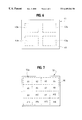
- FIG. 6 is a top view illustrating an image-receiving sheet whose reflection layer is provided with a convexo-concave pattern divided into plural areas.
- FIG. 7 is a top view illustrating an image-receiving sheet whose reflection layer is provided with a convexo-concave pattern divided into areas, wherein the convexo-concave patterns in these areas are composed of plural kinds.
- FIG. 1 is a schematic sectional view illustrating the image-receiving sheet of one embodiment of the present invention.
- an image-receiving sheet 1 comprises a substrate sheet 2 , a reflection layer 3 disposed on one surface side of the substrate sheet 2 , and a receptor layer 5 which covers the reflection layer 3 via a primer layer 4 interposed therebetween, wherein the reflection layer 3 is provided with a convexo-concave pattern 3 a.
- the material for the substrate sheet 2 is not particularly limited, and any material for a conventional image-receiving sheet can be used for the substrate sheet 2 .
- the substrate layer 2 may be transparent or opaque.
- the substrate sheet 2 examples include synthetic papers such as a polyolefin paper and a polystyrene paper; papers such as a fine-quality paper, an art paper, a coated paper, a cast-coated paper, a wall paper, a back-lining paper, a synthetic resin-impregnated paper, an emulsion-impregnated paper, a rubber latex-impregnated paper, a synthetic resin-blended paper and a cardboard; cellulosic papers; plastic films such as a polyolefin film, a polyvinyl chloride film, a polyethylene terephthalate film, a polystyrene film, a polymethacrylate film, and a polycarbonate film; and laminated products of these materials.
- synthetic papers such as a polyolefin paper and a polystyrene paper
- papers such as a fine-quality paper, an art paper, a coated paper, a cast-coated paper, a wall paper, a back
- the substrate sheet 2 include a lightweight coated paper having a basis weight of 60 to 80 g/m 2 , and a biaxially oriented polyethylene terephthalate resin film having a thickness of 50 to 70 ⁇ m. More preferably, the substrate sheet 2 is a film made by a process comprising blending a polyethylene terephthalate resin with white particles such as titanium oxide, barium sulfate, or the like and then biaxially stretching the resulting product.
- a convexo-concave pattern 2 a is disposed on the surface of the substrate 2 where the reflection layer is disposed. Since a reflection layer 3 described later is disposed on the convexo-concave pattern 2 a , the reflection layer 3 is provided with a convexo-concave pattern 3 a .
- the convexo-concave pattern 2 a may be an interference fringe of a hologram or a diffraction grating.
- the hologram may be a plane hologram or a volume hologram.
- a relief hologram is preferred from the standpoint of mass production, durability, and cost.
- a Lippmann hologram is preferred from the standpoint of image reproduction and mass production.
- Other types of hologram include a laser-reproduction hologram such as a Fresnel hologram, a Fraunhofer hologram, a lensless Fourier transform hologram, or an image hologram; and a white light reproduction hologram such as a rainbow hologram.
- holograms utilize the principles of the above-mentioned holograms and there are exemplified as those by a color hologram, a computer hologram, a hologram display, a multiplex hologram, and a holographic stereogram.
- a holographic diffraction grating, a mechanically formed diffraction grating by means of, for example, an electron beam lithography system, or the like can be used as the diffraction grating.
- the convexo-concave pattern 2 a can be formed on the substrate sheet 2 by, for example, a method wherein a press template having a desired convexo-concave pattern formed therein is pressed under heat against the substrate 2 , or a method wherein the surface of the substrate sheet 2 is physically ablated by means of an electron beam lithography system.
- the reflection layer 3 is designed to reflect light in a visual region (having a wavelength in the range of 380 to 700 nm) and is made of a metal having a metallic gloss.
- a metal having a metallic gloss include Zn, Al, In, Ag, Cd, Au, Ge, Sn, Se, Cu, Pb, Bi, Mg, and the like.
- the reflection layer 3 may have a single-layer structure or a multilayer structure.
- the reflection layer 3 can be formed on the substrate 2 by a known method such as vapor deposition, sputtering, plating, or ion plating.
- the thickness of the reflection layer 3 is about 10 to 10000 ⁇ , and preferably about 100 to 5000 ⁇ .
- the reflection layer 3 is provided with the convexo-concave pattern 3 a corresponding to the convexo-concave pattern 2 a.
- the primer layer 4 is designed to increase the adhesion between the reflection layer 3 and the receptor layer 5 .
- the primer layer 4 can be made of a resin such as a polyurethane resin, an acrylic resin, a polyethylene resin, a polypropylene resin, or an epoxy resin, and the thickness of the primer layer 4 is preferably about 0.1 to 25 ⁇ m. It is necessary for the primer layer 4 to have a light transmissivity which allows the reproduction of the hologram. The formation of the primer layer is not necessary in the case where the adhesion between the reflection layer 3 and the receptor layer 5 is good and in the case where the adhesion between the substrate sheets 22 , 32 and the receptor layers 25 and 35 is good.
- the receptor layer 5 is designed to carry a sublimation dye, a heat fusible ink, an ink, or the like in the image formation based on such method as a sublimation type thermal transfer method, a heat fusion type transfer method, or an ink-jet method. It is necessary for the receptor layer 5 to have a light transmissivity allowing the reproduction of the hologram.
- the receptor layer 5 functions as a dye receptor layer which receives the sublimation dye migrating from a thermal transfer sheet and carries the image formed.
- the receptor layer 5 can be made of, for example, a polyolefin resin such as polypropylene; a vinyl resin such as polyvinyl chloride, polyvinylidene chloride, polyvinyl acetate, or polyacrylate; a polyester resin such as polyethylene terephthalate or polybutylene terephthalate; a polystyrene resin; a polyamide resin; a copolymer of an olefin such as ethylene or propylene with other vinyl monomer; an ionomer; a cellulosic resin such as cellulose diacetate; or a polycarbonate resin.
- a polyolefin resin such as polypropylene
- a vinyl resin such as polyvinyl chloride, polyvinylidene chloride, polyvinyl acetate, or polyacrylate
- the receptor layer 5 can be made of a vinyl resin or a polyester resin.
- the receptor layer 5 can be prepared by a process comprising the steps of preparing an ink by dissolving or dispersing the above-mentioned resin and a necessary additive in an appropriate solvent, coating the ink thus prepared on the primer layer 4 by a known means, and then drying the coating.
- the thickness of the receptor layer 5 is preferably about 1 to 20 ⁇ m.
- the receptor layer 5 functions as a layer which receives the heat fusible ink transferred from a thermal transfer sheet and carries the image formed.
- the receptor layer 5 can be made of, for example, a vinyl chloride/vinyl acetate copolymer, an acrylonitrile copolymer, polyester, polyvinyl alcohol, polyurethane, a styrene/butadiene rubber, an acrylic resin, a styrene/acrylic resin, a modified product of a natural resin, or a petroleum resin.
- the thickness of the receptor layer 5 can be, for example, in the range of 1 to 20 ⁇ m.
- the receptor layer 5 suitable for the image formation based on the above-described sublimation type thermal transfer method or heat fusion type transfer method may contain a release agent in an amount within the range of 1 to 30% by weight in order to prevent the sticking between the thermal transfer sheet and the receptor layer 5 or in order to prevent the reduction in the transfer sensitivity.
- the release agent include a silicone oil, a surfactant based on a phosphoric ester, and a surfactant based on a fluorine-containing compound.
- a silicone oil is preferable as the release agent.
- the silicone oil is preferably a modified silicone oil such as an epoxy-modified silicone oil, a vinyl-modified silicone oil, an alkyl-modified silicone oil, an amino-modified silicone oil, a carboxyl-modified silicone oil, an alcohol-modified silicone oil, a fluorine-modified silicone oil, an alkylaralkylpolyether-modified silicone oil, an epoxy/polyether-modified silicone oil, or a polyether-modified silicone oil.
- a modified silicone oil such as an epoxy-modified silicone oil, a vinyl-modified silicone oil, an alkyl-modified silicone oil, an amino-modified silicone oil, a carboxyl-modified silicone oil, an alcohol-modified silicone oil, a fluorine-modified silicone oil, an alkylaralkylpolyether-modified silicone oil, an epoxy/polyether-modified silicone oil, or a polyether-modified silicone oil.
- the receptor layer 5 functions as a layer which absorbs the water component of the adherent ink so as to solidify the ink by drying and carries the image formed.
- the receptor layer 5 can be a receptor layer hitherto known for use in an ink jet method.
- the receptor layer 5 may be a layer comprising a water-soluble polymer and a filler incorporated therein which absorbs the water component of the ink so that the drying of the ink is facilitated.
- water-soluble polymer examples include vinyl polymers and derivatives thereof such as polyvinyl alcohol, polyvinyl pyrrolidone, a polyvinylpyridinium halide, and a cation-modified polyvinyl alcohol; acrylic group-containing polymers such as polyacrylamide, polydimethylacrylamide, polydimethyl aminoacrylate, sodium polyacrylate, and an acrylic acid/vinyl alcohol copolymer; naturally occurring polymers or derivatives thereof such as starch, oxidized starch, carboxylated starch, starchdialdehyde, cationized starch, dextrin, sodium alginate, gum arabic, casein, methyl cellulose, ethyl cellulose, carboxymethyl cellulose, hydroxyethyl cellulose, and hydroxybutyl cellulose; and synthetic polymers such as polyethylene glycol, polypropylene glycol, polyvinyl ether, a maleic acid/alkyl vinyl ether copolymer, a maleic acid/N-
- the receptor layer 5 may contain an anti-static agent.
- anti-static agent examples include known ones exemplified by cationic anti-static agents such as a quaternary ammonium salt and a polyamine derivative; anionic anti-static agents such as alkyl phosphates; and nonionic anti-static agents such as fatty acid esters.
- FIG. 2 is a schematic sectional view illustrating the image-receiving sheet of another embodiment of the present invention.
- an image-receiving sheet 1 ′ comprises a substrate sheet 2 , a reflection layer 3 , a primer layer 4 , a receptor layer 5 , an adhesive layer 8 , and a release sheet 9 .
- a reflection layer 3 , a primer layer 4 , and a receptor layer 5 are disposed in this order on one surface side of the substrate sheet 2 .
- an adhesive layer 8 and a release sheet 9 are disposed in this order on the other surface side of the substrate sheet 2 .
- the substrate sheet 2 , the reflection layer 3 , the primer layer 4 , and the receptor layer 5 are the same as those in the aforedescribed image-receiving sheet 1 , the explanation about them is omitted.
- the adhesive layer 8 for the image-receiving sheet 1 ′ may be made of a synthetic resin, a natural resin, a rubber, a wax, or the like. Specific examples of these materials include cellulosic derivatives such as ethyl cellulose and cellulose acetate propionate; styrenic resins such as polystyrene and poly ⁇ -methylstyrene; acrylic resins such as polymethyl methacrylate and polyethyl acrylate; vinyl resins such as polyvinyl chloride, polyvinyl acetate, a vinyl chloride/vinyl acetate copolymer, polyvinyl butyral, and polyvinyl acetal; another synthetic resins such as polyester resins, polyamide resins, epoxy resins, polyurethane resins, an ionomer, an ethylene/acrylic acid copolymer and an ethylene/acrylate copolymer; tackifiers such as rosin and a rosin-modified maleic
- the adhesive layer 8 may comprise a composition composed of one or two, or more, of these materials. Although the thickness of the adhesive layer 8 may be selected by taking into account the required adhesive capacity and ease in handling, the thickness is preferably about 5 to 30 ⁇ m in a normal case.
- the release sheet 9 for the image-receiving sheet 1 ′ is obtained by treating the surface of a traditionally known plastic film or synthetic paper with a traditionally known release agent such as a silicone for the purpose of improving releasability of the surface.
- the plastic films may be those previously enumerated for the substrate sheet 2 .
- these plastic films particularly preferred is a polyolefin resin film whose surface is not treated.
- Examples of the synthetic paper include a film obtained by extruding and stretching a blend of a polyolefin resin with a filler, and a film obtained by coating a resin film, such as a polyolefin film, a polystyrene film, or a polyester film, with a blend comprising a filler and a binder.
- the thickness of the release sheet 9 may be set to an appropriate value within the range of 20 to 100 ⁇ m.
- the peel strength between the adhesive layer 8 and the release sheet 9 as measured according to JIS P8139 may be set to an appropriate value within the range of 40 to 900 g, and preferably within the range of 100 to 700
- FIG. 3 is a schematic sectional view illustrating the image-receiving sheet of another embodiment of the present invention.
- an image-receiving sheet 11 comprises a substrate sheet 12 as well as a hologram layer 16 , a reflection layer 13 , a primer layer 14 and a receptor layer 15 disposed in this order on one surface side of the substrate sheet 12 .
- the image-receiving sheet 11 differs from the aforedescribed image-receiving sheet 1 in that the image-receiving sheet 11 comprises the hologram layer 16 interposed between the substrate sheet 12 and the reflection layer 13 and in that the substrate sheet 12 is not provided with a convexo-concave pattern.
- each constituting the image-receiving sheet 11 can be the same as the substrate sheet 2 , the primer layer 4 , and the receptor layer 5 , each constituting the aforedescribed image-receiving sheet 1 , the explanation about them is omitted.
- the hologram layer 16 is provided with a convexo-concave pattern 16 a (interference fringe) and may be a plane hologram or a volume hologram.
- a convexo-concave pattern 16 a interference fringe
- a plane hologram a relief hologram is preferable from the standpoint of mass production, durability and cost.
- a volume hologram a Lippmann hologram is preferable from the standpoint of image reproduction and mass production.
- a laser-reproduction hologram such as a Fresnel hologram, a Fraunhofer hologram, a lensless Fourier transform hologram, or an image hologram as well as a white light reproduction hologram such as a rainbow hologram, can also be used.
- a color hologram, a computer hologram, a hologram display, a multiplex hologram, a holographic stereogram, a holographic diffraction grating, and the like can also be used.
- thermoplastic resins such as polyvinyl chloride, an acrylic resin, e.g., polymethyl methacrylate, polystyrene, and polycarbonate
- thermosetting resins such as unsaturated polyester, melamine, epoxy, polyester(meth)acrylate, urethane(meth)acrylate, epoxy(meth)acrylate, polyether(meth)acrylate, polyol(meth)acrylate, melamine(meth)acrylate, and triazine-based acrylate
- the hologram layer 16 can be formed by a conventionally known method.
- a hologram original plate which has an interference fringe recorded as a convexo-concave pattern
- the process comprises the steps of superposing a hologram-forming resin sheet composed of the aforedescribed material on the hologram original plate, pressing the sheet against the original plate under heat by means of, for example, heating rolls so that a convexo-concave pattern of the hologram original plate is duplicated on the surface of the hologram-forming resin sheet to thereby prepare a resin sheet having a surface relieved with a pattern.
- the hologram layer 16 can be obtained by laminating the resin sheet thus prepared onto the substrate sheet 12 .
- the hologram layer 16 can be duplicated by a process comprises the steps of coating a photosensitive polymer on the substrate sheet 12 , stacking face to face the coated substrate sheet 12 and a hologram original plate prepared in advance, and irradiating the stack with laser light in the shape of a slit. A developing treatment or the like may be further performed.
- a layer provided with, for example, an interference fringe of diffraction grating as a convexo-concave pattern may be disposed in place of the hologram layer 16 .
- the reflection layer 13 is designed to reflect the light in a visual region (having a wavelength in the range of 380 to 700 nm) and is made of a metal having a metallic gloss as in the case of the reflection layer 3 constituting the aforedescribed image-receiving sheet 1 . Further, the reflection layer 13 may be a transparent thin film having an index of refraction different from that of the hologram 16 or may be a reflective thin film of a metal having a thickness of 200 ⁇ or less.
- the index of refraction may be greater or smaller than that of the hologram 16 .
- the difference in the index of refraction be 0.1 or more, and preferably 0.5 or more, and the value of the index of refraction be 1.0 or more.
- the following compounds can be used.
- TiO 2 (having an index of refraction of 2.3)
- LiF (having an index of refraction of 1.4)
- Polytetrafluoroethylene (having an index of refraction of 1.35)
- Polypropylene (having an index of refraction of 1.49)
- Polyvinylidene chloride (having an index of refraction of 1.60 to 1.63)
- the thickness of the transparent thin film is not particularly limited in so far as the thickness is within a range securing the transparency. Although a thickness can be appropriately selected depending on the material to be used, the thickness is usually about 10 to 10000 ⁇ , and preferably about 100 to 5000 ⁇ .
- the film as thin as 200 ⁇ or less has a high transmissivity to light waves so that the film exhibits a diffraction or hologram effect but does not hide the display portion. That is, when light waves pass through the thin film of a reflective metal, since the amplitude abruptly decreases according to exp( ⁇ 2 ⁇ K) per wavelength, the transmissivity considerably decreases if the thickness exceeds 200 ⁇ . Accordingly, a film thickness of 200 ⁇ or less secures a sufficient transmissivity of the film, while the film exhibits a diffraction or hologram effect.
- a problem associated with a conventional technology i.e., disagreeable silver gray appearance having a high brightness, can be eliminated by use of the film having a thickness of 200 ⁇ or less.
- Such a thin film of a reflective metal has a complex index of refraction, and the complex index of refraction n
- n* n ⁇ iK
- K denotes a coefficient of absorption
- metals such as Sn, In, Te, Ti, Fe, Co, Zn, Ge, Pb, Cd, Bi, Se, Ga, Rb, and the like.
- oxides, nitrides, and the like of these metals are also usable.
- the metals, oxides of the metals, and nitrides of the metals may be used singly or in a combination of two or more of them.
- the adhesive layer and the release sheet may be disposed face to face on the substrate sheet 12 on the surface side thereof opposite to the surface side where the receptor layer 15 is disposed, as in the case of the aforedescribed image-receiving sheet 1 ′.
- FIG. 4 is a schematic sectional view illustrating the image-receiving sheet of another embodiment of the present invention.
- an image-receiving sheet 21 comprises a substrate sheet 22 as well as a reflection layer 23 , a primer layer 24 and a receptor layer 25 .
- the primer layer 24 and the receptor layer 25 are disposed in this order on one surface side of the substrate sheet 22 , while the reflection layer 23 is disposed on the other surface side of the substrate sheet 22 .
- the image-receiving sheet 21 differs from the aforedescribed image-receiving sheet 1 in that the image-receiving sheet 21 comprises the reflection layer 23 on the substrate sheet 22 on the surface side thereof opposite to the surface side where the receptor layer 25 is disposed.
- the reflection layer 23 and the receptor layer 25 are disposed on opposite surface sides of the substrate sheet 22 respectively in the image-receiving sheet 21 . Because of this, in order that the optical information formed by the reflection layer 23 can be recognized from the side of the receptor layer 25 , the substrate sheet 22 needs to be made of a transparent material.
- the material for the substrate sheet 22 can be selected from the transparent materials exemplified as the materials for the substrate sheet 2 of the image-receiving sheet 1 .
- a convexo-concave pattern 22 a is formed in advance on the substrate sheet 22 on the surface side thereof where a reflection layer will be formed. Then, a reflection layer 23 is formed on the convexo-concave pattern 22 a . In this way, a convexo-concave pattern 23 a is formed on the reflection layer 23 . Since the formation of the convexo-concave pattern 22 a on the substrate sheet 22 can be carried out by the same process as in the formation of the convexo-concave pattern 2 a on the substrate sheet 2 , the explanation of the process is omitted.
- a foamed resin film may be interposed between the substrate sheet 22 and the primer layer 24 .
- a conventionally known foamed resin film such as a foamed polypropylene film or a foamed polyethylene terephthalate film, can be used as the foamed resin film.
- the thickness of the foamed resin film is preferably about 30 to 60 ⁇ m. The use of such a foamed resin film makes it possible to increase the color forming density, and particularly the density of the high-density portion, of the image to be formed in the receptor layer 25 and, as a result, enhances the image quality.
- each constituting the image-receiving sheet 21 can be the same as the reflection layer 3 , the primer layer 4 , and the receptor layer 5 , each constituting the aforedescribed image-receiving sheet 1 , the explanation about them is omitted.
- the adhesive layer and the release sheet may be disposed face to face on the reflection layer 23 , as in the case of the aforedescribed image-receiving sheet
- FIG. 5 is a schematic sectional view illustrating the image-receiving sheet of yet another embodiment of the present invention.
- an image-receiving sheet 31 comprises a substrate sheet 32 as well as a reflection layer 33 , a primer layer 34 , a receptor layer 35 , and a hologram layer 36 .
- the primer layer 34 and the receptor layer 35 are disposed in this order on one surface side of the substrate sheet 32
- the hologram layer 36 and the reflection layer 33 are disposed in this order on the other surface side of the substrate sheet 32 .
- the image-receiving sheet 31 differs from the aforedescribed image-receiving sheet 11 in that the image-receiving sheet 31 comprises the reflection layer 33 and the hologram layer 36 on the substrate sheet 32 on the surface side thereof opposite to the surface side where the receptor layer 35 is disposed.
- the reflection layer 33 and the receptor layer 35 are disposed on opposite surface sides of the substrate sheet 32 respectively in the image-receiving sheet 31 . Because of this, in order that the optical information formed by the reflection layer 33 can be recognized from the side of the receptor layer 35 , the substrate sheet 32 needs to be made of a transparent material.
- the material for the substrate sheet 32 can be selected from the transparent materials exemplified as the materials for the substrate sheet 2 of the image-receiving sheet 1 .
- a foamed resin film may be interposed between the substrate sheet 32 and the primer layer 34 .
- a conventionally known foamed resin film such as a foamed polypropylene film or a foamed polyethylene terephthalate film, can be used as the foamed resin film.
- the thickness of the foamed resin film is preferably about 30 to 60 ⁇ m.
- the hologram layer 36 which constitutes the image-receiving sheet 31 , is provided with a convexo-concave pattern 36 a . Since the formation of the hologram layer 26 can be carried out by the same process as in the formation of the hologram layer 16 constituting the image-receiving sheet 11 , the explanation of the process is omitted.
- the reflection layer 33 disposed on the hologram layer 36 is provided with a convexo-concave pattern 33 a corresponding to the convexo-concave pattern 36 a of the hologram layer 36 .
- the reflection layer 33 having this structure can be formed in the same way as in the formation of the reflection layer 6 constituting the image-receiving sheet 1 .
- primer layer 34 and the receptor layer 35 can be formed in the same way as in the formation of the primer layer 4 and the receptor layer 5 which constitute the aforedescribed image-receiving sheet 1 .
- the adhesive layer and the release sheet may be disposed face to face on the reflection layer 33 , as in the case of the aforedescribed image-receiving sheet 1 .
- the areas having convexo-concave patterns 3 a , 13 a , 23 a , and 33 a of the respective reflection layers 3 , 13 , 23 , and 33 coincide, respectively, with the areas where the receptor layers 5 , 15 , 25 , and 35 are formed.
- the reflection layer may be formed partly on the substrate sheet, or alternatively the convexo-concave pattern may be formed partly on the reflection layer.
- the area provided with the convexo-concave pattern of the reflection layer extends within the area provided with the receptor layer. Further, according to the present invention, if the reflection layer and the receptor layer are disposed on the same surface side of the substrate, the reflection layer is interposed between the substrate sheet and the receptor layer.
- FIG. 6 is a top view which is seen from the receptor layer side and illustrates an image-receiving sheet of the present invention whose reflection layer is provided with a convexo-concave pattern divided into plural areas.
- an image-receiving sheet 41 is provided with a receptor layer 45 in the entire area of the substrate sheet.
- the reflection layer formed either between the receptor layer 45 and the substrate sheet or on the other surface side of the substrate sheet, is provided with a convexo-concave pattern 43 a divided into four areas (shown by broken lines).
- the convexo-concave pattern 43 a of the reflection layer can be recognized through the receptor layer 45 and a special image effect can be imparted to the image formed in the receptor layer 45 .
- the convexo-concave pattern comprises an interference fringe of a hologram, the optical information by reflected light can be superposed on the image information of the receptor layer 45 , and thus a visual effect, a counterfeit preventing effect, and an alteration preventing effect can be obtained.
- the reflection layer may be provided with a convexo-concave pattern divided into plural areas, and the convexo-concave patterns in these areas may be composed of plural kinds.
- FIG. 7 is a top view which is seen from the receptor layer side of an image-receiving sheet of the present invention whose reflection layer is provided with a convexo-concave pattern divided into plural areas.
- an image-receiving sheet 51 is provided with a receptor layer 55 in the entire area of the substrate sheet.
- the reflection layer which is formed either between the receptor layer 55 and the substrate sheet or on the other surface side of the substrate sheet, is provided with a convexo-concave pattern 53 a divided into 16 areas (shown by broken lines), wherein the convexo-concave patterns in these areas are composed of 16 kinds (A 1 ⁇ A 16 ). Since the area of he convexo-concave pattern 53 a also extends within the area of the receptor layer 55 , the convexo-concave pattern 53 a of the reflection layer can be recognized through the receptor layer 55 .
- an image-receiving sheet comprises the adhesive layer 8 and the release sheet 9 as in the aforedescribed image-receiving sheet 1 ′
- a slit half cut in any shape may be formed in the multilayered structure of the image-receiving sheet excluding the release sheet 9 .
- This slit which is discontinuous in particular, prevents the area enclosed by the slit from being peeled off when, for example, an image is formed in the receptor layer.
- the area where the image is formed can be peeled off and is then affixed to other article.
- the reflection layer may be formed on both surface sides of the substrate sheet. However, if the reflection layer is formed on both surface sides of the substrate sheet, it is desirable that the areas where the reflection layer is formed do not overlap with each other.
- a 50 ⁇ m thick polyethylene terephthalate sheet (“Lumirror T-60” manufactured by Toray Industries, Inc. Co., Ltd.) was used as a substrate sheet.
- a coating liquid having the following composition was applied to one surface side of the substrate sheet and thus a resin layer (having a thickness of 3 ⁇ m) for the formation of a hologram layer was produced.
- Acrylic resin 40 parts by weight
- Melamine resin 10 parts by weight
- Cyclohexanone 50 parts by weight
- Methyl ethyl ketone 50 parts by weight
- a hologram original plate of a rainbow hologram was superposed on the resin layer, and the original plate was pressed under heat against the resin layer (150° C., 50 kg/cm 2 , 1 minute). After that, the hologram original plate was peeled from the resin layer. In this way, a hologram relief was formed on the resin layer, and this layer was used as a hologram layer.
- a coating liquid for primer layer having the following composition was applied (at a coating weight based on solids of 0.6 g/m 2 ) to the reflection layer. The coating was dried, and thus a primer layer was formed. Further, a coating liquid for a receptor layer (dye receptor layer) having the following composition was applied (at a coating weight based on solids of 4 g/m 2 ) to the primer layer. The coating was dried, and thus a receptor layer was formed. In this way, an image-receiving sheet of the present invention having a structure as shown in FIG. 3 was prepared.
- THF Primer (manufactured by 100 parts by weight The Inktech Co., Ltd.): XEL Hardener (D) (manufactured by 5 parts by weight The Inktech Co., Ltd.): Toluene: 100 parts by weight Methyl ethyl ketone: 100 parts by weight
- Vinyl chloride/vinyl acetate copolymer 40 parts by weight (Denkalac #1000A manufactured by Denki Kagaku Kogyo Co., Ltd.): Polyester resin (Vylon 600 manufactured 40 parts by weight by Toyobo Co., Ltd.): Vinyl chloride/styrene/acrylic copolymer 20 parts by weight (Denkalac #400A manufactured by Denki Kagaku Kogyo Co., Ltd.): Vinyl-modified silicone (X-62-1212 10 parts by weight manufactured by Shin-Etsu Chemical Co., Ltd.): Catalyst (CAT-PLR-5 manufactured 5 parts by weight by Shin-Etsu Chemical Co., Ltd.): Catalyst (CAT-PL-50T manufactured 6 parts by weight by Shin-Etsu Chemical Co., Ltd.):
- an adhesive agent having the following composition (at a coating weight based on solids of 15 g/m 2 ) and the coating was dried (70° C. for 1 minute) to thereby prepare an adhesive layer.
- a biaxially oriented polypropylene film (Pylen P2156 having a thickness of 50 ⁇ m manufactured by Toyobo Co., Ltd.) whose surface was not treated was laminated face to face to the adhesive layer. In this way, an image-receiving sheet of the present invention was prepared.
- the image-receiving sheet thus obtained was put together with a sublimation type thermal transfer sheet (manufactured by Dai Nippon Printing Co., Ltd.) having 3 dye layers, i.e., a yellow dye layer, a cyan dye layer, and a magenta dye layer, disposed side by side on the surface thereof, so that the receptor layer faced the dye layers.
- the image formation was performed by using a thermal head applied to the backside of the sublimation type thermal transfer sheet. The condition was as follows: applied voltage to the head: 12 V; pulse width: 16 m.second; printing cycle: 33.3 m.second; dot density: 6 dots/line. In this way, a full-color photograph of a person's face was formed in the receptor layer of the image-receiving sheet.
Landscapes
- Physics & Mathematics (AREA)
- General Physics & Mathematics (AREA)
- Holo Graphy (AREA)
- Credit Cards Or The Like (AREA)
- Thermal Transfer Or Thermal Recording In General (AREA)
- Ink Jet Recording Methods And Recording Media Thereof (AREA)
- Laminated Bodies (AREA)
Abstract
There is provided an image receiving sheet which comprises: a substrate sheet, a reflection layer disposed on at least one surface side of the substrate sheet so as to be laid on at least one area thereof, and a receptor layer disposed on at least one surface side of the substrate sheet, wherein the reflection layer has at least one area provided with a convexo-concave pattern, the area provided with the convexo-concave pattern of the reflection layer being extended within an area provided with the receptor layer. The reflection layer is disposed, as required, either on the same surface side of the substrate sheet as the receptor layer is disposed so as to be interposed between the substrate sheet and the receptor layer or on the opposite side of a transparent substrate sheet to the surface provided with the receptor layer. The convexo-concave pattern may comprise an interference fringe, and may be divided into plural areas. The divided convexo-concave pattern may be composed of a single or plural kinds of pattern. The receptor layer is disposed on only one surface side of the substrate sheet, and the adhesive layer and the release sheet are disposed in this order on the other surface side, as required.
Description
The present invention relates to an image-receiving sheet. More specifically, the present invention relates to an image-receiving sheet which can form a high-quality image and which provides optical information by reflected light.
Heretofore, a printer based on such method as a sublimation type thermal transfer method, a heat fusion type transfer method, or an ink-jet method is used for the output print of a computer or a word processor. In addition, because of the recent progress of an image forming system represented by photographic technology and computer graphics, there has been a growing demand for hard copies of color images.
The image formation according to the above-mentioned methods is performed by using a sheet provided with a receptor layer designed to carry a sublimation dye, a heat fusible ink, an ink, or the like. Usually, this image-receiving sheet is a white sheet or a transparent sheet. On some occasions, after image formation, the image-receiving sheet is provided with a hologram by transfer, lamination or the like for such purpose as prevention of counterfeiting, prevention of alteration, or for addition of a special effect to the image.
However, the formation of the hologram on the receptor layer after image formation thereon has been associated with the following problems. That is, it is necessary to use a special printer which is provided with both an image forming step and a hologram forming step. Alternatively, it is necessary to use a special device for the hologram formation separately from a printer for the image formation. Because of this, the image formation becomes less easy and an increase in cost is unavoidable. Further, the hologram formation by, for example, use of a thin film of metallic vapor deposition must be avoided because the film hides the image already formed in the receptor layer, and therefore a significant restriction has been imposed on the hologram formation.
Meanwhile, the use of an ordinary printing method makes it possible to print an image on a sheet on which a hologram or a thin film of metallic vapor deposition is provided in advance. This case, however, presents a problem that it is difficult to individually deal with private or specific information unlike the case of the aforementioned thermal transfer method or inkjet method.
The object of the present invention is to provide an image-receiving sheet which can produce a high-quality image based on private or specific information and which provides optical information by reflected light.
The image-receiving sheet of the present invention comprises a substrate sheet, a reflection layer disposed on at least one surface side of the substrate sheet so as to be laid on at least one area thereof, and a receptor layer disposed on at least one surface side of the substrate, wherein said reflection layer has at least one area provided with a convexo-concave pattern, the area provided with the convexo-concave pattern of the reflection layer being extended within an area provided with the receptor layer.
Since the image-receiving sheet of the present invention makes it possible to form an image in the receptor layer by a thermal transfer method, an ink-jet method, or the like, it is possible to form a high-quality image based on private information. According to the image-receiving sheet of the present invention, the light reflected by the convexo-concave pattern of the reflection layer can be recognized through the receptor layer. Because of this, a special effect can be imparted to the image formed in the receptor layer. Since these effects can be obtained by use of an image forming printer which is based on a thermal transfer method, an ink-jet method, or the like and which is not provided with the hologram forming step, the image formation is easy and cost does not increase. Further, the image is not hidden even if a light-screening film, such as a thin film of metallic vapor deposition, is used in the refection layer, and therefore no restriction is imposed on the hologram.
According to an embodiment of the present invention, the reflection layer and the receptor layer are disposed on the same surface side of the substrate sheet, and the reflection layer is interposed between the substrate sheet and the receptor layer.
According to this embodiment, since the substrate sheet is not interposed between receptor layer and the reflection layer, a material which is not transparent can be used as the substrate sheet, and therefore the latitude for selection of the substrate sheet can be widened.
Alternatively, the reflection layer and the receptor layer may be disposed on opposite surface sides of the substrate sheet respectively, provided, however, that the substrate sheet is composed of a transparent material.
According to an embodiment of the present invention, the convexo-concave pattern comprises an interference fringe of a hologram.
According to this embodiment, since the convexo-concave pattern comprises an interference fringe of a hologram and therefore the optical information by reflected light can be superposed on the image information of the receptor layer, a visual effect, a counterfeit preventing effect, and an alteration preventing effect can be obtained.
The convexo-concave pattern may be divided into plural areas. In this case, the convexo-concave patterns in plural areas may be composed of a single kind, or they may be composed of plural kinds.
According to an embodiment of the image-receiving sheet of the present invention, the receptor layer is disposed on only one surface side of the substrate sheet, and an adhesive layer and a release sheet are disposed in this order on the other surface side of the substrate sheet.
According to this embodiment, since the adhesive layer and a release sheet are disposed on one surface side of the substrate sheet to thereby produce a labeling form, private information provided with a special image effect can be easily affixed to various members.
FIG. 1 is a sectional view illustrating a first embodiment of the image-receiving sheet of the present invention.
FIG. 2 is a sectional view illustrating a second embodiment of the image-receiving sheet of the present invention.
FIG. 3 is a sectional view illustrating a third embodiment of the image-receiving sheet of the present invention.
FIG. 4 is a sectional view illustrating a fourth embodiment of the image-receiving sheet of the present invention.
FIG. 5 is a sectional view illustrating a fifth embodiment of the image-receiving sheet of the present invention.
FIG. 6 is a top view illustrating an image-receiving sheet whose reflection layer is provided with a convexo-concave pattern divided into plural areas.
FIG. 7 is a top view illustrating an image-receiving sheet whose reflection layer is provided with a convexo-concave pattern divided into areas, wherein the convexo-concave patterns in these areas are composed of plural kinds.
The embodiments of the present invention will be explained below by referring to the drawings.
FIG. 1 is a schematic sectional view illustrating the image-receiving sheet of one embodiment of the present invention. As shown in FIG. 1, an image-receiving sheet 1 comprises a substrate sheet 2, a reflection layer 3 disposed on one surface side of the substrate sheet 2, and a receptor layer 5 which covers the reflection layer 3 via a primer layer 4 interposed therebetween, wherein the reflection layer 3 is provided with a convexo-concave pattern 3 a.
The material for the substrate sheet 2 is not particularly limited, and any material for a conventional image-receiving sheet can be used for the substrate sheet 2. In addition, since the reflection layer 3 and the receptor layer 5 are disposed only on the same surface side of the substrate 2, the substrate layer 2 may be transparent or opaque. Examples of the substrate sheet 2 include synthetic papers such as a polyolefin paper and a polystyrene paper; papers such as a fine-quality paper, an art paper, a coated paper, a cast-coated paper, a wall paper, a back-lining paper, a synthetic resin-impregnated paper, an emulsion-impregnated paper, a rubber latex-impregnated paper, a synthetic resin-blended paper and a cardboard; cellulosic papers; plastic films such as a polyolefin film, a polyvinyl chloride film, a polyethylene terephthalate film, a polystyrene film, a polymethacrylate film, and a polycarbonate film; and laminated products of these materials. Preferred examples of the substrate sheet 2 include a lightweight coated paper having a basis weight of 60 to 80 g/m2, and a biaxially oriented polyethylene terephthalate resin film having a thickness of 50 to 70 μm. More preferably, the substrate sheet 2 is a film made by a process comprising blending a polyethylene terephthalate resin with white particles such as titanium oxide, barium sulfate, or the like and then biaxially stretching the resulting product.
According to this embodiment, a convexo-concave pattern 2 a is disposed on the surface of the substrate 2 where the reflection layer is disposed. Since a reflection layer 3 described later is disposed on the convexo-concave pattern 2 a, the reflection layer 3 is provided with a convexo-concave pattern 3 a. The convexo-concave pattern 2 a may be an interference fringe of a hologram or a diffraction grating.
The hologram may be a plane hologram or a volume hologram. In the case of a plane hologram, a relief hologram is preferred from the standpoint of mass production, durability, and cost. In the case of a volume hologram, a Lippmann hologram is preferred from the standpoint of image reproduction and mass production. Other types of hologram include a laser-reproduction hologram such as a Fresnel hologram, a Fraunhofer hologram, a lensless Fourier transform hologram, or an image hologram; and a white light reproduction hologram such as a rainbow hologram. Also usable are the holograms utilize the principles of the above-mentioned holograms and there are exemplified as those by a color hologram, a computer hologram, a hologram display, a multiplex hologram, and a holographic stereogram.
A holographic diffraction grating, a mechanically formed diffraction grating by means of, for example, an electron beam lithography system, or the like can be used as the diffraction grating.
The convexo-concave pattern 2 a can be formed on the substrate sheet 2 by, for example, a method wherein a press template having a desired convexo-concave pattern formed therein is pressed under heat against the substrate 2, or a method wherein the surface of the substrate sheet 2 is physically ablated by means of an electron beam lithography system.
The reflection layer 3 is designed to reflect light in a visual region (having a wavelength in the range of 380 to 700 nm) and is made of a metal having a metallic gloss. Specific examples of the metal include Zn, Al, In, Ag, Cd, Au, Ge, Sn, Se, Cu, Pb, Bi, Mg, and the like.
The reflection layer 3 may have a single-layer structure or a multilayer structure. The reflection layer 3 can be formed on the substrate 2 by a known method such as vapor deposition, sputtering, plating, or ion plating. The thickness of the reflection layer 3 is about 10 to 10000 Å, and preferably about 100 to 5000 Å. As described previously, since the reflection layer 3 is formed on the convexo-concave pattern 2 a which is formed on the substrate sheet 2 in advance, the reflection layer 3 is provided with the convexo-concave pattern 3 a corresponding to the convexo-concave pattern 2 a.
The primer layer 4 is designed to increase the adhesion between the reflection layer 3 and the receptor layer 5. The primer layer 4 can be made of a resin such as a polyurethane resin, an acrylic resin, a polyethylene resin, a polypropylene resin, or an epoxy resin, and the thickness of the primer layer 4 is preferably about 0.1 to 25 μm. It is necessary for the primer layer 4 to have a light transmissivity which allows the reproduction of the hologram. The formation of the primer layer is not necessary in the case where the adhesion between the reflection layer 3 and the receptor layer 5 is good and in the case where the adhesion between the substrate sheets 22, 32 and the receptor layers 25 and 35 is good.
The receptor layer 5 is designed to carry a sublimation dye, a heat fusible ink, an ink, or the like in the image formation based on such method as a sublimation type thermal transfer method, a heat fusion type transfer method, or an ink-jet method. It is necessary for the receptor layer 5 to have a light transmissivity allowing the reproduction of the hologram.
In the case of the image formation according to a sublimation type thermal transfer method, the receptor layer 5 functions as a dye receptor layer which receives the sublimation dye migrating from a thermal transfer sheet and carries the image formed. The receptor layer 5 can be made of, for example, a polyolefin resin such as polypropylene; a vinyl resin such as polyvinyl chloride, polyvinylidene chloride, polyvinyl acetate, or polyacrylate; a polyester resin such as polyethylene terephthalate or polybutylene terephthalate; a polystyrene resin; a polyamide resin; a copolymer of an olefin such as ethylene or propylene with other vinyl monomer; an ionomer; a cellulosic resin such as cellulose diacetate; or a polycarbonate resin. Most preferably, the receptor layer 5 can be made of a vinyl resin or a polyester resin. The receptor layer 5 can be prepared by a process comprising the steps of preparing an ink by dissolving or dispersing the above-mentioned resin and a necessary additive in an appropriate solvent, coating the ink thus prepared on the primer layer 4 by a known means, and then drying the coating. The thickness of the receptor layer 5 is preferably about 1 to 20 μm.
In the case of the image formation according to a heat fusion type transfer method, the receptor layer 5 functions as a layer which receives the heat fusible ink transferred from a thermal transfer sheet and carries the image formed. The receptor layer 5 can be made of, for example, a vinyl chloride/vinyl acetate copolymer, an acrylonitrile copolymer, polyester, polyvinyl alcohol, polyurethane, a styrene/butadiene rubber, an acrylic resin, a styrene/acrylic resin, a modified product of a natural resin, or a petroleum resin. The thickness of the receptor layer 5 can be, for example, in the range of 1 to 20 μm.
The receptor layer 5 suitable for the image formation based on the above-described sublimation type thermal transfer method or heat fusion type transfer method, may contain a release agent in an amount within the range of 1 to 30% by weight in order to prevent the sticking between the thermal transfer sheet and the receptor layer 5 or in order to prevent the reduction in the transfer sensitivity. Examples of the release agent include a silicone oil, a surfactant based on a phosphoric ester, and a surfactant based on a fluorine-containing compound. A silicone oil is preferable as the release agent. The silicone oil is preferably a modified silicone oil such as an epoxy-modified silicone oil, a vinyl-modified silicone oil, an alkyl-modified silicone oil, an amino-modified silicone oil, a carboxyl-modified silicone oil, an alcohol-modified silicone oil, a fluorine-modified silicone oil, an alkylaralkylpolyether-modified silicone oil, an epoxy/polyether-modified silicone oil, or a polyether-modified silicone oil. Alternatively, it is also possible to dispose a layer comprising the above-mentioned release agent on the receptor layer 5.
In the case of the image formation according to an ink jet method, the receptor layer 5 functions as a layer which absorbs the water component of the adherent ink so as to solidify the ink by drying and carries the image formed. The receptor layer 5 can be a receptor layer hitherto known for use in an ink jet method. For example, the receptor layer 5 may be a layer comprising a water-soluble polymer and a filler incorporated therein which absorbs the water component of the ink so that the drying of the ink is facilitated. Examples of the water-soluble polymer include vinyl polymers and derivatives thereof such as polyvinyl alcohol, polyvinyl pyrrolidone, a polyvinylpyridinium halide, and a cation-modified polyvinyl alcohol; acrylic group-containing polymers such as polyacrylamide, polydimethylacrylamide, polydimethyl aminoacrylate, sodium polyacrylate, and an acrylic acid/vinyl alcohol copolymer; naturally occurring polymers or derivatives thereof such as starch, oxidized starch, carboxylated starch, starchdialdehyde, cationized starch, dextrin, sodium alginate, gum arabic, casein, methyl cellulose, ethyl cellulose, carboxymethyl cellulose, hydroxyethyl cellulose, and hydroxybutyl cellulose; and synthetic polymers such as polyethylene glycol, polypropylene glycol, polyvinyl ether, a maleic acid/alkyl vinyl ether copolymer, a maleic acid/N-vinylpyrrole copolymer, and polyethyleneimine. Examples of the filler include silica and porous beads. The thickness of the receptor layer 5 is preferably about 3 to 50 μm.
The receptor layer 5 may contain an anti-static agent. Examples of the anti-static agent are known ones exemplified by cationic anti-static agents such as a quaternary ammonium salt and a polyamine derivative; anionic anti-static agents such as alkyl phosphates; and nonionic anti-static agents such as fatty acid esters.
FIG. 2 is a schematic sectional view illustrating the image-receiving sheet of another embodiment of the present invention. As shown in FIG. 2, an image-receiving sheet 1′ comprises a substrate sheet 2, a reflection layer 3, a primer layer 4, a receptor layer 5, an adhesive layer 8, and a release sheet 9. A reflection layer 3, a primer layer 4, and a receptor layer 5 are disposed in this order on one surface side of the substrate sheet 2. Meanwhile, an adhesive layer 8 and a release sheet 9 are disposed in this order on the other surface side of the substrate sheet 2.
Since the substrate sheet 2, the reflection layer 3, the primer layer 4, and the receptor layer 5, each constituting the image-receiving sheet 1′, are the same as those in the aforedescribed image-receiving sheet 1, the explanation about them is omitted.
The adhesive layer 8 for the image-receiving sheet 1′ may be made of a synthetic resin, a natural resin, a rubber, a wax, or the like. Specific examples of these materials include cellulosic derivatives such as ethyl cellulose and cellulose acetate propionate; styrenic resins such as polystyrene and poly α-methylstyrene; acrylic resins such as polymethyl methacrylate and polyethyl acrylate; vinyl resins such as polyvinyl chloride, polyvinyl acetate, a vinyl chloride/vinyl acetate copolymer, polyvinyl butyral, and polyvinyl acetal; another synthetic resins such as polyester resins, polyamide resins, epoxy resins, polyurethane resins, an ionomer, an ethylene/acrylic acid copolymer and an ethylene/acrylate copolymer; tackifiers such as rosin and a rosin-modified maleic acid resin; and natural resins and synthetic rubbers or derivatives thereof such as ester gum, a polyisobutylene rubber, a butyl rubber, a styrene/butadiene rubber, a butadiene/acrylonitrile rubber, a polyamide resin, and a polychlorinated olefin.
The adhesive layer 8 may comprise a composition composed of one or two, or more, of these materials. Although the thickness of the adhesive layer 8 may be selected by taking into account the required adhesive capacity and ease in handling, the thickness is preferably about 5 to 30 μm in a normal case.
The release sheet 9 for the image-receiving sheet 1′ is obtained by treating the surface of a traditionally known plastic film or synthetic paper with a traditionally known release agent such as a silicone for the purpose of improving releasability of the surface. The plastic films may be those previously enumerated for the substrate sheet 2. Among these plastic films, particularly preferred is a polyolefin resin film whose surface is not treated. Examples of the synthetic paper include a film obtained by extruding and stretching a blend of a polyolefin resin with a filler, and a film obtained by coating a resin film, such as a polyolefin film, a polystyrene film, or a polyester film, with a blend comprising a filler and a binder. The thickness of the release sheet 9 may be set to an appropriate value within the range of 20 to 100 μm.
The peel strength between the adhesive layer 8 and the release sheet 9 as measured according to JIS P8139 may be set to an appropriate value within the range of 40 to 900 g, and preferably within the range of 100 to 700
FIG. 3 is a schematic sectional view illustrating the image-receiving sheet of another embodiment of the present invention. As shown in FIG. 3, an image-receiving sheet 11 comprises a substrate sheet 12 as well as a hologram layer 16, a reflection layer 13, a primer layer 14 and a receptor layer 15 disposed in this order on one surface side of the substrate sheet 12. The image-receiving sheet 11 differs from the aforedescribed image-receiving sheet 1 in that the image-receiving sheet 11 comprises the hologram layer 16 interposed between the substrate sheet 12 and the reflection layer 13 and in that the substrate sheet 12 is not provided with a convexo-concave pattern. Since the substrate sheet 12, the primer layer 14, and the receptor layer 15, each constituting the image-receiving sheet 11, can be the same as the substrate sheet 2, the primer layer 4, and the receptor layer 5, each constituting the aforedescribed image-receiving sheet 1, the explanation about them is omitted.
The hologram layer 16 is provided with a convexo-concave pattern 16 a (interference fringe) and may be a plane hologram or a volume hologram. In the case of a plane hologram, a relief hologram is preferable from the standpoint of mass production, durability and cost. On the other hand, in the case of a volume hologram, a Lippmann hologram is preferable from the standpoint of image reproduction and mass production.
Further, a laser-reproduction hologram such as a Fresnel hologram, a Fraunhofer hologram, a lensless Fourier transform hologram, or an image hologram as well as a white light reproduction hologram such as a rainbow hologram, can also be used. Furthermore, as holograms utilizing these principles, a color hologram, a computer hologram, a hologram display, a multiplex hologram, a holographic stereogram, a holographic diffraction grating, and the like can also be used.
Examples of the material which forms the hologram layer 16 include thermoplastic resins such as polyvinyl chloride, an acrylic resin, e.g., polymethyl methacrylate, polystyrene, and polycarbonate; thermosetting resins such as unsaturated polyester, melamine, epoxy, polyester(meth)acrylate, urethane(meth)acrylate, epoxy(meth)acrylate, polyether(meth)acrylate, polyol(meth)acrylate, melamine(meth)acrylate, and triazine-based acrylate; and mixtures of these thermoplastic resins and thermosetting resins. In addition, a thermally formable material, which has an unsaturated group capable of a radical polymerization, can also be used as a material for the hologram 16.
The hologram layer 16 can be formed by a conventionally known method. For example, in the case where the hologram layer 16 is a relief hologram, a hologram original plate, which has an interference fringe recorded as a convexo-concave pattern, is used as a press template. That is, the process comprises the steps of superposing a hologram-forming resin sheet composed of the aforedescribed material on the hologram original plate, pressing the sheet against the original plate under heat by means of, for example, heating rolls so that a convexo-concave pattern of the hologram original plate is duplicated on the surface of the hologram-forming resin sheet to thereby prepare a resin sheet having a surface relieved with a pattern. The hologram layer 16 can be obtained by laminating the resin sheet thus prepared onto the substrate sheet 12.
In the case where the hologram layer 16 is a volume hologram, the hologram layer 16 can be duplicated by a process comprises the steps of coating a photosensitive polymer on the substrate sheet 12, stacking face to face the coated substrate sheet 12 and a hologram original plate prepared in advance, and irradiating the stack with laser light in the shape of a slit. A developing treatment or the like may be further performed.
Naturally, a layer provided with, for example, an interference fringe of diffraction grating as a convexo-concave pattern may be disposed in place of the hologram layer 16.
The reflection layer 13 is designed to reflect the light in a visual region (having a wavelength in the range of 380 to 700 nm) and is made of a metal having a metallic gloss as in the case of the reflection layer 3 constituting the aforedescribed image-receiving sheet 1. Further, the reflection layer 13 may be a transparent thin film having an index of refraction different from that of the hologram 16 or may be a reflective thin film of a metal having a thickness of 200 Å or less.
In the case where the reflection layer 13 is a transparent thin film, the index of refraction may be greater or smaller than that of the hologram 16. However, it is desirable that the difference in the index of refraction be 0.1 or more, and preferably 0.5 or more, and the value of the index of refraction be 1.0 or more. Specifically, the following compounds can be used.
TiO2 (having an index of refraction of 2.3)
ZnS (having an index of refraction of 2.3)
PbO (having an index of refraction of 2.6)
Bi2O3 (having an index of refraction of 2.4)
PbCl2 (having an index of refraction of 2.3)
SiO (having an index of refraction of 2.0)
LiF (having an index of refraction of 1.4)
MgF2 (having an index of refraction of 4.4)
AlF3 (having an index of refraction of 1.4)
NaF (having an index of refraction of 1.3)
Polytetrafluoroethylene (having an index of refraction of 1.35)
Polypropylene (having an index of refraction of 1.49)
Polyvinylidene chloride (having an index of refraction of 1.60 to 1.63)
The thickness of the transparent thin film is not particularly limited in so far as the thickness is within a range securing the transparency. Although a thickness can be appropriately selected depending on the material to be used, the thickness is usually about 10 to 10000 Å, and preferably about 100 to 5000 Å.
In the case of a reflective thin film of metal having a thickness of 200 Å or less, despite the fact that the film is made of a reflective metal, the film as thin as 200 Å or less has a high transmissivity to light waves so that the film exhibits a diffraction or hologram effect but does not hide the display portion. That is, when light waves pass through the thin film of a reflective metal, since the amplitude abruptly decreases according to exp(−2πK) per wavelength, the transmissivity considerably decreases if the thickness exceeds 200 Å. Accordingly, a film thickness of 200 Å or less secures a sufficient transmissivity of the film, while the film exhibits a diffraction or hologram effect. In addition, a problem associated with a conventional technology, i.e., disagreeable silver gray appearance having a high brightness, can be eliminated by use of the film having a thickness of 200 Å or less.
Such a thin film of a reflective metal has a complex index of refraction, and the complex index of refraction n
is expressed as n*=n−iK where n denotes an index of refraction and K denotes a coefficient of absorption. Specific examples of the material for the thin film of a reflective metal include the following materials.
Be(n=2.7; K=0.9),
Ce(n=1.7; K=1.4),
Cr(n=3.3; K=1.3),
Ag(n=0.1; K=3.3),
Al(n=0.8; K=5.3),
Ni(n=1.8; K=1.8)
Besides these materials, also usable are other metals such as Sn, In, Te, Ti, Fe, Co, Zn, Ge, Pb, Cd, Bi, Se, Ga, Rb, and the like. Further, oxides, nitrides, and the like of these metals are also usable. Furthermore, the metals, oxides of the metals, and nitrides of the metals may be used singly or in a combination of two or more of them.
Also in the image-receiving sheet 11 of this embodiment, the adhesive layer and the release sheet may be disposed face to face on the substrate sheet 12 on the surface side thereof opposite to the surface side where the receptor layer 15 is disposed, as in the case of the aforedescribed image-receiving sheet 1′.
FIG. 4 is a schematic sectional view illustrating the image-receiving sheet of another embodiment of the present invention. As shown in FIG. 4, an image-receiving sheet 21 comprises a substrate sheet 22 as well as a reflection layer 23, a primer layer 24 and a receptor layer 25. The primer layer 24 and the receptor layer 25 are disposed in this order on one surface side of the substrate sheet 22, while the reflection layer 23 is disposed on the other surface side of the substrate sheet 22. The image-receiving sheet 21 differs from the aforedescribed image-receiving sheet 1 in that the image-receiving sheet 21 comprises the reflection layer 23 on the substrate sheet 22 on the surface side thereof opposite to the surface side where the receptor layer 25 is disposed.
That is, the reflection layer 23 and the receptor layer 25 are disposed on opposite surface sides of the substrate sheet 22 respectively in the image-receiving sheet 21. Because of this, in order that the optical information formed by the reflection layer 23 can be recognized from the side of the receptor layer 25, the substrate sheet 22 needs to be made of a transparent material. The material for the substrate sheet 22 can be selected from the transparent materials exemplified as the materials for the substrate sheet 2 of the image-receiving sheet 1.
According to the image-receiving sheet 21, a convexo-concave pattern 22 a is formed in advance on the substrate sheet 22 on the surface side thereof where a reflection layer will be formed. Then, a reflection layer 23 is formed on the convexo-concave pattern 22 a. In this way, a convexo-concave pattern 23 a is formed on the reflection layer 23. Since the formation of the convexo-concave pattern 22 a on the substrate sheet 22 can be carried out by the same process as in the formation of the convexo-concave pattern 2 a on the substrate sheet 2, the explanation of the process is omitted.
A foamed resin film may be interposed between the substrate sheet 22 and the primer layer 24. A conventionally known foamed resin film, such as a foamed polypropylene film or a foamed polyethylene terephthalate film, can be used as the foamed resin film. The thickness of the foamed resin film is preferably about 30 to 60 μm. The use of such a foamed resin film makes it possible to increase the color forming density, and particularly the density of the high-density portion, of the image to be formed in the receptor layer 25 and, as a result, enhances the image quality.
Since the reflection layer 23, the primer layer 24, and the receptor layer 25, each constituting the image-receiving sheet 21, can be the same as the reflection layer 3, the primer layer 4, and the receptor layer 5, each constituting the aforedescribed image-receiving sheet 1, the explanation about them is omitted.
Also in the image-receiving sheet 21 of this embodiment, the adhesive layer and the release sheet may be disposed face to face on the reflection layer 23, as in the case of the aforedescribed image-receiving sheet
FIG. 5 is a schematic sectional view illustrating the image-receiving sheet of yet another embodiment of the present invention. As shown in FIG. 5, an image-receiving sheet 31 comprises a substrate sheet 32 as well as a reflection layer 33, a primer layer 34, a receptor layer 35, and a hologram layer 36. The primer layer 34 and the receptor layer 35 are disposed in this order on one surface side of the substrate sheet 32, while the hologram layer 36 and the reflection layer 33 are disposed in this order on the other surface side of the substrate sheet 32. The image-receiving sheet 31 differs from the aforedescribed image-receiving sheet 11 in that the image-receiving sheet 31 comprises the reflection layer 33 and the hologram layer 36 on the substrate sheet 32 on the surface side thereof opposite to the surface side where the receptor layer 35 is disposed.
That is, the reflection layer 33 and the receptor layer 35 are disposed on opposite surface sides of the substrate sheet 32 respectively in the image-receiving sheet 31. Because of this, in order that the optical information formed by the reflection layer 33 can be recognized from the side of the receptor layer 35, the substrate sheet 32 needs to be made of a transparent material. The material for the substrate sheet 32 can be selected from the transparent materials exemplified as the materials for the substrate sheet 2 of the image-receiving sheet 1.
Besides, in order to increase the color forming density, and particularly the density of the high-density portion, of the image to be formed in the receptor layer 35 so that the image quality is enhanced, a foamed resin film may be interposed between the substrate sheet 32 and the primer layer 34. A conventionally known foamed resin film, such as a foamed polypropylene film or a foamed polyethylene terephthalate film, can be used as the foamed resin film. The thickness of the foamed resin film is preferably about 30 to 60 μm.
The hologram layer 36, which constitutes the image-receiving sheet 31, is provided with a convexo-concave pattern 36 a. Since the formation of the hologram layer 26 can be carried out by the same process as in the formation of the hologram layer 16 constituting the image-receiving sheet 11, the explanation of the process is omitted.
The reflection layer 33 disposed on the hologram layer 36 is provided with a convexo-concave pattern 33 a corresponding to the convexo-concave pattern 36 a of the hologram layer 36. The reflection layer 33 having this structure can be formed in the same way as in the formation of the reflection layer 6 constituting the image-receiving sheet 1.
Further, the primer layer 34 and the receptor layer 35 can be formed in the same way as in the formation of the primer layer 4 and the receptor layer 5 which constitute the aforedescribed image-receiving sheet 1.
Also in the image-receiving sheet 31 of this embodiment, the adhesive layer and the release sheet may be disposed face to face on the reflection layer 33, as in the case of the aforedescribed image-receiving sheet 1.
The foregoing embodiments are for the purpose of illustration, and the present invention is not limited by these embodiments. For example, in these embodiments, the areas having convexo- concave patterns 3 a, 13 a, 23 a, and 33 a of the respective reflection layers 3, 13, 23, and 33 coincide, respectively, with the areas where the receptor layers 5, 15, 25, and 35 are formed. However, the reflection layer may be formed partly on the substrate sheet, or alternatively the convexo-concave pattern may be formed partly on the reflection layer. Including the aforedescribed embodiments, according to the image-receiving sheet of the present invention, the area provided with the convexo-concave pattern of the reflection layer extends within the area provided with the receptor layer. Further, according to the present invention, if the reflection layer and the receptor layer are disposed on the same surface side of the substrate, the reflection layer is interposed between the substrate sheet and the receptor layer.
FIG. 6 is a top view which is seen from the receptor layer side and illustrates an image-receiving sheet of the present invention whose reflection layer is provided with a convexo-concave pattern divided into plural areas. In FIG. 6, an image-receiving sheet 41 is provided with a receptor layer 45 in the entire area of the substrate sheet. The reflection layer formed either between the receptor layer 45 and the substrate sheet or on the other surface side of the substrate sheet, is provided with a convexo-concave pattern 43 a divided into four areas (shown by broken lines). Since the area of the convexo-concave pattern 43 a extends within the area of the receptor layer 45, the convexo-concave pattern 43 a of the reflection layer can be recognized through the receptor layer 45 and a special image effect can be imparted to the image formed in the receptor layer 45. Further, if the convexo-concave pattern comprises an interference fringe of a hologram, the optical information by reflected light can be superposed on the image information of the receptor layer 45, and thus a visual effect, a counterfeit preventing effect, and an alteration preventing effect can be obtained.
Besides, according to the present invention, the reflection layer may be provided with a convexo-concave pattern divided into plural areas, and the convexo-concave patterns in these areas may be composed of plural kinds. FIG. 7 is a top view which is seen from the receptor layer side of an image-receiving sheet of the present invention whose reflection layer is provided with a convexo-concave pattern divided into plural areas. In FIG. 7, an image-receiving sheet 51 is provided with a receptor layer 55 in the entire area of the substrate sheet. The reflection layer, which is formed either between the receptor layer 55 and the substrate sheet or on the other surface side of the substrate sheet, is provided with a convexo-concave pattern 53 a divided into 16 areas (shown by broken lines), wherein the convexo-concave patterns in these areas are composed of 16 kinds (A1˜A16). Since the area of he convexo-concave pattern 53 a also extends within the area of the receptor layer 55, the convexo-concave pattern 53 a of the reflection layer can be recognized through the receptor layer 55.
Further, according to the present invention, if an image-receiving sheet comprises the adhesive layer 8 and the release sheet 9 as in the aforedescribed image-receiving sheet 1′, a slit (half cut) in any shape may be formed in the multilayered structure of the image-receiving sheet excluding the release sheet 9. This slit, which is discontinuous in particular, prevents the area enclosed by the slit from being peeled off when, for example, an image is formed in the receptor layer. In addition, after the formation of the image, the area where the image is formed can be peeled off and is then affixed to other article.
Although a reflection layer is formed on one of the surface sides of substrate sheet in the above-mentioned embodiments, the reflection layer may be formed on both surface sides of the substrate sheet. However, if the reflection layer is formed on both surface sides of the substrate sheet, it is desirable that the areas where the reflection layer is formed do not overlap with each other.
The present invention is explained in further detail by way of the following specific examples.
A 50 μm thick polyethylene terephthalate sheet (“Lumirror T-60” manufactured by Toray Industries, Inc. Co., Ltd.) was used as a substrate sheet. A coating liquid having the following composition was applied to one surface side of the substrate sheet and thus a resin layer (having a thickness of 3 μm) for the formation of a hologram layer was produced.
(Coating Liquid for Formation of Hologram Layer)
| Acrylic resin: | 40 parts by weight | ||
| Melamine resin: | 10 parts by weight | ||
| Cyclohexanone: | 50 parts by weight | ||
| Methyl ethyl ketone: | 50 parts by weight | ||
Next, a hologram original plate of a rainbow hologram was superposed on the resin layer, and the original plate was pressed under heat against the resin layer (150° C., 50 kg/cm2, 1 minute). After that, the hologram original plate was peeled from the resin layer. In this way, a hologram relief was formed on the resin layer, and this layer was used as a hologram layer.
Then, a 400 Å thick aluminum layer was vapor-deposited on the hologram layer by resistance heating. The aluminum layer thus obtained was used as a reflection layer.
Next, a coating liquid for primer layer having the following composition was applied (at a coating weight based on solids of 0.6 g/m2) to the reflection layer. The coating was dried, and thus a primer layer was formed. Further, a coating liquid for a receptor layer (dye receptor layer) having the following composition was applied (at a coating weight based on solids of 4 g/m2) to the primer layer. The coating was dried, and thus a receptor layer was formed. In this way, an image-receiving sheet of the present invention having a structure as shown in FIG. 3 was prepared.
(Coating Liquid for Formation of Primer Layer)
| THF Primer (manufactured by | 100 parts by weight | ||
| The Inktech Co., Ltd.): | |||
| XEL Hardener (D) (manufactured by | 5 parts by weight | ||
| The Inktech Co., Ltd.): | |||
| Toluene: | 100 parts by weight | ||
| Methyl ethyl ketone: | 100 parts by weight | ||
(Coating Liquid for Formation of Receptor Layer (Dye Receptor Layer))
| Vinyl chloride/vinyl acetate copolymer | 40 parts by weight | ||
| (Denkalac #1000A manufactured by | |||
| Denki Kagaku Kogyo Co., Ltd.): | |||
| Polyester resin (Vylon 600 manufactured | 40 parts by weight | ||
| by Toyobo Co., Ltd.): | |||
| Vinyl chloride/styrene/acrylic copolymer | 20 parts by weight | ||
| (Denkalac #400A manufactured | |||
| by Denki Kagaku Kogyo Co., Ltd.): | |||
| Vinyl-modified silicone (X-62-1212 | 10 parts by weight | ||
| manufactured by Shin-Etsu | |||
| Chemical Co., Ltd.): | |||
| Catalyst (CAT-PLR-5 manufactured | 5 parts by weight | ||
| by Shin-Etsu Chemical Co., Ltd.): | |||
| Catalyst (CAT-PL-50T manufactured | 6 parts by weight | ||
| by Shin-Etsu Chemical Co., Ltd.): | |||
To the other surface side of the image-receiving sheet prepared in the above-described way was applied an adhesive agent having the following composition (at a coating weight based on solids of 15 g/m2) and the coating was dried (70° C. for 1 minute) to thereby prepare an adhesive layer. A biaxially oriented polypropylene film (Pylen P2156 having a thickness of 50 μm manufactured by Toyobo Co., Ltd.) whose surface was not treated was laminated face to face to the adhesive layer. In this way, an image-receiving sheet of the present invention was prepared.
(Coating Liquid for Formation of Adhesive Layer)
| SK Dyne 1310L (manufactured by | 16 | parts by weight | ||
| Soken Chemical Co. Ltd.): | ||||
| Hardener E-AX (manufactured by | 0.12 | parts by weight | ||
| Soken Chemical Co. Ltd.): | ||||
| Ethyl acetate: | 12.8 | parts by weight | ||
| Toluene: | 3.2 | parts by weight | ||
Next, the image-receiving sheet thus obtained was put together with a sublimation type thermal transfer sheet (manufactured by Dai Nippon Printing Co., Ltd.) having 3 dye layers, i.e., a yellow dye layer, a cyan dye layer, and a magenta dye layer, disposed side by side on the surface thereof, so that the receptor layer faced the dye layers. The image formation was performed by using a thermal head applied to the backside of the sublimation type thermal transfer sheet. The condition was as follows: applied voltage to the head: 12 V; pulse width: 16 m.second; printing cycle: 33.3 m.second; dot density: 6 dots/line. In this way, a full-color photograph of a person's face was formed in the receptor layer of the image-receiving sheet.
Through the receptor layer had the full-color photograph of a person's face formed in the above-described way, a convexo-concave pattern (rainbow hologram) of the reflection layer was recognized. As a result, it was confirmed that a special image effect could be imparted to the full-color photograph of a person's face formed in the receptor layer.
Claims (21)
1. An image receiving sheet comprising:
a substrate sheet;
a receptor layer disposed on only one surface side of the substrate sheet;
a reflection layer disposed on the other surface side of the substrate sheet so as to be laid on at least one area of the substrate sheet;
an adhesive layer disposed on the other surface side of the substrate sheet so as to be on a back side of the reflection layer; and
a release sheet disposed on the other surface side of the substrate sheet so as to be on a back side of the adhesive layer;
wherein said reflection layer has at least one area provided with a convexo-concave pattern divided into plural areas, the area provided with the convexo-concave pattern of the reflection layer being extended with an area provided with the receptor layer, and
wherein a peel strength between the adhesive layer and the release sheet as measured according to JIS-P8139 is within the range of 40 to 900 g.
2. An image receiving sheet according to claim 1 wherein said reflected layer and said receptor layer are disposed on opposite surface sides of the substrate sheet respectively, the substrate being composed of a transparent material.
3. An image receiving sheet according to claim 2 , wherein said convexo-concave pattern comprises an interference fringe of a hologram.
4. An image receiving sheet according to claim 3 , wherein said convexo-concave pattern divided into plural areas is composed of a single kind of convexo-concave pattern.
5. An image receiving sheet according to claim 3 , wherein said convexo-concave pattern divided into plural areas is composed of plural kinds of convexo-concave pattern.
6. An image receiving sheet according to claim 2 , wherein said convexo-concave pattern divided into plural areas is composed of a single kind of convexo-concave pattern.
7. An image receiving sheet according to claim 2 , wherein said convexo-concave pattern divided into plural areas is composed of plural kinds of convexo-concave pattern.
8. An image receiving sheet according to claim 1 wherein said convexo-concave pattern comprises an interference fringe of a hologram.
9. An image receiving sheet according to claim 8 , wherein said convexo-concave pattern divided into plural areas is composed of a single kind of convexo-concave pattern.
10. An image receiving sheet according to claim 8 , wherein said convexo-concave pattern divided into plural areas is composed of plural kinds of convexo-concave pattern.
11. An image receiving sheet according to claim 1 , wherein said convexo-concave pattern divided into plural areas is composed of a single kind of convexo-concave pattern.
12. An image receiving sheet according to claim 1 , wherein said convexo-concave pattern divided into plural areas is composed of plural kinds of convexo-concave pattern.
13. An image receiving sheet according to claim 1 , wherein a slit is formed in the multilayered structure of said image receiving sheet excluding the release sheet.
14. An image receiving sheet comprising:
a substrate sheet;
a receptor layer disposed on only one surface side of the substrate sheet;
a reflection layer disposed between the receptor layer and the substrate sheet so as to be laid on at least one area of the substrate sheet;
an adhesive layer disposed on the other surface side of the substrate sheet so as to be on a back side of the substrate sheet; and
a release sheet disposed on the other surface side of the substrate sheet so as to be on a back side of the adhesive layer;
wherein said reflection layer has at least one area provided with a convexo-concave pattern divided into plural areas, the area provided with the convexo-concave pattern of the reflection layer being extended with an area provided with the receptor layer, and
wherein a peel strength between the adhesive layer and the release sheet is within the range of 40 to 900 g.
15. An image re eet according to claim 14 , wherein said reflection layer and said receptor layer are disposed on the same surface side of the substrate sheet, the reflection layer being interposed between the substrate sheet and the receptor layer.
16. An image receiving sheet according to claim 15 , wherein said convexo-concave pattern comprises an interference fringe of a hologram.
17. An image receiving sheet according to claim 16 , wherein said convexo-concave pattern divided into plural areas is composed of a single kind of convexo-concave pattern.
18. An image receiving sheet according to claim 16 , wherein said convexo-concave pattern divided into plural areas is composed of plural kinds of convexo-concave pattern.
19. An image receiving sheet according to claim 15 , wherein said convexo-concave pattern divided into plural areas is composed of a single kind of convexo-concave pattern.
20. An image receiving sheet according to claim 15 , wherein said convexo-concave pattern divided into plural areas is composed of plural kinds of convexo-concave pattern.
21. An image receiving sheet according to claim 14 , wherein a slit is formed in the multilayered structure of said image receiving sheet excluding the release sheet.
Applications Claiming Priority (2)
| Application Number | Priority Date | Filing Date | Title |
|---|---|---|---|
| JP9-218036 | 1997-07-29 | ||
| JP9218036A JPH1142863A (en) | 1997-07-29 | 1997-07-29 | Image receiving sheet |
Publications (1)
| Publication Number | Publication Date |
|---|---|
| US6489266B1 true US6489266B1 (en) | 2002-12-03 |
Family
ID=16713647
Family Applications (1)
| Application Number | Title | Priority Date | Filing Date |
|---|---|---|---|
| US09/124,168 Expired - Fee Related US6489266B1 (en) | 1997-07-29 | 1998-07-28 | Image-receiving sheet |
Country Status (2)
| Country | Link |
|---|---|
| US (1) | US6489266B1 (en) |
| JP (1) | JPH1142863A (en) |
Cited By (17)
| Publication number | Priority date | Publication date | Assignee | Title |
|---|---|---|---|---|
| US20020068168A1 (en) * | 2000-12-04 | 2002-06-06 | Hisashi Kugimoto | Protection film for base sheet |
| US6620489B2 (en) * | 2001-07-24 | 2003-09-16 | Eastman Kodak Company | Self-adhering image |
| US20040032797A1 (en) * | 2000-11-01 | 2004-02-19 | Masaaki Sato | Timepiece dial and production method therefor |
| US20040146329A1 (en) * | 2001-03-05 | 2004-07-29 | Fargo Electronics, Inc. | Printer with reverse image sheet |
| EP1440812A3 (en) * | 2003-01-27 | 2004-11-10 | Transilwrap Company, Inc. | Method and laminate for applying dye sublimated ink decoration to a surface |
| US20050095218A1 (en) * | 2003-10-29 | 2005-05-05 | The Procter & Gamble Company | Personal care composition containing a detersive surfactant, an antidandruff component, and ketoamide surfactants |
| US20050129880A1 (en) * | 2003-05-15 | 2005-06-16 | Hazen Paper Company | Inkjet receptive and laser printable coating for holographic and metallic media |
| WO2005097515A1 (en) | 2004-04-06 | 2005-10-20 | Dai Nippon Printing Co., Ltd. | Receptor layer transfer material, transfer sheet and coloring material receptor sheet with relief layer, and image forming method using it |
| US20060226563A1 (en) * | 2005-04-07 | 2006-10-12 | Albert Timothy W | Low-cost tough decorative printable film products having holographic-type images |
| US20080070125A1 (en) * | 2000-09-14 | 2008-03-20 | Dai Nippon Printing Co., Ltd. | Intermediate Transfer Recording Medium and Method for Image Formation |
| US7399131B2 (en) | 2001-03-05 | 2008-07-15 | Fargo Electronics, Inc. | Method and Device for forming an ink-receptive card substrate |
| US20080299464A1 (en) * | 2007-05-25 | 2008-12-04 | Koji Eto | Lengthy volume hologram layer transfer foil, method of producing volume hologram laminate using the same and volume hologram laminate |
| US20090081389A1 (en) * | 2007-09-19 | 2009-03-26 | Tadahiro Ishida | Film transfer sheet and intermediate transfer recording medium |
| US20110317269A1 (en) * | 2010-06-28 | 2011-12-29 | Toray Plastics (America) Inc. | Releasable metalized embossed transfer film |
| CN102574414A (en) * | 2009-10-16 | 2012-07-11 | 凸版印刷株式会社 | Image displaying medium, labeled article, and method of manufacture thereof |
| US10562677B2 (en) | 2015-12-15 | 2020-02-18 | Colgate-Palmolive Company | Holographic laminate |
| US11305706B2 (en) * | 2019-05-30 | 2022-04-19 | Ford Global Technologies, Llc | Vehicle appliques |
Families Citing this family (5)
| Publication number | Priority date | Publication date | Assignee | Title |
|---|---|---|---|---|
| JP2002032023A (en) * | 2000-07-14 | 2002-01-31 | Dainippon Printing Co Ltd | Authentic identifier, information recording medium having the same, and article |
| JP2006150869A (en) * | 2004-11-30 | 2006-06-15 | Shinseisha:Kk | Inkjet recording sheet |
| JP2010120201A (en) * | 2008-11-18 | 2010-06-03 | Dainippon Printing Co Ltd | Patch transfer medium |
| US9944105B2 (en) * | 2015-11-18 | 2018-04-17 | Dai Nippon Printing Co., Ltd. | Image forming method |
| JP7062902B2 (en) * | 2017-09-22 | 2022-05-09 | 大日本印刷株式会社 | Seal type thermal transfer image receiving sheet |
Citations (3)
| Publication number | Priority date | Publication date | Assignee | Title |
|---|---|---|---|---|
| JPH02203375A (en) * | 1989-01-31 | 1990-08-13 | Dainippon Printing Co Ltd | Thermal transfer image receiving sheet |
| JPH02212193A (en) * | 1989-02-13 | 1990-08-23 | Dainippon Printing Co Ltd | Thermal transfer image receiving sheet |
| JPH08310170A (en) * | 1995-05-18 | 1996-11-26 | Dainippon Printing Co Ltd | Printed matter with hologram and method of making the same |
-
1997
- 1997-07-29 JP JP9218036A patent/JPH1142863A/en active Pending
-
1998
- 1998-07-28 US US09/124,168 patent/US6489266B1/en not_active Expired - Fee Related
Patent Citations (3)
| Publication number | Priority date | Publication date | Assignee | Title |
|---|---|---|---|---|
| JPH02203375A (en) * | 1989-01-31 | 1990-08-13 | Dainippon Printing Co Ltd | Thermal transfer image receiving sheet |
| JPH02212193A (en) * | 1989-02-13 | 1990-08-23 | Dainippon Printing Co Ltd | Thermal transfer image receiving sheet |
| JPH08310170A (en) * | 1995-05-18 | 1996-11-26 | Dainippon Printing Co Ltd | Printed matter with hologram and method of making the same |
Cited By (37)
| Publication number | Priority date | Publication date | Assignee | Title |
|---|---|---|---|---|
| US20080070125A1 (en) * | 2000-09-14 | 2008-03-20 | Dai Nippon Printing Co., Ltd. | Intermediate Transfer Recording Medium and Method for Image Formation |
| US20040032797A1 (en) * | 2000-11-01 | 2004-02-19 | Masaaki Sato | Timepiece dial and production method therefor |
| US7242641B2 (en) * | 2000-11-01 | 2007-07-10 | Citizen Seimitus Co., Ltd. | Timepiece dial and production method therefor |
| US20020068168A1 (en) * | 2000-12-04 | 2002-06-06 | Hisashi Kugimoto | Protection film for base sheet |
| US20040146329A1 (en) * | 2001-03-05 | 2004-07-29 | Fargo Electronics, Inc. | Printer with reverse image sheet |
| US7399131B2 (en) | 2001-03-05 | 2008-07-15 | Fargo Electronics, Inc. | Method and Device for forming an ink-receptive card substrate |
| US6890628B2 (en) * | 2001-07-24 | 2005-05-10 | Eastman Kodak Company | Self-adhering image |
| US20030198792A1 (en) * | 2001-07-24 | 2003-10-23 | Kerr Roger S. | Self-adhering image |
| US6620489B2 (en) * | 2001-07-24 | 2003-09-16 | Eastman Kodak Company | Self-adhering image |
| EP1440812A3 (en) * | 2003-01-27 | 2004-11-10 | Transilwrap Company, Inc. | Method and laminate for applying dye sublimated ink decoration to a surface |
| US20050129880A1 (en) * | 2003-05-15 | 2005-06-16 | Hazen Paper Company | Inkjet receptive and laser printable coating for holographic and metallic media |
| US7153554B2 (en) * | 2003-05-15 | 2006-12-26 | Hazen Paper Company | Inkjet receptive and laser printable coating for holographic and metallic media |
| US20050095218A1 (en) * | 2003-10-29 | 2005-05-05 | The Procter & Gamble Company | Personal care composition containing a detersive surfactant, an antidandruff component, and ketoamide surfactants |
| EP1752307A4 (en) * | 2004-04-06 | 2009-08-05 | Dainippon Printing Co Ltd | Receptor layer transfer material, transfer sheet and coloring material receptor sheet with relief layer, and image forming method using it |
| WO2005097515A1 (en) | 2004-04-06 | 2005-10-20 | Dai Nippon Printing Co., Ltd. | Receptor layer transfer material, transfer sheet and coloring material receptor sheet with relief layer, and image forming method using it |
| US7893005B2 (en) | 2004-04-06 | 2011-02-22 | Dai Nippon Printing Co., Ltd. | Receptor layer transfer material, transfer sheet, and coloring material receptor sheet with relief layer, and image forming method using the same |
| US20080009412A1 (en) * | 2004-04-06 | 2008-01-10 | Dai Nippon Printing Co., Ltd. | Receptor Layer Transfer Material, Transfer Sheet, and Coloring Material Receptor Sheet With Relief Layer, and Image Forming Method Using the Same |
| US8323777B2 (en) | 2005-04-07 | 2012-12-04 | Transilwrap Company, Inc. | Low-cost tough decorative printable film products having holographic-type images |
| US20060226563A1 (en) * | 2005-04-07 | 2006-10-12 | Albert Timothy W | Low-cost tough decorative printable film products having holographic-type images |
| US8668979B2 (en) | 2005-04-07 | 2014-03-11 | Transilwrap Company, Inc. | Low-cost tough decorative printable film products having holographic-type images |
| US7763190B2 (en) | 2005-04-07 | 2010-07-27 | Transilwrap Company, Inc. | Low-cost tough decorative printable film products having holographic-type images |
| US20100266935A1 (en) * | 2005-04-07 | 2010-10-21 | Transilwrap Company, Inc. | Low-cost tough decorative printable film products having holographic-type images |
| US20080299464A1 (en) * | 2007-05-25 | 2008-12-04 | Koji Eto | Lengthy volume hologram layer transfer foil, method of producing volume hologram laminate using the same and volume hologram laminate |
| EP1995648A3 (en) * | 2007-05-25 | 2009-12-02 | Dainippon Printing Co., Ltd. | Lengthy volume hologram layer transfer foil, method of producing volume hologram laminate using the same and volume hologram laminate |
| US8367275B2 (en) | 2007-05-25 | 2013-02-05 | Dai Nippon Printing Co., Ltd. | Lengthy volume hologram layer transfer foil, method of producing volume hologram laminate using the same and volume hologram laminate |
| US20090081389A1 (en) * | 2007-09-19 | 2009-03-26 | Tadahiro Ishida | Film transfer sheet and intermediate transfer recording medium |
| US8450241B2 (en) * | 2007-09-19 | 2013-05-28 | Dai Nippon Printing Co., Ltd. | Film transfer sheet and intermediate transfer recording medium |
| CN102574414A (en) * | 2009-10-16 | 2012-07-11 | 凸版印刷株式会社 | Image displaying medium, labeled article, and method of manufacture thereof |
| CN102574414B (en) * | 2009-10-16 | 2015-08-19 | 凸版印刷株式会社 | Image display body, labeled article and their manufacture method |
| WO2012002992A1 (en) | 2010-06-28 | 2012-01-05 | Toray Plastics (America) Inc. | Releasable metalized embossed transfer film |
| EP2585875A4 (en) * | 2010-06-28 | 2013-12-18 | Toray Plastics America Inc | SOLDERABLE METALLIZED PRINTED TRANSFER FOIL |
| US8852719B2 (en) * | 2010-06-28 | 2014-10-07 | Toray Plastics (America), Inc. | Releasable metalized embossed transfer film |
| US20110317269A1 (en) * | 2010-06-28 | 2011-12-29 | Toray Plastics (America) Inc. | Releasable metalized embossed transfer film |
| US9333734B2 (en) | 2010-06-28 | 2016-05-10 | Toray Plastics (America), Inc. | Method of making releasable metalized embossed transfer film |
| US10562677B2 (en) | 2015-12-15 | 2020-02-18 | Colgate-Palmolive Company | Holographic laminate |
| US11305706B2 (en) * | 2019-05-30 | 2022-04-19 | Ford Global Technologies, Llc | Vehicle appliques |
| US11787352B2 (en) | 2019-05-30 | 2023-10-17 | Ford Global Technologies, Llc | Vehicle appliques |
Also Published As
| Publication number | Publication date |
|---|---|
| JPH1142863A (en) | 1999-02-16 |
Similar Documents
| Publication | Publication Date | Title |
|---|---|---|
| US6489266B1 (en) | Image-receiving sheet | |
| US6718880B2 (en) | Method for image formation and intermediate transfer recording medium | |
| EP0723875B1 (en) | Methods for making heat transfer recordings and heat transfer image receiving sheets | |
| WO2005097515A1 (en) | Receptor layer transfer material, transfer sheet and coloring material receptor sheet with relief layer, and image forming method using it | |
| AU2004245390B2 (en) | Hologram transfer sheet and intermediate transfer recording medium | |
| JPH08310170A (en) | Printed matter with hologram and method of making the same | |
| US6940534B2 (en) | Intermediate transfer recording medium and process for producing the same | |
| JP3029621B2 (en) | Manufacturing method of thermal transfer image receiving sheet | |
| JPH10297122A (en) | Intermediate transfer sheet | |
| JP2004284096A (en) | Intermediate transfer recording medium, its manufacturing method and image forming method | |
| JP3084442B2 (en) | Method of forming image with protective film | |
| JP4816736B2 (en) | Receiving layer transfer material and transfer sheet | |
| JP3404602B2 (en) | Intermediate transfer recording medium and image formed matter | |
| JP2016060046A (en) | Thermal transfer sheet, printed matter, and image forming method | |
| JPH11291646A (en) | Intermediate transfer film | |
| JP2005319777A (en) | Receiving layer transfer material, transfer sheet, and image forming method using the same | |
| JP5088086B2 (en) | Hologram image forming method | |
| JP2000221916A (en) | Image display medium with OVD image, method for producing the same, and composite transfer sheet used for the same | |
| JP3002884B2 (en) | Image forming method | |
| JP3678823B2 (en) | Hologram transfer sheet and holographic display | |
| JPH1035157A (en) | Image display and transfer sheet used for manufacturing the same | |
| JP3899599B2 (en) | Image display medium and manufacturing method thereof | |
| JP3440332B2 (en) | Information recording medium and method of forming the same | |
| JP3328963B2 (en) | Manufacturing method of image display | |
| JP2002307878A (en) | Anti-counterfeit image forming body and method of manufacturing the same |
Legal Events
| Date | Code | Title | Description |
|---|---|---|---|
| AS | Assignment |
Owner name: DAI NIPPON PRINTING CO., LTD., JAPAN Free format text: ASSIGNMENT OF ASSIGNORS INTEREST;ASSIGNORS:KUROKAWA, SHINICHI;OSHIMA, KATSUYUKI;REEL/FRAME:009355/0887 Effective date: 19980722 |
|
| REMI | Maintenance fee reminder mailed | ||
| LAPS | Lapse for failure to pay maintenance fees | ||
| STCH | Information on status: patent discontinuation |
Free format text: PATENT EXPIRED DUE TO NONPAYMENT OF MAINTENANCE FEES UNDER 37 CFR 1.362 |
|
| FP | Lapsed due to failure to pay maintenance fee |
Effective date: 20061203 |