US6488578B1 - Faceplate of a blower for an air conditioner - Google Patents
Faceplate of a blower for an air conditioner Download PDFInfo
- Publication number
- US6488578B1 US6488578B1 US10/029,920 US2992001A US6488578B1 US 6488578 B1 US6488578 B1 US 6488578B1 US 2992001 A US2992001 A US 2992001A US 6488578 B1 US6488578 B1 US 6488578B1
- Authority
- US
- United States
- Prior art keywords
- wind
- faceplate
- windpipe
- disposed
- grille
- Prior art date
- Legal status (The legal status is an assumption and is not a legal conclusion. Google has not performed a legal analysis and makes no representation as to the accuracy of the status listed.)
- Expired - Fee Related
Links
- 238000007664 blowing Methods 0.000 claims abstract description 15
- 238000010276 construction Methods 0.000 description 9
- 229910000831 Steel Inorganic materials 0.000 description 3
- 238000004378 air conditioning Methods 0.000 description 3
- 238000004140 cleaning Methods 0.000 description 3
- 239000010959 steel Substances 0.000 description 3
- 230000005540 biological transmission Effects 0.000 description 2
- 238000012986 modification Methods 0.000 description 2
- 230000004048 modification Effects 0.000 description 2
- 239000000463 material Substances 0.000 description 1
Images


Classifications
-
- F—MECHANICAL ENGINEERING; LIGHTING; HEATING; WEAPONS; BLASTING
- F24—HEATING; RANGES; VENTILATING
- F24F—AIR-CONDITIONING; AIR-HUMIDIFICATION; VENTILATION; USE OF AIR CURRENTS FOR SCREENING
- F24F13/00—Details common to, or for air-conditioning, air-humidification, ventilation or use of air currents for screening
- F24F13/08—Air-flow control members, e.g. louvres, grilles, flaps or guide plates
- F24F13/082—Grilles, registers or guards
- F24F13/085—Grilles, registers or guards including an air filter
-
- F—MECHANICAL ENGINEERING; LIGHTING; HEATING; WEAPONS; BLASTING
- F24—HEATING; RANGES; VENTILATING
- F24F—AIR-CONDITIONING; AIR-HUMIDIFICATION; VENTILATION; USE OF AIR CURRENTS FOR SCREENING
- F24F13/00—Details common to, or for air-conditioning, air-humidification, ventilation or use of air currents for screening
- F24F13/02—Ducting arrangements
- F24F13/06—Outlets for directing or distributing air into rooms or spaces, e.g. ceiling air diffuser
- F24F13/072—Outlets for directing or distributing air into rooms or spaces, e.g. ceiling air diffuser of elongated shape, e.g. between ceiling panels
-
- F—MECHANICAL ENGINEERING; LIGHTING; HEATING; WEAPONS; BLASTING
- F24—HEATING; RANGES; VENTILATING
- F24F—AIR-CONDITIONING; AIR-HUMIDIFICATION; VENTILATION; USE OF AIR CURRENTS FOR SCREENING
- F24F13/00—Details common to, or for air-conditioning, air-humidification, ventilation or use of air currents for screening
- F24F13/28—Arrangement or mounting of filters
-
- F—MECHANICAL ENGINEERING; LIGHTING; HEATING; WEAPONS; BLASTING
- F24—HEATING; RANGES; VENTILATING
- F24F—AIR-CONDITIONING; AIR-HUMIDIFICATION; VENTILATION; USE OF AIR CURRENTS FOR SCREENING
- F24F13/00—Details common to, or for air-conditioning, air-humidification, ventilation or use of air currents for screening
- F24F13/02—Ducting arrangements
- F24F13/06—Outlets for directing or distributing air into rooms or spaces, e.g. ceiling air diffuser
- F24F2013/0616—Outlets that have intake openings
-
- F—MECHANICAL ENGINEERING; LIGHTING; HEATING; WEAPONS; BLASTING
- F24—HEATING; RANGES; VENTILATING
- F24F—AIR-CONDITIONING; AIR-HUMIDIFICATION; VENTILATION; USE OF AIR CURRENTS FOR SCREENING
- F24F2221/00—Details or features not otherwise provided for
- F24F2221/14—Details or features not otherwise provided for mounted on the ceiling
Definitions
- This invention relates to a faceplate of a blower for an air conditioner, particularly to one juxtaposed with at least one wind outlet and at least one wind inlet, wherein each of the wind outlets is pivoted with a swing member, by which a combination of the components described above provides the faceplate with functions of wind-blowing, wind-suction and blowing-direction adjustment.
- a known conventional air conditioning system as shown in FIG. 1, has many wind-out faceplates 11 and wind-in faceplates 12 respectively installed on the ceiling formed with steel frames 10 and uses windpipes to connect the wind-out faceplates 11 with a main machine to blow air out.
- Each of the wind-in faceplates 12 is installed around each of the wind-out faceplates 11 and adhesived with a filter net.
- This kind of design is very inconvenient in repairing or cleaning work because the whole wind-in faceplate 12 and the whole wind-out faceplate 11 are required to be disassembled for checking or repairing components in the interior of the known air conditioning system.
- it is a very heavy work for repairmen to disassemble so many wind-in faceplates 12 and wind-out faceplates 11 in repairing or cleaning work, which is also very troublesome and time-consuming.
- One primary feature of the invention is to provide a faceplate of a blower for an air conditioner juxtaposed with at least one wind outlet and at least one wind inlet, wherein each of the wind outlets is disposed with a wind-out windpipe base provided with at least one wind-out hole for being covered with a windpipe to blow air out.
- One another feature of the invention is to provide a faceplate of a blower for an air conditioner juxtaposed with at least one wind outlet and at least one wind inlet, wherein each of the wind outlets is disposed with a wind-out windpipe base provided with at least one wind-out hole for being covered with a windpipe to blow air out; each of the wind inlets is disposed with a wind-in windpipe base provided with at least one wind-in hole for being engaged with a windpipe to suck air in.
- One further feature of the invention is to provide a faceplate of a blower for an air conditioner juxtaposed with at least one wind outlet and at least one wind inlet, wherein the faceplate is combined with an integral windpipe base assembly provided with at least one wind-out hole and at least one wind-in hole for being connected with windpipes to blow air out and suck air in.
- FIG. 1 is a schematic view of a known conventional air conditioning system, showing an arrangement of wind-out faceplates and wind-in faceplates installed on a ceiling formed with steel frames;
- FIG. 2 is an exploded perspective view of a faceplate of a blower for an air conditioner in the present invention, showing the construction of a first preferred embodiment
- FIG. 3 is an exploded perspective view of the faceplate of a blower for an air conditioner in the present invention, showing the construction of a swing member;
- FIG. 4 is a side cross-sectional view of the faceplate of a blower for an air conditioner in the present invention, showing the first preferred embodiment in operation;
- FIG. 5 is an exploded perspective view of the faceplate of a blower for an air conditioner in the present invention, showing the construction of a second preferred embodiment
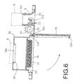
- FIG. 6 is a side cross-sectional view of the faceplate of a blower for an air conditioner in the present invention, showing the second preferred embodiment in operation;
- FIG. 7 is an exploded perspective view of the faceplate of a blower for an air conditioner in the present invention, showing the construction of a third preferred embodiment
- FIG. 8 is an exploded perspective view of the faceplate of a blower for an air conditioner in the present invention, showing the construction of a fourth preferred embodiment
- FIG. 9 is an exploded perspective view of the faceplate of a blower for an air conditioner in the present invention, showing the construction of a fifth preferred embodiment
- FIG. 10 is an exploded perspective view of the faceplate of a blower for an air conditioner in the present invention, showing the construction of a sixth preferred embodiment
- FIG. 11 is a schematic view of the faceplate of a blower for an air conditioner in the present invention, showing the faceplate is installed on a ceiling formed with steel frames;
- FIG. 12 is a schematic view of the faceplate of a blower for an air conditioner in the present invention, showing one construction of the faceplate provided with at least one wind outlet; and,
- FIG. 13 is a schematic view of the faceplate of a blower for an air conditioner in the present invention, showing another construction of the faceplate provided with at least one wind outlet.
- a first preferred embodiment of a faceplate of a blower for an air conditioner in the present invention includes a faceplate 2 and a driving device 3 as main components.
- the faceplate 2 is juxtaposed with at least one wind outlet 20 and at least one wind inlet 21 .
- a wind-out windpipe base 201 is disposed on each of the wind outlets 20 for being covered with a windpipe 6 to blow air out, as shown in FIG. 4 .
- Two through holes 200 are respectively disposed in both sidewalls of each of the wind outlets 20 for being pivoted and combined with a swing member 22 .
- the swing member 22 driven by the driving device 3 has two pivot journals 220 outwardly protruded at both sidewalls of the swing member 22 for corresponding to the two through holes 200 of the wind outlet 20 and a plurality of insert grooves 224 disposed in a plate body of the swing member 22 .
- One of the two pivot journals 220 is provided with an insert hole 221 for being combined with the driving device 3 .
- a plurality of leaves 222 whose turning direction is adjustable are arranged on the plate body of the swing member 22 .
- Each of the leaves 222 has an insert rod 223 protruded at one side for being inserted into and pivoted with each of the insert grooves 224 and a stub rod 225 disposed therein.
- a connecting rod 226 connected with the leaves 222 is provided with retaining rings 227 for being correspondingly engaged with the stub rods 225 of the leaves 222 , by which the leaves 222 are capable of being conveniently turned to different directions so as to adjust the wind-blowing direction of the wind outlet 20 .
- a motor seat 23 disposed proximate one side of the wind outlet 20 is capable of being mounted with a motor 30 of the driving device 3 , by which the swing member 22 can automatically swing back and forth with oscillating movements under the driving of the driving device 3 to adjust the wind-blowing angle of the leaves 222 to increase blowing stroke. Therefore, the blowing area is capable of being expanded by the turning of the leaves 222 to adjust blowing direction of the wind outlet 20 and by the oscillating movements of the swing member 22 to adjust wind-blowing angle.
- a conveniently changeable filter net 24 and a detachable grille 25 are disposed in the wind inlet 21 , as shown in FIGS. 2 and 4.
- At least one hook member 250 disposed in one sidewall of the grille 25 is capable of being correspondingly hooked onto at least one groove 210 disposed in an inner wall of one side of one of the wind inlets 21 ;
- at least one elastic-retaining member 251 disposed in the other sidewall of the grille 25 is capable of being correspondingly engaged into at least one engagement hole 211 disposed in the other side of the wind inlet 21 .
- the driving device 3 connected with the swing member 22 has a motor 30 capable of being screwed to the motor seat 23 in position and whose axle 31 is outwardly protruded for being pivoted with a driving member 32 .
- An outer end of the driving member 32 is combined with one end of a transmission rod 33 whose the other end is combined with one side of an oscillating follower 34 .
- the other side of the oscillating follower 34 is protruded with a projecting rod 34 for being inserted into and combined with the insert hole 221 of the swing member 22 , by which the driving device 3 is constructed to drive the swing member 22 to automatically swing back and forth with oscillating movements.
- FIGS. 2 to 4 In assembling and using, referring to FIGS. 2 to 4 , firstly combine the filter net 24 and the grille 25 onto the wind inlet 21 .
- the grille 25 is hooked onto the wind inlet 21 and is capable of being held to the faceplate 2 in a suspended way of allowing one side of the grille 25 to be removed from the faceplate 2 , as shown in FIG. 4 .
- a second preferred embodiment of the faceplate of a blower for an air conditioner in the present invention includes a faceplate 2 and a driving device 3 as main components.
- the faceplate 2 is juxtaposed with at least one wind outlet 20 and at least one wind inlet 21 .
- a wind-out windpipe base 201 disposed on each of the wind outlets 20 is covered with a windpipe 6 .
- a swing member 22 is pivoted in the wind outlet 20 and is driven by the driving device 3 .
- a plurality of leaves 222 whose turning direction is adjustable are arranged on a plate body of the swing member 22 and are conveniently turned to different directions so as to adjust the blowing direction of the wind outlet 20 .
- a motor seat 23 disposed proximate one side of the wind outlet 20 is capable of being mounted with a motor 30 of the driving device 3 .
- a conveniently changeable filter net 24 and a detachable grille 25 are disposed in the wind inlet 21 , as shown in FIG. 6 .
- At least one hook member 250 disposed in one sidewall of the grille 25 is capable of being correspondingly hooked onto at least one groove 210 disposed in an inner wall of one side of one of the wind inlets 21 ;
- at least one elastic-retaining member 251 disposed in the other sidewall of the grille 25 is capable of being correspondingly engaged into at least one engagement hole 211 disposed in the other side of the wind inlet 21 .
- a wind-in windpipe base 26 integrated with each of the wind inlets 21 of the faceplate 2 is provided with at least one wind-in hole 260 whose circumference is disposed with an engagement edge 261 for convenience of being engaged with a windpipe 6 to suck air in.
- a third preferred embodiment of the faceplate of a blower for an air conditioner in the present invention includes a faceplate 2 and a driving device 3 as main components.
- the faceplate 2 is juxtaposed with at least one wind outlet 20 and at least one wind inlet 21 .
- a swing member 22 is pivoted in the wind outlet 20 and is driven by the driving device 3 .
- a wind-out windpipe base 201 is disposed on each of the wind outlets 20 for being covered with a windpipe 6 to blow air out.
- a conveniently changeable filter net 24 and a detachable grille 25 are disposed in the wind inlet 21 .
- a detachable box-like wind-in windpipe base 4 is capable of being combined with each of the wind inlets 21 of the faceplate 2 by correspondingly aligning a plurality of screw holes 42 of the wind-in windpipe base 4 to a plurality of combining holes 27 of the wind inlet 21 and using combining members 40 to screw the combining holes 27 and the screw holes 42 together in position from a bottom of the wind inlet 21 .
- the wind-in windpipe base 4 has at least one wind-in hole 41 whose circumference is disposed with an engagement edge 410 for convenience of being engaged with a windpipe 6 to suck air in.
- a fourth preferred embodiment of the faceplate of a blower for an air conditioner in the present invention includes a faceplate 2 and a driving device 3 as main components.
- the faceplate 2 is juxtaposed with at least one wind outlet 20 and at least one wind inlet 21 .
- a swing member 22 is pivoted in the wind outlet 20 and is driven by the driving device 3 .
- a wind-out windpipe base 201 is disposed on each of the wind outlets 20 for being covered with a windpipe 6 to blow air out.
- a conveniently changeable filter net 24 and a detachable grille 25 are disposed in the wind inlet 21 .
- a detachable plate-like wind-in windpipe base 5 is capable of being combined with each of the wind inlets 21 of the faceplate 2 by correspondingly aligning a plurality of screw holes 52 of the wind-in windpipe base 5 to a plurality of combining holes 27 of the wind inlet 21 and using combining members 50 to screw the combining holes 27 and the screw holes 52 together in position from a bottom of the wind inlet 21 .
- the wind-in windpipe base 5 has at least one wind-in hole 51 whose circumference is disposed with an engagement edge 510 for convenience of being engaged with a windpipe 6 to suck air in.
- a fifth preferred embodiment of the faceplate of a blower for an air conditioner in the present invention includes a faceplate 2 and a driving device 3 as main components.
- the faceplate 2 is juxtaposed with at least one wind outlet 20 and at least one wind inlet 21 .
- a swing member 22 is pivoted in the wind outlet 20 and is driven by the driving device 3 .
- a conveniently changeable filter net 24 and a detachable grille are disposed in the wind inlet 21 .
- a detachable wind-out windpipe base 7 is capable of being combined with each of the wind outlets 20 of the faceplate 2 by correspondingly aligning a plurality of through holes 72 of the wind-out windpipe base 7 to a plurality of combining holes 28 of the wind outlet 20 and using combining members 70 to screw the through holes 72 and the combining holes 28 together in position.
- the wind-out windpipe base 7 has at least one wind-out hole 71 for convenience of being covered with a windpipe 6 to blow air out.
- a sixth preferred embodiment of the faceplate of a blower for an air conditioner in the present invention includes a faceplate 2 and a driving device 3 as main components.
- the faceplate 2 is juxtaposed with at least one wind outlet 20 and at least one wind inlet 21 .
- a swing member 22 is pivoted in the wind outlet 20 and is driven by the driving device 3 .
- a conveniently changeable filter net 24 and a detachable grille 25 are disposed in the wind inlet 21 .
- the faceplate 2 is capable of being combined with an integral windpipe base assembly 8 provided with at least one wind-out hole 80 and at least one wind-in hole 81 for corresponding to each of the wind outlets 20 and each of the wind inlets 21 of the faceplate 2 .
- Each of the wind-out holes 80 is capable of being covered with a windpipe 6 to blow air out.
- Each of the wind-in holes 81 is provided with an engagement edge 810 for being engaged with a windpipe 6 to suck air out.
- the integral windpipe base assembly 8 is capable of being combined with the faceplate 2 by correspondingly aligning a plurality of through holes 82 disposed around the circumference of the integral windpipe base assembly 8 to a plurality of combining holes 27 and combining holes 28 of the faceplate 2 and using screw members 83 to screw the through holes 82 , the combining holes 27 and the combining holes 28 together in position.
- the faceplate 2 is designed to be juxtaposed with at least one wind outlet 20 so as to construct a multi-blowing faceplate, as shown in FIGS. 11 to 13 .
Landscapes
- Engineering & Computer Science (AREA)
- Chemical & Material Sciences (AREA)
- Combustion & Propulsion (AREA)
- Mechanical Engineering (AREA)
- General Engineering & Computer Science (AREA)
- Air Filters, Heat-Exchange Apparatuses, And Housings Of Air-Conditioning Units (AREA)
- Duct Arrangements (AREA)
Abstract
A faceplate of a blower for an air conditioner in the present invention relates to a faceplate juxtaposed with at least one wind outlet and at least one wind inlet, wherein each of the wind outlets and each of the wind inlets are respectively disposed with a wind-out windpipe base and a wind-in windpipe base for being connected with windpipes; each of the wind outlets is provided with a swing member for adjusting blowing direction; each of the wind inlets is provided with a detachable filter net and a detachable grille, by which a combination of said components described above provides said faceplate with functions of wind-blowing, wind-suction and blowing-direction adjustment to achieve an optimum effect in air circulation.
Description
1. Field of the Invention
This invention relates to a faceplate of a blower for an air conditioner, particularly to one juxtaposed with at least one wind outlet and at least one wind inlet, wherein each of the wind outlets is pivoted with a swing member, by which a combination of the components described above provides the faceplate with functions of wind-blowing, wind-suction and blowing-direction adjustment.
2. Description of the Prior Art
A known conventional air conditioning system, as shown in FIG. 1, has many wind-out faceplates 11 and wind-in faceplates 12 respectively installed on the ceiling formed with steel frames 10 and uses windpipes to connect the wind-out faceplates 11 with a main machine to blow air out. Each of the wind-in faceplates 12 is installed around each of the wind-out faceplates 11 and adhesived with a filter net. This kind of design is very inconvenient in repairing or cleaning work because the whole wind-in faceplate 12 and the whole wind-out faceplate 11 are required to be disassembled for checking or repairing components in the interior of the known air conditioning system. Moreover, it is a very heavy work for repairmen to disassemble so many wind-in faceplates 12 and wind-out faceplates 11 in repairing or cleaning work, which is also very troublesome and time-consuming.
It is one primary object of the present invention to offer a faceplate of a blower for an air conditioner capable of blowing air out and sucking air in at the same time.
It is another object of the present invention to offer a faceplate of a blower for an air conditioner provided with a function of blowing-direction adjustment.
It is one further object of the present invention to offer a faceplate of a blower for an air conditioner provided with a filter net and a grille that are convenient for assembling and disassembling, and being rapid in repairing or cleaning work.
One primary feature of the invention is to provide a faceplate of a blower for an air conditioner juxtaposed with at least one wind outlet and at least one wind inlet, wherein each of the wind outlets is disposed with a wind-out windpipe base provided with at least one wind-out hole for being covered with a windpipe to blow air out.
One another feature of the invention is to provide a faceplate of a blower for an air conditioner juxtaposed with at least one wind outlet and at least one wind inlet, wherein each of the wind outlets is disposed with a wind-out windpipe base provided with at least one wind-out hole for being covered with a windpipe to blow air out; each of the wind inlets is disposed with a wind-in windpipe base provided with at least one wind-in hole for being engaged with a windpipe to suck air in.
One further feature of the invention is to provide a faceplate of a blower for an air conditioner juxtaposed with at least one wind outlet and at least one wind inlet, wherein the faceplate is combined with an integral windpipe base assembly provided with at least one wind-out hole and at least one wind-in hole for being connected with windpipes to blow air out and suck air in.
This invention will be better understood by referring to the accompanying drawings, wherein:
FIG. 1 is a schematic view of a known conventional air conditioning system, showing an arrangement of wind-out faceplates and wind-in faceplates installed on a ceiling formed with steel frames;
FIG. 2 is an exploded perspective view of a faceplate of a blower for an air conditioner in the present invention, showing the construction of a first preferred embodiment;
FIG. 3 is an exploded perspective view of the faceplate of a blower for an air conditioner in the present invention, showing the construction of a swing member;
FIG. 4 is a side cross-sectional view of the faceplate of a blower for an air conditioner in the present invention, showing the first preferred embodiment in operation;
FIG. 5 is an exploded perspective view of the faceplate of a blower for an air conditioner in the present invention, showing the construction of a second preferred embodiment;
FIG. 6 is a side cross-sectional view of the faceplate of a blower for an air conditioner in the present invention, showing the second preferred embodiment in operation;
FIG. 7 is an exploded perspective view of the faceplate of a blower for an air conditioner in the present invention, showing the construction of a third preferred embodiment;
FIG. 8 is an exploded perspective view of the faceplate of a blower for an air conditioner in the present invention, showing the construction of a fourth preferred embodiment;
FIG. 9 is an exploded perspective view of the faceplate of a blower for an air conditioner in the present invention, showing the construction of a fifth preferred embodiment;
FIG. 10 is an exploded perspective view of the faceplate of a blower for an air conditioner in the present invention, showing the construction of a sixth preferred embodiment;
FIG. 11 is a schematic view of the faceplate of a blower for an air conditioner in the present invention, showing the faceplate is installed on a ceiling formed with steel frames;
FIG. 12 is a schematic view of the faceplate of a blower for an air conditioner in the present invention, showing one construction of the faceplate provided with at least one wind outlet; and,
FIG. 13 is a schematic view of the faceplate of a blower for an air conditioner in the present invention, showing another construction of the faceplate provided with at least one wind outlet.
A first preferred embodiment of a faceplate of a blower for an air conditioner in the present invention, as shown in FIGS. 2 to 4, includes a faceplate 2 and a driving device 3 as main components.
The faceplate 2 is juxtaposed with at least one wind outlet 20 and at least one wind inlet 21. A wind-out windpipe base 201 is disposed on each of the wind outlets 20 for being covered with a windpipe 6 to blow air out, as shown in FIG. 4. Two through holes 200 are respectively disposed in both sidewalls of each of the wind outlets 20 for being pivoted and combined with a swing member 22. The swing member 22 driven by the driving device 3 has two pivot journals 220 outwardly protruded at both sidewalls of the swing member 22 for corresponding to the two through holes 200 of the wind outlet 20 and a plurality of insert grooves 224 disposed in a plate body of the swing member 22. One of the two pivot journals 220 is provided with an insert hole 221 for being combined with the driving device 3. As shown in FIG. 3, a plurality of leaves 222 whose turning direction is adjustable are arranged on the plate body of the swing member 22. Each of the leaves 222 has an insert rod 223 protruded at one side for being inserted into and pivoted with each of the insert grooves 224 and a stub rod 225 disposed therein. A connecting rod 226 connected with the leaves 222 is provided with retaining rings 227 for being correspondingly engaged with the stub rods 225 of the leaves 222, by which the leaves 222 are capable of being conveniently turned to different directions so as to adjust the wind-blowing direction of the wind outlet 20. Inside the faceplate 2, a motor seat 23 disposed proximate one side of the wind outlet 20 is capable of being mounted with a motor 30 of the driving device 3, by which the swing member 22 can automatically swing back and forth with oscillating movements under the driving of the driving device 3 to adjust the wind-blowing angle of the leaves 222 to increase blowing stroke. Therefore, the blowing area is capable of being expanded by the turning of the leaves 222 to adjust blowing direction of the wind outlet 20 and by the oscillating movements of the swing member 22 to adjust wind-blowing angle.
Moreover, a conveniently changeable filter net 24 and a detachable grille 25 are disposed in the wind inlet 21, as shown in FIGS. 2 and 4. At least one hook member 250 disposed in one sidewall of the grille 25 is capable of being correspondingly hooked onto at least one groove 210 disposed in an inner wall of one side of one of the wind inlets 21; at least one elastic-retaining member 251 disposed in the other sidewall of the grille 25 is capable of being correspondingly engaged into at least one engagement hole 211 disposed in the other side of the wind inlet 21.
The driving device 3 connected with the swing member 22 has a motor 30 capable of being screwed to the motor seat 23 in position and whose axle 31 is outwardly protruded for being pivoted with a driving member 32. An outer end of the driving member 32 is combined with one end of a transmission rod 33 whose the other end is combined with one side of an oscillating follower 34. The other side of the oscillating follower 34 is protruded with a projecting rod 34 for being inserted into and combined with the insert hole 221 of the swing member 22, by which the driving device 3 is constructed to drive the swing member 22 to automatically swing back and forth with oscillating movements.
In assembling and using, referring to FIGS. 2 to 4, firstly combine the filter net 24 and the grille 25 onto the wind inlet 21. The grille 25 is hooked onto the wind inlet 21 and is capable of being held to the faceplate 2 in a suspended way of allowing one side of the grille 25 to be removed from the faceplate 2, as shown in FIG. 4. Secondly, extend the two pivot journals 220 that are outwardly protruded at both sidewalls of the swing member 22 of the faceplate 2 respectively through the two through holes 200 that are disposed in both sidewalls of the wind outlet 20 to make the 20 insert hole 221 of one of the two pivot journals 220 aligned with and inserted by the projecting rod 340 of the oscillating rod 34 of the driving device 3. Thirdly, orderly connect the transmission rod 33 and the driving member 32 from the outer surface of the oscillating rod 34 to the axle 31 of the motor, by which the driving device 3 is constructed to drive the swing member 22 that is pivoted inside the wind outlet 20 to automatically swing back and forth with oscillating movements. Finally, cover a windpipe 6 on the wind-out windpipe base 201 of the wind-out hole 20 in position. With a combination of the components described above provides the faceplate of a blower for an air conditioner in the present invention with functions of wind-blowing as well as wind-suction, and with convenience for repairmen to check and repair components in the interior of the faceplate 2.
A second preferred embodiment of the faceplate of a blower for an air conditioner in the present invention, as shown in FIGS. 5 and 6, includes a faceplate 2 and a driving device 3 as main components.
Like the first preferred embodiment, the faceplate 2 is juxtaposed with at least one wind outlet 20 and at least one wind inlet 21. A wind-out windpipe base 201 disposed on each of the wind outlets 20 is covered with a windpipe 6. A swing member 22 is pivoted in the wind outlet 20 and is driven by the driving device 3. A plurality of leaves 222 whose turning direction is adjustable are arranged on a plate body of the swing member 22 and are conveniently turned to different directions so as to adjust the blowing direction of the wind outlet 20. Inside the faceplate 2, a motor seat 23 disposed proximate one side of the wind outlet 20 is capable of being mounted with a motor 30 of the driving device 3. A conveniently changeable filter net 24 and a detachable grille 25 are disposed in the wind inlet 21, as shown in FIG. 6. At least one hook member 250 disposed in one sidewall of the grille 25 is capable of being correspondingly hooked onto at least one groove 210 disposed in an inner wall of one side of one of the wind inlets 21; at least one elastic-retaining member 251 disposed in the other sidewall of the grille 25 is capable of being correspondingly engaged into at least one engagement hole 211 disposed in the other side of the wind inlet 21.
Furthermore, a wind-in windpipe base 26 integrated with each of the wind inlets 21 of the faceplate 2 is provided with at least one wind-in hole 260 whose circumference is disposed with an engagement edge 261 for convenience of being engaged with a windpipe 6 to suck air in.
A third preferred embodiment of the faceplate of a blower for an air conditioner in the present invention, as shown in FIG. 7, includes a faceplate 2 and a driving device 3 as main components.
Like the first preferred embodiment, the faceplate 2 is juxtaposed with at least one wind outlet 20 and at least one wind inlet 21. A swing member 22 is pivoted in the wind outlet 20 and is driven by the driving device 3. A wind-out windpipe base 201 is disposed on each of the wind outlets 20 for being covered with a windpipe 6 to blow air out. A conveniently changeable filter net 24 and a detachable grille 25 are disposed in the wind inlet 21.
Furthermore, a detachable box-like wind-in windpipe base 4 is capable of being combined with each of the wind inlets 21 of the faceplate 2 by correspondingly aligning a plurality of screw holes 42 of the wind-in windpipe base 4 to a plurality of combining holes 27 of the wind inlet 21 and using combining members 40 to screw the combining holes 27 and the screw holes 42 together in position from a bottom of the wind inlet 21. The wind-in windpipe base 4 has at least one wind-in hole 41 whose circumference is disposed with an engagement edge 410 for convenience of being engaged with a windpipe 6 to suck air in.
A fourth preferred embodiment of the faceplate of a blower for an air conditioner in the present invention, as shown in FIG. 8, includes a faceplate 2 and a driving device 3 as main components.
Like the first preferred embodiment, the faceplate 2 is juxtaposed with at least one wind outlet 20 and at least one wind inlet 21. A swing member 22 is pivoted in the wind outlet 20 and is driven by the driving device 3. A wind-out windpipe base 201 is disposed on each of the wind outlets 20 for being covered with a windpipe 6 to blow air out. A conveniently changeable filter net 24 and a detachable grille 25 are disposed in the wind inlet 21.
Furthermore, a detachable plate-like wind-in windpipe base 5 is capable of being combined with each of the wind inlets 21 of the faceplate 2 by correspondingly aligning a plurality of screw holes 52 of the wind-in windpipe base 5 to a plurality of combining holes 27 of the wind inlet 21 and using combining members 50 to screw the combining holes 27 and the screw holes 52 together in position from a bottom of the wind inlet 21. The wind-in windpipe base 5 has at least one wind-in hole 51 whose circumference is disposed with an engagement edge 510 for convenience of being engaged with a windpipe 6 to suck air in.
A fifth preferred embodiment of the faceplate of a blower for an air conditioner in the present invention, as shown in FIG. 9, includes a faceplate 2 and a driving device 3 as main components.
Like the first preferred embodiment, the faceplate 2 is juxtaposed with at least one wind outlet 20 and at least one wind inlet 21. A swing member 22 is pivoted in the wind outlet 20 and is driven by the driving device 3. A conveniently changeable filter net 24 and a detachable grille are disposed in the wind inlet 21.
Furthermore, a detachable wind-out windpipe base 7 is capable of being combined with each of the wind outlets 20 of the faceplate 2 by correspondingly aligning a plurality of through holes 72 of the wind-out windpipe base 7 to a plurality of combining holes 28 of the wind outlet 20 and using combining members 70 to screw the through holes 72 and the combining holes 28 together in position. The wind-out windpipe base 7 has at least one wind-out hole 71 for convenience of being covered with a windpipe 6 to blow air out.
A sixth preferred embodiment of the faceplate of a blower for an air conditioner in the present invention, as shown in FIG. 10, includes a faceplate 2 and a driving device 3 as main components.
Like the first preferred embodiment, the faceplate 2 is juxtaposed with at least one wind outlet 20 and at least one wind inlet 21. A swing member 22 is pivoted in the wind outlet 20 and is driven by the driving device 3. A conveniently changeable filter net 24 and a detachable grille 25 are disposed in the wind inlet 21.
Furthermore, the faceplate 2 is capable of being combined with an integral windpipe base assembly 8 provided with at least one wind-out hole 80 and at least one wind-in hole 81 for corresponding to each of the wind outlets 20 and each of the wind inlets 21 of the faceplate 2. Each of the wind-out holes 80 is capable of being covered with a windpipe 6 to blow air out. Each of the wind-in holes 81 is provided with an engagement edge 810 for being engaged with a windpipe 6 to suck air out. The integral windpipe base assembly 8 is capable of being combined with the faceplate 2 by correspondingly aligning a plurality of through holes 82 disposed around the circumference of the integral windpipe base assembly 8 to a plurality of combining holes 27 and combining holes 28 of the faceplate 2 and using screw members 83 to screw the through holes 82, the combining holes 27 and the combining holes 28 together in position.
Besides, among the components described above, all wall surfaces of the wind outlets 20 of the faceplate 2 and extension portions of the wind outlets 20 for being connected with windpipes 6 are spread with temperature-insulting materials 9.
Moreover, the faceplate 2 is designed to be juxtaposed with at least one wind outlet 20 so as to construct a multi-blowing faceplate, as shown in FIGS. 11 to 13.
While the preferred embodiments of the invention have been described above, it will be recognized and understood that various modifications may be made therein and the appended claims are intended to cover all such modifications that may fall within the spirit and scope of the invention.
Claims (5)
1. A faceplate of a blower for an air conditioner comprising:
a faceplate juxtaposed with at least one wind outlet and at least one wind inlet, wherein each said wind outlet is disposed with a wind-out windpipe base provided with at least one wind-out hole for being covered with a windpipe to blow air out; and,
wherein each said wind inlet is provided with a detachable grille; at least one groove disposed in an inner wall of one side of each said wind inlet is capable of corresponding to at least one hook member disposed in one sidewall of said grille; at least one engagement hole disposed in another side of said wind inlet is capable of corresponding to at least one elastic-retaining member disposed in the other sidewall of said grille; and,
whereby said grille is conveniently hooked onto said wind inlet and is capable of being held to said faceplate in a suspended way of allowing one side of said grille to be removed from said faceplate,
whereby a combination of said components described above provides said faceplate with functions of wind-blowing and wind-suction.
2. A faceplate of a blower for an air conditioner comprising:
a faceplate juxtaposed with at least one wind outlet and at least one wind inlet, wherein each said wind outlet is disposed with a wind-out windpipe base provided with at least one wind-out hole for being covered with a windpipe to blow air out; each said wind inlet is disposed with a wind-in windpipe base provided with at least one wind-in hole for being engaged with a windpipe to suck air in; and,
wherein each said wind inlet is provided with a detachable grille; at least one groove disposed in an inner wall of one side of each said wind inlet is capable of corresponding to at least one hook member disposed in one sidewall of said grille; at least one engagement hole disposed in another side of said wind inlet is capable of corresponding to at least one elastic-retaining member disposed in the other sidewall of said grille; and,
whereby a combination of said components described above provides said faceplate with functions of wind-blowing and wind-suction.
3. A faceplate of a blower for an air conditioner comprising:
a faceplate juxtaposed with at least one wind outlet and at least one wind inlet, wherein said faceplate is combined with an integral windpipe base assembly provided with at least one wind-out hole and at least one wind-in hole for being connected with windpipes to blow air out and suck air in; and
wherein each said wind inlet is provided with a detachable grille; at least one groove disposed in an inner wall of one side of each said wind inlet is capable of corresponding to at least one hook member disposed in one sidewall of said grille; at least one engagement hole disposed in another side of said wind inlet is capable of corresponding to at least one elastic-retaining member disposed in the other sidewall of said grille; and.
4. The faceplate of a blower for an air conditioner as claimed in claim 2 , wherein an engagement edge is formed in circumference of each said wind-in hole of said wind-in windpipe base for convenience of being engaged with a windpipe.
5. The faceplate of a blower for an air conditioner as claimed in claim 3 , wherein an engagement edge is formed in circumference of each said wind-in hole of said integral windpipe base assembly for convenience of being engaged with a windpipe.
Priority Applications (6)
| Application Number | Priority Date | Filing Date | Title |
|---|---|---|---|
| US10/029,920 US6488578B1 (en) | 2001-12-31 | 2001-12-31 | Faceplate of a blower for an air conditioner |
| EP02000477A EP1327833A1 (en) | 2001-12-31 | 2002-01-08 | Faceplate of a blower for an air conditioner |
| ZA200200217A ZA200200217B (en) | 2001-12-31 | 2002-01-10 | Faceplate of a blower for an air container. |
| JP2002005480A JP2003207198A (en) | 2001-12-31 | 2002-01-15 | Face panel structure for air-conditioning fan |
| CA002367873A CA2367873A1 (en) | 2001-12-31 | 2002-01-15 | Faceplate of a blower for an air conditioner |
| BR0200123-3A BR0200123A (en) | 2001-12-31 | 2002-01-18 | Faceplate of a blower for an air conditioner |
Applications Claiming Priority (6)
| Application Number | Priority Date | Filing Date | Title |
|---|---|---|---|
| US10/029,920 US6488578B1 (en) | 2001-12-31 | 2001-12-31 | Faceplate of a blower for an air conditioner |
| EP02000477A EP1327833A1 (en) | 2001-12-31 | 2002-01-08 | Faceplate of a blower for an air conditioner |
| ZA200200217A ZA200200217B (en) | 2001-12-31 | 2002-01-10 | Faceplate of a blower for an air container. |
| JP2002005480A JP2003207198A (en) | 2001-12-31 | 2002-01-15 | Face panel structure for air-conditioning fan |
| CA002367873A CA2367873A1 (en) | 2001-12-31 | 2002-01-15 | Faceplate of a blower for an air conditioner |
| BR0200123-3A BR0200123A (en) | 2001-12-31 | 2002-01-18 | Faceplate of a blower for an air conditioner |
Publications (1)
| Publication Number | Publication Date |
|---|---|
| US6488578B1 true US6488578B1 (en) | 2002-12-03 |
Family
ID=32180784
Family Applications (1)
| Application Number | Title | Priority Date | Filing Date |
|---|---|---|---|
| US10/029,920 Expired - Fee Related US6488578B1 (en) | 2001-12-31 | 2001-12-31 | Faceplate of a blower for an air conditioner |
Country Status (6)
| Country | Link |
|---|---|
| US (1) | US6488578B1 (en) |
| EP (1) | EP1327833A1 (en) |
| JP (1) | JP2003207198A (en) |
| BR (1) | BR0200123A (en) |
| CA (1) | CA2367873A1 (en) |
| ZA (1) | ZA200200217B (en) |
Cited By (9)
| Publication number | Priority date | Publication date | Assignee | Title |
|---|---|---|---|---|
| SG115441A1 (en) * | 2002-01-08 | 2005-10-28 | Kuo Chin Sheng | Faceplate of a blower for an air conditioner |
| US20070037508A1 (en) * | 2005-08-15 | 2007-02-15 | Ruberg Daniel C | Air register cover assembly |
| US20120015599A1 (en) * | 2009-03-27 | 2012-01-19 | Yoshiteru Nouchi | Air conditioner, casing, and decorative panel |
| US20150159910A1 (en) * | 2013-12-10 | 2015-06-11 | Delta Electronics, Inc. | Ventilation fan |
| US20170307250A1 (en) * | 2015-01-13 | 2017-10-26 | Knauf Gips Kg | Air outlet for a ventilation device |
| CN113648731A (en) * | 2021-08-27 | 2021-11-16 | 蚌埠市东泰环保科技有限公司 | Air dust removal tuber pipe for environmental protection |
| US11384955B2 (en) * | 2017-02-01 | 2022-07-12 | Mitsubishi Electric Corporation | Indoor unit for air-conditioning apparatus, and air-conditioning apparatus |
| US12146679B1 (en) | 2023-06-07 | 2024-11-19 | Filtrex Pure Air, Llc | Toolless installation of vent assembly |
| US12313284B2 (en) | 2023-06-07 | 2025-05-27 | Filtrex Pure Air, Llc | Toolless installation and cleaning of vent assembly |
Families Citing this family (3)
| Publication number | Priority date | Publication date | Assignee | Title |
|---|---|---|---|---|
| KR20030062522A (en) * | 2002-01-17 | 2003-07-28 | 큐오 친-생 | Faceplate of a blower for an air conditioner |
| SE540427C2 (en) | 2015-09-17 | 2018-09-11 | Flaektgroup Sweden Ab | Device and method for controlling a supply air flow at a comfort cassette |
| CN110631151B (en) * | 2019-09-16 | 2024-08-02 | 广东爱美信电器有限公司 | Air purifier with multiple air channels |
Citations (3)
| Publication number | Priority date | Publication date | Assignee | Title |
|---|---|---|---|---|
| US2185919A (en) * | 1938-01-15 | 1940-01-02 | Franz J Kurth | Ventilating device |
| US3885462A (en) * | 1972-11-13 | 1975-05-27 | Gullfiber Ab | Device to condition rooms |
| US5251461A (en) * | 1992-09-18 | 1993-10-12 | Carrier Corporation | Grille for packaged terminal air conditioner |
Family Cites Families (5)
| Publication number | Priority date | Publication date | Assignee | Title |
|---|---|---|---|---|
| JPH02233920A (en) * | 1989-03-03 | 1990-09-17 | Sanyo Electric Co Ltd | Ceiling-embedded type air-conditioning device |
| JPH0875234A (en) * | 1994-09-06 | 1996-03-19 | Daikin Ind Ltd | Air conditioner outlet unit |
| US5934362A (en) * | 1997-01-21 | 1999-08-10 | Tele-Flow, Inc. | Combination bath fan, register box, air conditioning and heating boot |
| US6260375B1 (en) * | 2000-06-09 | 2001-07-17 | Chin-Sheng Kuo | Air conditioner blowing cool air to many directions |
| DE20103908U1 (en) * | 2001-03-06 | 2001-06-21 | Kuo, Chin-Sheng, Kuan-Miao, Tainan | Wind vent base device of a blower for an air conditioner |
-
2001
- 2001-12-31 US US10/029,920 patent/US6488578B1/en not_active Expired - Fee Related
-
2002
- 2002-01-08 EP EP02000477A patent/EP1327833A1/en not_active Withdrawn
- 2002-01-10 ZA ZA200200217A patent/ZA200200217B/en unknown
- 2002-01-15 JP JP2002005480A patent/JP2003207198A/en active Pending
- 2002-01-15 CA CA002367873A patent/CA2367873A1/en not_active Abandoned
- 2002-01-18 BR BR0200123-3A patent/BR0200123A/en not_active IP Right Cessation
Patent Citations (3)
| Publication number | Priority date | Publication date | Assignee | Title |
|---|---|---|---|---|
| US2185919A (en) * | 1938-01-15 | 1940-01-02 | Franz J Kurth | Ventilating device |
| US3885462A (en) * | 1972-11-13 | 1975-05-27 | Gullfiber Ab | Device to condition rooms |
| US5251461A (en) * | 1992-09-18 | 1993-10-12 | Carrier Corporation | Grille for packaged terminal air conditioner |
Cited By (11)
| Publication number | Priority date | Publication date | Assignee | Title |
|---|---|---|---|---|
| SG115441A1 (en) * | 2002-01-08 | 2005-10-28 | Kuo Chin Sheng | Faceplate of a blower for an air conditioner |
| US20070037508A1 (en) * | 2005-08-15 | 2007-02-15 | Ruberg Daniel C | Air register cover assembly |
| US20120015599A1 (en) * | 2009-03-27 | 2012-01-19 | Yoshiteru Nouchi | Air conditioner, casing, and decorative panel |
| US20150159910A1 (en) * | 2013-12-10 | 2015-06-11 | Delta Electronics, Inc. | Ventilation fan |
| US10352584B2 (en) * | 2013-12-10 | 2019-07-16 | Delta Electronics, Inc. | Ventilation fan |
| US20170307250A1 (en) * | 2015-01-13 | 2017-10-26 | Knauf Gips Kg | Air outlet for a ventilation device |
| US11384955B2 (en) * | 2017-02-01 | 2022-07-12 | Mitsubishi Electric Corporation | Indoor unit for air-conditioning apparatus, and air-conditioning apparatus |
| CN113648731A (en) * | 2021-08-27 | 2021-11-16 | 蚌埠市东泰环保科技有限公司 | Air dust removal tuber pipe for environmental protection |
| US12146679B1 (en) | 2023-06-07 | 2024-11-19 | Filtrex Pure Air, Llc | Toolless installation of vent assembly |
| US12313284B2 (en) | 2023-06-07 | 2025-05-27 | Filtrex Pure Air, Llc | Toolless installation and cleaning of vent assembly |
| US12372269B2 (en) | 2023-06-07 | 2025-07-29 | Filtrex Pure Air, Llc | Toolless installation of vent assembly |
Also Published As
| Publication number | Publication date |
|---|---|
| JP2003207198A (en) | 2003-07-25 |
| CA2367873A1 (en) | 2003-07-15 |
| BR0200123A (en) | 2003-10-21 |
| EP1327833A1 (en) | 2003-07-16 |
| ZA200200217B (en) | 2002-09-25 |
Similar Documents
| Publication | Publication Date | Title |
|---|---|---|
| US6488578B1 (en) | Faceplate of a blower for an air conditioner | |
| US6101829A (en) | Air conditioning apparatus | |
| JP5113639B2 (en) | Gas flow adjusting mechanism and air conditioner | |
| US20030092373A1 (en) | Faceplate of a blower for an air conditioner | |
| US6260375B1 (en) | Air conditioner blowing cool air to many directions | |
| CN106642359A (en) | Louver blade for air-conditioner indoor unit, louver component and air-conditioner indoor unit | |
| US20060260783A1 (en) | Center mounting type air conditioner for vehicle | |
| US11254184B2 (en) | Canopy downdraft fan assembly | |
| CN108954536A (en) | Air interchanger and air conditioner with same | |
| CA2308138C (en) | Air conditioner air directing apparatus | |
| AU1196802A (en) | Faceplate of a blower for an air conditioner | |
| EP2163831B1 (en) | Air conditioner | |
| JP2000039209A (en) | Ceiling-mounted air conditioner | |
| AU2001100344A4 (en) | Faceplate of a blower for an air conditioner | |
| KR20090020962A (en) | Duct type air conditioner | |
| KR100471437B1 (en) | A fan housing's installing structure of the duct type air-conditioner | |
| JP6867861B2 (en) | Outdoor unit of air conditioner | |
| US20040069449A1 (en) | Blower for an air conditioner | |
| CN106274761B (en) | Vehicle seat and driver's cabin | |
| KR20030062522A (en) | Faceplate of a blower for an air conditioner | |
| KR100461651B1 (en) | Motor Mount For Outside Machine Of Air Conditioner | |
| JP4042521B2 (en) | Ventilation grill | |
| KR100749061B1 (en) | Air conditioner | |
| KR20030035118A (en) | A fan-housing assembly of the duct type air-conditioner | |
| KR100337904B1 (en) | Inlet grill structure with ribs for supporting and determination of assembly position |
Legal Events
| Date | Code | Title | Description |
|---|---|---|---|
| REMI | Maintenance fee reminder mailed | ||
| LAPS | Lapse for failure to pay maintenance fees | ||
| STCH | Information on status: patent discontinuation |
Free format text: PATENT EXPIRED DUE TO NONPAYMENT OF MAINTENANCE FEES UNDER 37 CFR 1.362 |
|
| FP | Expired due to failure to pay maintenance fee |
Effective date: 20061203 |