US6484802B1 - Downhole scraper assembly - Google Patents
Downhole scraper assembly Download PDFInfo
- Publication number
- US6484802B1 US6484802B1 US09/762,252 US76225201A US6484802B1 US 6484802 B1 US6484802 B1 US 6484802B1 US 76225201 A US76225201 A US 76225201A US 6484802 B1 US6484802 B1 US 6484802B1
- Authority
- US
- United States
- Prior art keywords
- scraper
- scraper element
- assembly
- wellbore
- scraper assembly
- Prior art date
- Legal status (The legal status is an assumption and is not a legal conclusion. Google has not performed a legal analysis and makes no representation as to the accuracy of the status listed.)
- Expired - Lifetime
Links
Images


Classifications
-
- E—FIXED CONSTRUCTIONS
- E21—EARTH OR ROCK DRILLING; MINING
- E21B—EARTH OR ROCK DRILLING; OBTAINING OIL, GAS, WATER, SOLUBLE OR MELTABLE MATERIALS OR A SLURRY OF MINERALS FROM WELLS
- E21B37/00—Methods or apparatus for cleaning boreholes or wells
- E21B37/02—Scrapers specially adapted therefor
Definitions
- This invention relates to apparatus for scraping the inner surface of a wellbore.
- This invention relates to apparatus for scraping the inner surface of a wellbore.
- FIG. 1 of the accompanying drawings A conventional scraper assembly is shown in FIG. 1 of the accompanying drawings.
- a prior art assembly incorporates a plurality of scraper elements mounted with compression springs about a mandrel.
- the scraper elements are arranged in such a way as to ensure full circumferential scraping of the casing when the assembly is run downhole without rotation. In the assembly of FIG. 1, this is achieved with the use of three longitudinally spaced pairs of scraper elements which are circumferentially offset relative to each other. A small degree of circumferential overlap is provided between the pairs of scraper elements so as to ensure uninterrupted circumferential scraping.
- Each scraper element covers approximately 60° of the circumference of wellbore casing to be scraped.
- the scraper elements of each pair are located on opposite sides of the mandrel and are biased radially into scraping engagement with the wellbore casing by means of compression springs.
- a number of problems are associated with the conventional scraper assembly described above. Firstly, the assembly is undesirably long due to the longitudinal spacing of the scraper element pairs. This longitudinal spacing is necessitated by the spring biasing system employed and the need to circumferentially overlap the pairs of scraper elements so as to ensure full scraping of the wellbore. Secondly, the multiple scraper element arrangement results in an item of downhole equipment which is relatively complex and expensive to manufacture.
- the present invention provides a scraper assembly for use in a wellbore, the scraper assembly comprising a scraper element incorporating: a generally cylindrical member defined by a wall having a slot extending through the wall thickness; and at least one tooth member provided on the outer surface of the wall for scraping engagement with a wellbore, the scraper assembly being characterised in that the slot extends helically along the length of the cylindrical member.
- the scraper assembly of the present invention may thereby incorporate only one scraper element to ensure full circumferential scraping.
- the slot in the wall of the generally cylindrical member allows for radial deflection of the scraper element as the at least one tooth member engages the wellbore.
- the scraper element is sized so that the maximum diameter of the scraper element (as determined by the at least one tooth member), when in its relaxed state prior to use, is greater than the inner diameter of the wellbore casing to be scraped.
- the slot allows the radial deflection without undesirable buckling of the scraper element.
- the arrangement is such that the deflection is elastic. This results in the at least one tooth member applying an appropriate radial force on the wellbore casing during the scraping process.
- tooth members are provided on the outer surface of the wall for scraping engagement with a wellbore. It is desirable for the or each tooth member to extend helically about the longitudinal axis of the scraper element. Furthermore, it is preferable for the slot to extend from one end of the generally cylindrical member to the opposite end of the generally cylindrical member. The slot may also extend helically along the length of the generally cylindrical member. It is also desirable for the or each tooth member to be defined on a central portion of the generally cylindrical member so as to provide end portions of the generally cylindrical member for mounting the scraper element adjacent a body member. The mounting of the scraper element adjacent the body member preferably permits radial deformation of the full length of the scraper element.
- the scraper element is configured so that, when radially deformed by a wellbore casing in use, the or each tooth member has a circular or part circular profile when viewed along the longitudinal axis of the scraper element and the outer diameter of this profile is equal to the inner diameter of the wellbore casing.
- the scraper element with at least one further slot which extends through the wall thickness, a portion of the at least one further slot extending helically along the scraper element and a portion of the at least one further slot extending in a circumferential direction at each end of the helically extending portion. It may also be preferable to provide at least one groove on the outer surface of the wall, the at least one groove extending helically along the length of the scraper element from one end of the scraper element to the opposite end of the scraper element. This at least one groove provides a fluid way which allows the passage of wellbore fluid past the scraper assembly when in use.
- the scraper assembly of the present invention has the advantage of being relatively short in comparison to conventional scraper assemblies whilst providing a full circumferential scraping capability. Furthermore, since the inherent resilience of the scraper element is harnessed so as to obviate the need for discrete compression springs and since full circumferential scraping is provided by a single scraper element, the scraper assembly of the present invention is relatively convenient and inexpensive to manufacture and may be considered as a disposable item of downhole equipment.
- FIG. 1 is a side view of a prior art scraper assembly
- FIG. 2 is a longitudinal cross-section view of a first scraper assembly according to the present invention
- FIG. 3 is a side view of a scraper element provided in the scraper assembly of FIG. 2;
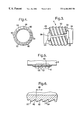
- FIG. 4 is an end view of the scraper element of FIG. 3;
- FIG. 5 is a partial longitudinal cross-section view of the scraper element of FIG. 3;
- FIG. 6 is a large scale cross-section view of portion X identified in FIG. 5;
- FIG. 7 is a cross-section view of the scraper assembly of FIG. 2 in a downhole location in combination with an inflatable packer;
- FIG. 8 is a longitudinal cross-section view of a second scraper assembly according to the present invention.
- a first embodiment of the present invention is shown in FIG. 2.
- a scraper assembly 2 is shown as having a mandrel 4 , a scraper element 6 , a retaining sleeve 8 and a retaining end cap 10 .
- the mandrel 4 is generally cylindrical in shape and has a longitudinal bore 12 extending therethrough.
- the bore 12 is provided with internal screw threads 16 for engagement with downhole equipment such as an inflatable packer or whipstock assembly.
- the diameter of the bore 12 is reduced by means of an internal shoulder 18 which provides an abutment surface for locating against any equipment engaged with the internal screw threads 16 .
- An arrangement is thereby provided which allows the scraper assembly 2 to be conveniently and rigidly incorporated into a string.
- the outer diameter of the mandrel 4 in the region of the uphole end 14 of the scraper assembly 2 is reduced by a first external shoulder 20 and further reduced by a second external shoulder 22 .
- the second external shoulder 22 provides an abutment surface for assisting in locating the retaining sleeve 8 in the correct axial position.
- the retaining sleeve 8 and the first external shoulder 20 define a recess 24 for receiving a circumferential weld 26 . This weld 26 rigidly fixes the retaining sleeve 8 to the mandrel 4 .
- the axial location of the first and second external shoulders 20 , 22 is such that, when the retaining sleeve 8 has been welded in position, two diametrically opposed countersunk bores 28 , 30 may be laterally drilled through the retaining sleeve 8 and the mandrel 4 so as to open on the region of the mandrel bore 12 provided with the internal screw threads 16 .
- Each countersunk bore 28 , 30 is tapped. In this way, setting screws (not shown) may be received within the countersunk bores 28 , 30 so as to abut downhole equipment engaged with the internal screw threads 16 . Rotation of said downhole equipment relative to the scraper assembly 2 is thereby prevented.
- the outer diameter of the mandrel 4 is reduced still further by a third external shoulder 32 located downhole of the counter bores 28 , 30 but uphole of the downhole end of the retaining sleeve 8 .
- the retaining sleeve 8 is a cylinder having a wall of uniform thickness. Consequently, the portion of the retaining sleeve 8 located downhole of the third external shoulder 32 is radially spaced from the mandrel 4 .
- the space 34 receives an uphole end 36 of the scraper element 6 .
- the outer diameter of the mandrel 4 is again reduced by means of a fourth external shoulder 40 .
- the fourth external shoulder 40 provides a surface against which the retaining end cap 10 abuts when in the correct axial position. This position is maintained by means of a weld 42 between the end cap 10 and the mandrel 4 .
- An uphole portion 44 of the end cap 10 defines a cylindrical member having the same wall thickness and outer diameter as that of the retaining sleeve 8 . As a result, said end portion 44 is radially spaced from the mandrel 4 and thereby provides a space 46 for receiving a downhole end 48 of the scraper element 6 .
- FIG. 3 A side view of the scraper element 6 is shown in FIG. 3 .
- the scraper element 6 is generally cylindrical in shape, having an inner diameter greater than the outer diameter of the portion of the mandrel 4 located between the third external shoulder 32 and the fourth external shoulder 40 .
- the outer surface of the scraper element 6 is provided with a set of helical scraper blades or teeth 50 .
- the precise configuration of these teeth 50 will be described below in greater detail with reference to FIGS. 5 and 6.
- FIG. 4 A view of the downhole end 48 of the scraper element 6 is shown in FIG. 4 wherein a number of different types of slot are clearly illustrated. Firstly, a single full depth/full length slot 52 is provided.
- This slot 52 is in the form of a helical cut which completely penetrates the wall thickness of the scraper element 6 and extends the entire length of the element 6 , cutting across the blades or teeth 50 .
- a radial compression force applied to the scraper element 6 will resiliently deform the element 6 and effectively reduce the outer diameter of the element 6 .
- the scraper element 6 has a lobed shape cross-section rather than a circular cross-section when in a relaxed and undeformed state. It is only when the scraper element 6 is deformed in use so as to partially close (or, depending on the geometry, fully close) the slot 52 that the scraper element 6 forms a cylinder with a generally circular cross-section. In this way, the scraper element 6 conforms to the inner dimensions of the wellbore casing and full circumferential engagement of the teeth 50 with the casing is ensured.
- the scraper element 6 is provided with two “H” shaped slots 54 .
- the two “H” shaped slots 54 are circumferentially offset relative to one another by 120°. Each of these slots 54 penetrates the full wall thickness of the scraper element 6 .
- the cross bar portion 56 of the “H” shape profile extends helically through the region between the uphole and downhole ends 36 , 48 of the scraper element 6 .
- a circumferential portion 58 extends in both circumferential directions to sweep an angle of approximately 60°.
- the “H” shaped slots 54 function to provide a leaf spring effect when the scraper element 6 is radially deformed in use. The flexibility and resilience of the scraper element 6 is thereby improved.
- the scraper element 6 is also provided with three partial depth/full length slots 60 . These slots 60 are equispaced about the circumference of the scraper element 6 and are each in the form of a helical groove merely penetrating an outer portion of the wall thickness of the element 6 . Each of these slots 60 extends the full length of the scraper element 6 .
- the purpose of the three partial depth/full length slots 60 is to provide fluid ways for wellbore fluid to flow along during use.
- the helical form of all the slots 52 , 54 , 60 is such that the full circumference of the wellbore is scraped by the teeth 50 with mere longitudinal movement of the scraper assembly 2 without the need for rotation.
- the process of manufacturing the scraper element 6 ideally includes the step of turning the scraper element 6 whilst holding the element 6 in a deformed state wherein the full depth/full length slot 52 is sufficiently closed to reduce the outer diameter of the portion of the scraper element 6 provided with the scraper teeth 50 by 0.176 inches. This process ensures a circular profile of the scraper blades 50 when the scraper assembly 2 is downhole in scraping engagement with a wellbore.
- the region of the scraper element 6 located between the uphole and downhole ends 36 , 48 is provided with four scraper teeth 50 which are each arranged helically about the longitudinal axis of the scraper element 6 .
- the helical arrangement of the teeth 50 assists in allowing wellbore fluid to flow past the scraper assembly 2 when in use.
- a longitudinal cross-section view of the teeth 50 is shown in FIG. 5 and a large scale view of the portion X circled in this figure is shown in FIG. 6 .
- Both FIGS. 5 and 6 show the teeth 50 as having a trailing surface 62 arranged-at an angle 64 to the scraper element 6 longitudinal axis of 25°.
- the scraper assembly 2 When in use, the scraper assembly 2 may be threadedly connected to the downhole end of equipment such as an inflatable packer 70 by means of the internal threads 16 .
- the scraper assembly 2 is shown located downhole in combination with an inflatable packer in FIG. 7 .
- the scraper element 6 In its relaxed state, the scraper element 6 has an outer diameter defined by the teeth 50 which is greater than the inner diameter of the wellbore casing 72 .
- the scraper assembly 2 and inflatable packer 70 are run downhole, the scraper element 6 is radially deformed by the casing 72 . Deformation without undesirable buckling is ensured by means of the slots 52 , 54 , 60 provided in the scraper element 6 .
- the scraper element 6 deforms elastically so that the scraper teeth 50 apply radial force on the inner surface 74 of the casing 72 . Also, the radial deformation is such that the lobed cross-section of the relaxed scraper element 6 becomes circular. The maximum diameter of the scraper element 6 (i.e. the diameter defined by the scraper teeth 50 ) thereby becomes equal to the inner diameter of the casing 72 . Thus, the scraper teeth 50 engage the full circumference of the casing inner surface 74 . Consequently, the entire inner surface 74 of the casing 72 is scraped clean as the scraper assembly 2 is moved down the wellbore.
- the scraper assembly 2 Since the discontinuities in the teeth 50 resulting from the slots 52 , 54 , 60 have a helical form, it is not necessary to rotate the scraper assembly 2 to ensure full circumferential scraping. Furthermore, since the scraper assembly 2 is relatively inexpensive to manufacture, the assembly 2 may be discarded once withdrawn from the wellbore or left in the wellbore as part of an inflatable packer or whipstock assembly.
- FIG. 8 A second embodiment of the present invention is shown in FIG. 8 .
- the components of the scraper assembly 2 ′ shown in this figure differ from the scraper assembly 2 shown in FIG. 2 only in respect of the mandrel 4 ′ and the retaining end cap 10 ′.
- the mandrel 4 ′ has an extended uphole portion with conventional female connecting means 80 .
- the end cap 10 ′ has an extended downhole portion with conventional male connecting means 82 .
- These connecting means 80 , 82 may be employed to integrate the scraper assembly 2 ′ into a string for independent use without an inflatable packer.
- the retaining end cap 10 ′ is fixed to the mandrel 4 ′ by means of a screw connection 84 .
- connection 84 is locked by means of a locking screw 86 extending radially through the end cap 10 ′ so as to abut the mandrel 4 ′.
- This arrangement is in contrast to the fixing arrangement (i.e. the weld 42 ) provided in the scraper assembly 2 shown in FIG. 2 .
Landscapes
- Geology (AREA)
- Life Sciences & Earth Sciences (AREA)
- Engineering & Computer Science (AREA)
- Mining & Mineral Resources (AREA)
- Environmental & Geological Engineering (AREA)
- Fluid Mechanics (AREA)
- Physics & Mathematics (AREA)
- General Life Sciences & Earth Sciences (AREA)
- Geochemistry & Mineralogy (AREA)
- Earth Drilling (AREA)
- Processing And Handling Of Plastics And Other Materials For Molding In General (AREA)
- Electrical Discharge Machining, Electrochemical Machining, And Combined Machining (AREA)
- Dental Tools And Instruments Or Auxiliary Dental Instruments (AREA)
Abstract
Description
Claims (10)
Applications Claiming Priority (3)
| Application Number | Priority Date | Filing Date | Title |
|---|---|---|---|
| GB9816889A GB2340150B (en) | 1998-08-03 | 1998-08-03 | Downhole scraper assembly |
| GB9816889 | 1998-08-03 | ||
| PCT/GB1999/002352 WO2000008300A1 (en) | 1998-08-03 | 1999-07-20 | Downhole scraper assembly |
Publications (1)
| Publication Number | Publication Date |
|---|---|
| US6484802B1 true US6484802B1 (en) | 2002-11-26 |
Family
ID=10836635
Family Applications (1)
| Application Number | Title | Priority Date | Filing Date |
|---|---|---|---|
| US09/762,252 Expired - Lifetime US6484802B1 (en) | 1998-08-03 | 1999-07-20 | Downhole scraper assembly |
Country Status (6)
| Country | Link |
|---|---|
| US (1) | US6484802B1 (en) |
| EP (1) | EP1102914B1 (en) |
| CA (1) | CA2339592C (en) |
| GB (1) | GB2340150B (en) |
| NO (1) | NO319129B1 (en) |
| WO (1) | WO2000008300A1 (en) |
Cited By (13)
| Publication number | Priority date | Publication date | Assignee | Title |
|---|---|---|---|---|
| GB2399365A (en) * | 2003-03-10 | 2004-09-15 | Weatherford Lamb | Packer with integral cleaning device |
| US20060124359A1 (en) * | 2004-12-10 | 2006-06-15 | Bunney Larry R | Method of avoiding the need for a scraper run in drill out operations and a downhole drilling motor assembly |
| US20080145139A1 (en) * | 2004-08-24 | 2008-06-19 | Specialised Petroleum Services Group Limited | Clamp |
| US20100258318A1 (en) * | 2007-10-03 | 2010-10-14 | M-I Llc | Downhole scraper |
| CN104632131A (en) * | 2014-12-31 | 2015-05-20 | 大港油田集团有限责任公司 | Oil scraping device for sucker rod |
| US9435176B2 (en) | 2012-10-26 | 2016-09-06 | Weatherford Technology Holdings, Llc | Deburring mill tool for wellbore cleaning |
| US9458699B2 (en) | 2013-10-30 | 2016-10-04 | Ge Oil & Gas Pressure Control Lp | Slotted wellhead and multibowl polishing tool with woven polishing belt |
| US9816355B2 (en) | 2014-07-24 | 2017-11-14 | Baker Hughes, A Ge Company, Llc | Multi-purpose through tubing tool |
| US10214997B2 (en) * | 2013-06-27 | 2019-02-26 | Welltec A/S | Downhole cleaning tool and cleaning method |
| CN110410037A (en) * | 2019-08-27 | 2019-11-05 | 阜宁县石油机械有限公司 | A casing scraper |
| CN110984915A (en) * | 2019-12-19 | 2020-04-10 | 牡丹江天庆石油机械设备有限公司 | Elastic paraffin scraping and sand washing type guide cone for oil field |
| CN111550214A (en) * | 2020-06-10 | 2020-08-18 | 中国石油天然气股份有限公司 | Clear stifled device of injection well water injection mandrel centre bore |
| CN120867682A (en) * | 2025-09-29 | 2025-10-31 | 中国石油集团西部钻探工程有限公司 | Magnetic sleeve scraping device |
Families Citing this family (1)
| Publication number | Priority date | Publication date | Assignee | Title |
|---|---|---|---|---|
| CN113323630B (en) * | 2020-02-28 | 2023-01-31 | 中国石油化工股份有限公司 | A variable-diameter casing scraper |
Citations (12)
| Publication number | Priority date | Publication date | Assignee | Title |
|---|---|---|---|---|
| US1899269A (en) | 1932-05-23 | 1933-02-28 | Hakes Carlton Jones | Tool for cleaning tubes |
| US2735123A (en) | 1956-02-21 | Pipe cleaning tool | ||
| US3011556A (en) | 1957-09-20 | 1961-12-05 | David M Best | Casing scraper |
| US4050514A (en) | 1976-09-01 | 1977-09-27 | The Steel Company Of Canada, Limited | Paraffin sucker rod scraper and rod centralizer |
| US4558738A (en) * | 1984-04-02 | 1985-12-17 | Howard Sr Robert G | Oil well casing scraper |
| US4572291A (en) | 1984-11-06 | 1986-02-25 | Robison Robert E | Well casing scraper |
| US4648447A (en) | 1985-09-11 | 1987-03-10 | Bowen Tools, Inc. | Casing scraper |
| US4798246A (en) * | 1987-04-22 | 1989-01-17 | Best David M | Pipe scraper |
| US5452760A (en) | 1994-09-19 | 1995-09-26 | Enterra Patco Oilfield Products Limited | Well pump tubing scrapers |
| US6152221A (en) * | 1999-02-08 | 2000-11-28 | Specialised Petroleum Services Limited | Apparatus with retractable cleaning members |
| US6182754B1 (en) * | 1997-11-19 | 2001-02-06 | Rg Industries Ltd. | Helical scraper apparatus for a reciprocating sucker rod |
| US6209647B1 (en) * | 1997-02-21 | 2001-04-03 | Billy L. Brown, Jr. | Down hole casing string cleaning device and method |
Family Cites Families (1)
| Publication number | Priority date | Publication date | Assignee | Title |
|---|---|---|---|---|
| FR383660A (en) * | 1907-11-07 | 1908-03-14 | Emil Nilsson | Scraper for cleaning tubes |
-
1998
- 1998-08-03 GB GB9816889A patent/GB2340150B/en not_active Expired - Fee Related
-
1999
- 1999-07-20 WO PCT/GB1999/002352 patent/WO2000008300A1/en not_active Ceased
- 1999-07-20 CA CA002339592A patent/CA2339592C/en not_active Expired - Fee Related
- 1999-07-20 US US09/762,252 patent/US6484802B1/en not_active Expired - Lifetime
- 1999-07-20 EP EP99934905A patent/EP1102914B1/en not_active Expired - Lifetime
-
2001
- 2001-02-02 NO NO20010577A patent/NO319129B1/en not_active IP Right Cessation
Patent Citations (12)
| Publication number | Priority date | Publication date | Assignee | Title |
|---|---|---|---|---|
| US2735123A (en) | 1956-02-21 | Pipe cleaning tool | ||
| US1899269A (en) | 1932-05-23 | 1933-02-28 | Hakes Carlton Jones | Tool for cleaning tubes |
| US3011556A (en) | 1957-09-20 | 1961-12-05 | David M Best | Casing scraper |
| US4050514A (en) | 1976-09-01 | 1977-09-27 | The Steel Company Of Canada, Limited | Paraffin sucker rod scraper and rod centralizer |
| US4558738A (en) * | 1984-04-02 | 1985-12-17 | Howard Sr Robert G | Oil well casing scraper |
| US4572291A (en) | 1984-11-06 | 1986-02-25 | Robison Robert E | Well casing scraper |
| US4648447A (en) | 1985-09-11 | 1987-03-10 | Bowen Tools, Inc. | Casing scraper |
| US4798246A (en) * | 1987-04-22 | 1989-01-17 | Best David M | Pipe scraper |
| US5452760A (en) | 1994-09-19 | 1995-09-26 | Enterra Patco Oilfield Products Limited | Well pump tubing scrapers |
| US6209647B1 (en) * | 1997-02-21 | 2001-04-03 | Billy L. Brown, Jr. | Down hole casing string cleaning device and method |
| US6182754B1 (en) * | 1997-11-19 | 2001-02-06 | Rg Industries Ltd. | Helical scraper apparatus for a reciprocating sucker rod |
| US6152221A (en) * | 1999-02-08 | 2000-11-28 | Specialised Petroleum Services Limited | Apparatus with retractable cleaning members |
Cited By (22)
| Publication number | Priority date | Publication date | Assignee | Title |
|---|---|---|---|---|
| US20040177967A1 (en) * | 2003-03-10 | 2004-09-16 | Hirth David E. | Packer with integral cleaning device |
| US7048055B2 (en) | 2003-03-10 | 2006-05-23 | Weatherford/Lamb, Inc. | Packer with integral cleaning device |
| GB2399365B (en) * | 2003-03-10 | 2006-06-14 | Weatherford Lamb | Packer with integral cleaning device |
| GB2399365A (en) * | 2003-03-10 | 2004-09-15 | Weatherford Lamb | Packer with integral cleaning device |
| US8388256B2 (en) | 2004-08-24 | 2013-03-05 | Specialised Petroleum Services Group Limited | Clamp |
| US9410570B2 (en) | 2004-08-24 | 2016-08-09 | Specialised Petroleum Services Group Limited | Clamp |
| US20080145139A1 (en) * | 2004-08-24 | 2008-06-19 | Specialised Petroleum Services Group Limited | Clamp |
| US7520340B2 (en) | 2004-12-10 | 2009-04-21 | Bunney Larry R | Method of avoiding the need for a scraper run in drill out operations and a downhole drilling motor assembly |
| US20060124359A1 (en) * | 2004-12-10 | 2006-06-15 | Bunney Larry R | Method of avoiding the need for a scraper run in drill out operations and a downhole drilling motor assembly |
| US20100258318A1 (en) * | 2007-10-03 | 2010-10-14 | M-I Llc | Downhole scraper |
| US8826986B2 (en) | 2007-10-03 | 2014-09-09 | M-I L.L.C. | Downhole scraper |
| US9435176B2 (en) | 2012-10-26 | 2016-09-06 | Weatherford Technology Holdings, Llc | Deburring mill tool for wellbore cleaning |
| US10214997B2 (en) * | 2013-06-27 | 2019-02-26 | Welltec A/S | Downhole cleaning tool and cleaning method |
| US9458699B2 (en) | 2013-10-30 | 2016-10-04 | Ge Oil & Gas Pressure Control Lp | Slotted wellhead and multibowl polishing tool with woven polishing belt |
| US9816355B2 (en) | 2014-07-24 | 2017-11-14 | Baker Hughes, A Ge Company, Llc | Multi-purpose through tubing tool |
| CN104632131A (en) * | 2014-12-31 | 2015-05-20 | 大港油田集团有限责任公司 | Oil scraping device for sucker rod |
| CN104632131B (en) * | 2014-12-31 | 2018-06-15 | 大港油田集团有限责任公司 | A kind of oil-scraping device for sucker rod |
| CN110410037A (en) * | 2019-08-27 | 2019-11-05 | 阜宁县石油机械有限公司 | A casing scraper |
| CN110984915A (en) * | 2019-12-19 | 2020-04-10 | 牡丹江天庆石油机械设备有限公司 | Elastic paraffin scraping and sand washing type guide cone for oil field |
| CN111550214A (en) * | 2020-06-10 | 2020-08-18 | 中国石油天然气股份有限公司 | Clear stifled device of injection well water injection mandrel centre bore |
| CN120867682A (en) * | 2025-09-29 | 2025-10-31 | 中国石油集团西部钻探工程有限公司 | Magnetic sleeve scraping device |
| CN120867682B (en) * | 2025-09-29 | 2026-01-20 | 中国石油集团西部钻探工程有限公司 | Magnetic sleeve scraping device |
Also Published As
| Publication number | Publication date |
|---|---|
| CA2339592A1 (en) | 2000-02-17 |
| GB2340150B (en) | 2002-09-18 |
| EP1102914B1 (en) | 2004-07-07 |
| NO319129B1 (en) | 2005-06-20 |
| CA2339592C (en) | 2006-01-03 |
| NO20010577L (en) | 2001-04-02 |
| NO20010577D0 (en) | 2001-02-02 |
| EP1102914A1 (en) | 2001-05-30 |
| WO2000008300A1 (en) | 2000-02-17 |
| GB9816889D0 (en) | 1998-09-30 |
| GB2340150A (en) | 2000-02-16 |
Similar Documents
| Publication | Publication Date | Title |
|---|---|---|
| US6484802B1 (en) | Downhole scraper assembly | |
| US6981547B2 (en) | Wire lock expandable connection | |
| CA2091547C (en) | Centralizer | |
| EP3372779B1 (en) | Mproved downhole scraping and/or brushing tool | |
| EP2872725B1 (en) | Device arranged for attaching a mandrel on a tubular body | |
| DE69530666T9 (en) | Protective shield for an antenna, wear band and stabilizer for a tool for measuring while drilling | |
| US20200109607A1 (en) | Slimline stop collar | |
| US6546581B1 (en) | Casing scraper | |
| EP1838947B1 (en) | Centraliser | |
| EP3879066A1 (en) | Slimline stop collar with solid cam ring | |
| US11136833B2 (en) | Float equipment for a wellbore | |
| US9752393B2 (en) | Tool assembly apparatus and method | |
| US20040060699A1 (en) | Torque reducing tubing component | |
| CA2764311A1 (en) | No-go tag systems and methods for progressive cavity pumps | |
| AU2021106799A4 (en) | Drill rods having stabilizers and systems and methods comprising same | |
| GB2184761A (en) | Drilling directional boreholes | |
| EP1308624B1 (en) | Submersible motor-driven pump | |
| EP4031785B1 (en) | Slide ring seal assembly which can be axially mounted | |
| US20110186287A1 (en) | Cleaning Device | |
| US20240229562A1 (en) | Cutter assembly | |
| CN104471181B (en) | It is arranged to device tube rod being attached on tubular body | |
| US20220213741A1 (en) | Mechanical locking system to eliminate movement between downhole components | |
| CA3180596A1 (en) | Drill rods having stabilizers, and systems and methods comprising same |
Legal Events
| Date | Code | Title | Description |
|---|---|---|---|
| AS | Assignment |
Owner name: SMITH INTERNATIONAL, INC., TEXAS Free format text: ASSIGNMENT OF ASSIGNORS INTEREST;ASSIGNORS:MCGARIAN, BRUCE;GILLIES, IAN;REEL/FRAME:013228/0178 Effective date: 20010302 |
|
| STCF | Information on status: patent grant |
Free format text: PATENTED CASE |
|
| FPAY | Fee payment |
Year of fee payment: 4 |
|
| FPAY | Fee payment |
Year of fee payment: 8 |
|
| FPAY | Fee payment |
Year of fee payment: 12 |
|
| AS | Assignment |
Owner name: WELLBORE INTEGRITY SOLUTIONS LLC, TEXAS Free format text: ASSIGNMENT OF ASSIGNORS INTEREST;ASSIGNOR:SMITH INTERNATIONAL, INC.;REEL/FRAME:051470/0680 Effective date: 20191231 |
|
| AS | Assignment |
Owner name: WELLS FARGO BANK, NATIONAL ASSOCIATION, AS COLLATERAL AGENT, NORTH CAROLINA Free format text: ABL PATENT SECURITY AGREEMENT;ASSIGNOR:WELLBORE INTEGRITY SOLUTIONS LLC;REEL/FRAME:052184/0900 Effective date: 20191231 |
|
| AS | Assignment |
Owner name: WELLBORE INTEGRITY SOLUTIONS LLC, TEXAS Free format text: RELEASE BY SECURED PARTY;ASSIGNOR:WELLS FARGO BANK, NATIONAL ASSOCIATION;REEL/FRAME:056910/0165 Effective date: 20210715 |