US6454304B1 - Apparatus for sensing and restraining an occupant of a vehicle seat - Google Patents
Apparatus for sensing and restraining an occupant of a vehicle seat Download PDFInfo
- Publication number
- US6454304B1 US6454304B1 US09/425,851 US42585199A US6454304B1 US 6454304 B1 US6454304 B1 US 6454304B1 US 42585199 A US42585199 A US 42585199A US 6454304 B1 US6454304 B1 US 6454304B1
- Authority
- US
- United States
- Prior art keywords
- buckle
- seat belt
- tension
- anchor
- weight
- Prior art date
- Legal status (The legal status is an assumption and is not a legal conclusion. Google has not performed a legal analysis and makes no representation as to the accuracy of the status listed.)
- Expired - Lifetime
Links
Images


Classifications
-
- B—PERFORMING OPERATIONS; TRANSPORTING
- B60—VEHICLES IN GENERAL
- B60R—VEHICLES, VEHICLE FITTINGS, OR VEHICLE PARTS, NOT OTHERWISE PROVIDED FOR
- B60R22/00—Safety belts or body harnesses in vehicles
- B60R22/48—Control systems, alarms, or interlock systems, for the correct application of the belt or harness
-
- B—PERFORMING OPERATIONS; TRANSPORTING
- B60—VEHICLES IN GENERAL
- B60R—VEHICLES, VEHICLE FITTINGS, OR VEHICLE PARTS, NOT OTHERWISE PROVIDED FOR
- B60R22/00—Safety belts or body harnesses in vehicles
- B60R22/18—Anchoring devices
-
- B—PERFORMING OPERATIONS; TRANSPORTING
- B60—VEHICLES IN GENERAL
- B60R—VEHICLES, VEHICLE FITTINGS, OR VEHICLE PARTS, NOT OTHERWISE PROVIDED FOR
- B60R22/00—Safety belts or body harnesses in vehicles
- B60R22/18—Anchoring devices
- B60R2022/1806—Anchoring devices for buckles
-
- B—PERFORMING OPERATIONS; TRANSPORTING
- B60—VEHICLES IN GENERAL
- B60R—VEHICLES, VEHICLE FITTINGS, OR VEHICLE PARTS, NOT OTHERWISE PROVIDED FOR
- B60R22/00—Safety belts or body harnesses in vehicles
- B60R22/48—Control systems, alarms, or interlock systems, for the correct application of the belt or harness
- B60R2022/4808—Sensing means arrangements therefor
- B60R2022/4841—Sensing means arrangements therefor for sensing belt tension
-
- B—PERFORMING OPERATIONS; TRANSPORTING
- B60—VEHICLES IN GENERAL
- B60R—VEHICLES, VEHICLE FITTINGS, OR VEHICLE PARTS, NOT OTHERWISE PROVIDED FOR
- B60R22/00—Safety belts or body harnesses in vehicles
- B60R22/48—Control systems, alarms, or interlock systems, for the correct application of the belt or harness
- B60R2022/4808—Sensing means arrangements therefor
- B60R2022/4858—Sensing means arrangements therefor for sensing pressure on seat
Definitions
- the present invention relates to an apparatus for sensing the weight of an object in a vehicle seat and for controlling a restraint system in accordance with the weight of the object.
- An apparatus for restraining an occupant of a vehicle seat typically includes seat belt webbing, a tongue on the webbing, and a seat belt buckle.
- An occupant weight sensor is mounted in the vehicle seat. The weight sensor provides an output signal which indicates a sensed weight of the occupant of the seat.
- the apparatus further includes an inflatable vehicle occupant protection device, such as an air bag, a source of inflation fluid for inflating the inflatable occupant protection device, and a controller.
- the source of inflation fluid is actuated by the controller and directs inflation fluid into the inflatable occupant protection device.
- the controller receives the output signal from the weight sensor in the seat and controls the amount of inflation fluid directed into the inflatable occupant protection device in response to the output signal from the weight sensor. If the weight sensed by the weight sensor is below a predetermined amount, i.e., a low weight in the seat or no occupant in the seat, then the controller disables the source of inflation fluid to prevent inflation of the inflatable occupant protection device.
- the controller thus controls the fluid pressure in the inflatable protection device and the restraining force provided by the inflatable protection device based on the sensed weight of the occupant.
- the controller may also disable the inflatable protection device.
- an apparatus includes seat belt webbing for restraining an object, such as a vehicle occupant, in a vehicle seat.
- a sensor associated with the vehicle seat senses a sensed weight of the object in the vehicle seat. The sensed weight may differ from the actual weight of the object.
- a seat belt tension sensor senses the tension in the seat belt webbing.
- a controller determines a computed weight of the object as a function of both the sensed weight and the tension in the seat belt webbing.
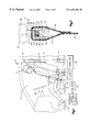
- FIG. 1 is a schematic view of a restraint system in accordance with the present invention
- FIG. 2 is a schematic sectional view of a seat belt buckle and anchor of the restraint system of FIG. 1 showing a first embodiment of a seat belt tension sensor;
- FIG. 3 is a view taken along the line 3 — 3 of FIG. 2;
- FIG. 4 is a schematic sectional view of a second embodiment of a seat belt tension sensor
- FIG. 5 is a schematic sectional view of a third embodiment of a seat belt tension sensor
- FIG. 6 is a schematic sectional view of a fourth embodiment of a seat belt tension sensor
- FIG. 7 is a schematic sectional view of a fifth embodiment of a seat belt tension sensor.
- FIG. 8 is a schematic sectional view of a sixth embodiment of a seat belt tension sensor.
- a restraint system 10 (FIG. 1) includes seat belt webbing 12 for restraining an object, such as a vehicle occupant 14 , in a vehicle seat 16 . It is to be understood that the present invention could be used in an occupant restraint system for restraining an occupant or object, such as a child safety seat, in a passenger seat.
- a length of the seat belt webbing 12 is extensible about the vehicle occupant 14 .
- One end of the seat belt 12 is anchored to the vehicle body 18 at an anchor point 20 located on one side of the seat 16 .
- the opposite end of the seat belt 12 is attached to a retractor 22 which is usually secured to the vehicle body 18 on the same side of the seat 16 as the anchor point 20 .
- the seat belt 12 passes through a tongue assembly 24 and a D-ring 26 that is located above the retractor 22 and the anchor point 20 .
- the seat belt is wound on the retractor 22 , as known in the art.
- the tongue assembly 24 is connected with a buckle 30 .
- the buckle 30 is connected to the vehicle body 18 by an anchor 32 .
- An inflatable vehicle occupant protection device such as an air bag (not shown), is stored in a folded condition in a portion of the vehicle, such as a steering wheel 40 or in a dashboard of the vehicle.
- an inflator 42 is actuated and provides inflation fluid for inflating the inflatable occupant protection device.
- the inflation fluid may be generated by combustion of pyrotechnic material or simply released from a pressurized container, as known in the art.
- the inflation fluid directed into the air bag inflates the air bag from the folded condition to an inflated condition in which the air bag extends into an occupant compartment 43 .
- the air bag then helps protect the occupant 14 from a forceful impact with parts of the vehicle.
- An electronic controller 44 such as a microcomputer, is operatively connected to a vehicle crash sensor (not shown).
- the crash sensor may be any of several known types.
- the amount of inflation fluid directed into the air bag is controlled so that the air bag provides a restraining force that is related to the weight of the occupant 14 of the seat 16 .
- a sensor 50 is mounted on the seat 16 . The sensor 50 senses a sensed weight of the occupant 14 of the vehicle seat 16 . The sensed weight may differ from the actual weight of the occupant 14 .
- the occupant 14 During operation of the vehicle, the occupant 14 usually has the tongue 24 connected with the buckle 30 .
- the retractor 22 produces a tension on the seat belt webbing 12 which acts on the occupant 14 .
- the tension in the seat belt webbing 12 pulls down on the occupant 14 causing the sensor 50 to be subjected to the weight of the occupant 14 along with the downward force resulting from the tension in the seat belt 12 .
- the output signal from the sensor 50 thus indicates a sensed weight of the occupant 14 which may be greater than the actual weight of the occupant.
- a seat belt tension sensor 60 senses the tension in the seat belt webbing 12 and provides an output signal indicating the tension in the seat belt.
- the output signals from the sensor 50 and the tension sensor 60 are received by the controller 44 .
- the controller 44 determines a computed weight of the occupant 14 as a function of both the sensed weight and the tension in the seat belt 12 .
- the sensed weight differs from the actual weight of the occupant 14 by a first amount.
- the computed weight differs from the actual weight of the occupant 14 by a second amount that is less than the first amount and may be zero.
- the controller 44 controls the amount of inflation fluid directed to the air bag by the inflator 42 based on the computed weight of the object or occupant in the seat 16 . If the computed weight is below a predetermined value or zero, the controller 44 disables the inflator 42 to prevent inflation fluid from being directed to the air bag. Alternatively, if the computed weight is below the predetermined value, the controller 44 causes the inflator to direct a minimal amount of inflation fluid to the inflatable occupant protection device.
- the controller 44 may have a look-up table that stores a plurality of empirical sensed weight values, a plurality of empirical seat belt tension values, and a plurality of computed weight values corresponding to combinations of the sensed weight values and the seat belt tension values.
- the computed weight values stored in the look-up table could be predetermined empirically and/or through computations based on a predetermined functional relationship between computed weight and the empirical values of sensed weight and seat belt tension.
- the controller 44 would then identify a predetermined computed weight value corresponding to empirical values of sensed weight and seat belt tension.
- the controller 44 could determine the computed weight by performing a computation based on a predetermined functional relationship between computed weight, sensed weight, and belt tension which is derived from empirical data. In either case, the computed weight determined by the controller 44 more closely approximates the actual weight of the occupant 14 , as compared with the sensed weight indicated by the sensor 50 because the effect of the tension in the seat belt 12 is considered in determining the computed weight.
- the sensor 50 may also sense the size and shape of the object in the seat to determine if a child safety seat is located in the passenger seat. If a child safety seat is located in the passenger seat, the tongue is connected with the buckle to secure the child safety seat to the passenger seat. Typically, the seat belt webbing is pulled as tight as possible to secure the child safety seat to the passenger seat. The tension in the seat belt webbing pulls down on the child safety seat causing the sensor 50 to be subjected to the weight of the child safety seat with the child therein and the downward force resulting from the tension in the seat belt. The output signal from the sensor 50 thus indicates a sensed weight of the child safety seat and the child therein which is greater than the actual weight of the child safety seat and the child.
- the seat belt tension sensor 60 senses the tension in the seat belt webbing.
- the controller 44 determines a computed weight of the child safety seat and the child therein. If the sensor 50 senses that a child safety seat is located in the passenger seat, the controller 44 disables the source of inflation fluid to prevent inflation of the inflatable occupant protection device. Alternatively, if the sensor 50 senses that a child safety seat is located in the passenger seat, the controller 44 causes the source of inflation fluid to direct a minimal amount of inflation fluid to the inflatable occupant protection device.
- FIGS. 2 and 3 A first embodiment of a seat belt tension sensor 60 for use in the occupant restraint system 10 is shown in FIGS. 2 and 3.
- the buckle 30 includes a U-shaped extension 70 (FIG. 3) extending from a buckle frame 72 (FIG. 2 ).
- the U-shaped extension 70 includes a pair of parallel arms 74 and 75 (FIG. 3) extending from the buckle frame 72 .
- a cross piece 76 extends between the arms 74 and 75 and perpendicular to the arms.
- the buckle frame 72 and the U-shape extension 70 define an opening 78 .
- the anchor 32 (FIG. 2) includes webbing 82 extending through the opening 78 .
- the webbing 82 is attached to itself to define a loop 84 .
- the loop 84 extends around a U-shaped floating member 90 to connect the anchor 32 with the floating member. Accordingly, the floating member 90 is fixed relative to the anchor 32 and the vehicle body 18 .
- the floating member 90 includes a pair of parallel arms 92 (FIG. 2 ).
- a cross piece 94 extends between the arms 92 and perpendicular to the arms.
- the cross piece 94 has a lower surface 95 that extends parallel to an upper surface 96 of the cross piece 76 of the extension 70 .
- the arms 92 of the floating member 90 engage the cross piece 76 of the extension 70 to guide movement of the extension and the buckle 30 relative to the floating member 90 and the anchor 32 .
- Springs 97 extend between the surface 96 of the cross piece 76 and the surface 95 of the cross piece 94 .
- the springs 97 allow the buckle 30 to move upward, as viewed in FIGS. 2 and 3, relative to the floating member 90 and the anchor 32 .
- the springs 97 bias the buckle 30 in a downward direction relative to the anchor 32 and the floating member 90 to an initial position, as shown in FIGS. 2 and 3. Movement of the buckle 30 relative to the floating member 90 and the anchor 32 results from a force proportional to the tension in the seat belt 12 .
- Electrical contacts 98 are connected to the cross piece 94 of the floating member 90 adjacent to the arms 74 and 75 .
- Electrical contacts 100 are connected to the arms 74 and 75 of the extension 70 .
- the electrical contacts 98 and 100 act as a switch in a first electrical circuit (not shown). When the contacts 98 and 100 are spaced apart, the switch is open. When the contacts 98 and 100 engage, the switch is closed and the first electrical circuit is completed.
- the electrical contacts 100 are spaced from the contacts 98 a first distance, shown in FIG. 3, when the buckle 30 is in the initial position.
- the electrical contacts 100 engage the electrical contacts 98 when the buckle 30 moves through the first distance upward relative to the anchor 32 .
- the first electrical circuit is completed to send a first signal to the controller that a first predetermined amount of tension is being applied to the seat belt 12 .
- Electrical contacts 102 are connected to the arms 74 and 75 at a location spaced below the electrical contacts 100 , as viewed in FIG. 3 .
- the electrical contacts 98 and 102 act as a switch in a second electrical circuit (not shown). When the contacts 98 and 100 are spaced apart, the switch is open. When the contacts 98 and 102 engage, the switch is closed and the second electrical circuit is completed.
- the electrical contacts 102 are spaced from the contacts 98 a second distance greater than the first distance when the buckle 30 is in the initial position.
- the electrical contacts 102 engage the electrical contacts 98 when the buckle 30 moves through the second distance relative to the anchor 32 .
- the second electrical circuit is completed to send a second signal to the controller that a second predetermined amount of tension, larger than the first predetermined amount, is being applied to the seat belt 12 .
- the buckle 30 moves upward relative to the floating member 90 a distance equal to or greater than the first distance and less than the second distance.
- the contacts 98 engage the contacts 100 when the buckle 30 has moved relative to the floating member 90 through the first distance.
- the first electrical circuit is completed when the contacts 98 engage the contacts 100 , and a signal indicating that the first predetermined amount of tension is being applied to the seat belt 12 is sent to the controller 44 .
- the buckle 30 moves upward relative to the floating member 90 a distance equal to or greater than the second distance.
- the contacts 98 engage the contacts 102 when the buckle 30 has moved relative to the floating member 90 through the second distance.
- the second electrical circuit is completed when the contacts 98 engage the contacts 102 and a signal indicating that the second predetermined amount of tension is being applied to the seat belt 12 is sent to the controller 44 . Accordingly, a signal is sent to the controller 44 in a step manner.
- FIG. 4 A second embodiment of a seat belt tension sensor for use in the occupant restraint system 10 of FIG. 1 is illustrated in FIG. 4 . Since the embodiment of the seat belt tension sensor illustrated in FIG. 4 is generally similar to the embodiment of the seat belt tension sensor illustrated in FIGS. 2-3, similar numerals will be utilized to designate similar components.
- a leaf spring 110 has end portions 112 and 114 and a curved portion 116 extending between the end portions.
- the end portion 112 is fixedly connected to a cross piece 94 of a floating member 90 .
- the end portion 112 is connected to the cross piece 94 adjacent an arm 74 of extension 70 of the buckle 30 .
- the curved portion 116 engages a surface 96 of a cross piece 76 of the extension 70 .
- the spring 110 biases the buckle 30 downward relative to the floating member 90 and anchor 32 into an initial position, as shown in FIG. 4 .
- An electrical contact 118 is connected to end portion 114 of the spring 110 .
- the spring 110 flattens out and the end portion 114 moves to the right, as viewed in FIG. 4, along the surface 95 of the cross piece 94 .
- An electrical contact 122 is connected to the cross piece 94 of the floating member 90 .
- the contacts 118 and 122 act as a switch in a first electrical circuit (not shown). When the contacts 118 and 122 are spaced apart, the switch is open. When the contacts 118 and 122 engage, the switch is closed and the first electrical circuit is completed.
- the electrical contact 122 is spaced to the right of the contact 118 when the buckle 30 is in the initial position.
- the electrical contact 118 on the spring 110 engages the electrical contact 122 when the buckle 30 moves relative to the anchor 32 through a first distance.
- the first electrical circuit is completed to send a first signal to the controller 44 that a first predetermined amount of tension is being applied to the seat belt 12 .
- An electrical contact 124 is connected to the cross piece 94 spaced to the right of the contact 122 .
- the contacts 118 and 124 act as a switch in a second electrical circuit (not shown). When the contacts 118 and 124 are spaced apart, the switch is open. When the contacts 118 and 124 engage, the switch is closed and the second electrical circuit is completed.
- the electrical contact 118 engages the contact 124 when the buckle 30 moves through a second distance greater than the first distance relative to the anchor 32 .
- the second electrical circuit is completed to send a second signal to the controller 44 that a second predetermined amount of tension is being applied to the seat belt 12 .
- the buckle 30 moves upward relative to the floating member 90 a distance equal to or greater than the first distance and less than the second distance.
- the contact 118 engages the contact 122 when the buckle 30 has moved relative to the floating member 90 through the first distance.
- the first electrical circuit is completed when the contact 118 engages the contact 122 and a signal indicating that the first predetermined amount of tension is being applied to the seat belt 12 is sent to the controller 44 .
- the buckle 30 moves upward relative to the floating member 90 a distance equal to or greater than the second distance.
- the contact 118 engages the contact 124 when the buckle 30 has moved relative to the floating member 90 through the second distance.
- the second electrical circuit is completed when the contact 118 engages the contact 124 , and a signal indicating that the second predetermined amount of tension is being applied to the seat belt 12 is sent to the controller 44 . Accordingly, a signal is sent to the controller 44 in a step manner.
- an inductive sensor could be used instead of the contacts 118 , 122 , and 124 .
- FIG. 5 A third embodiment of a seat belt tension sensor for use in the occupant restraint system 10 of FIG. 1 is illustrated in FIG. 5 . Since the embodiment of the seat belt tension sensor illustrated in FIG. 5 is generally similar to the embodiment of the seat belt tension sensor illustrated in FIGS. 2-3, similar numerals will be utilized to designate similar components.
- a coil spring 130 extends between a surface 95 of a floating member 90 and a surface 96 of an extension 70 of a buckle 30 .
- the spring 130 biases the seat belt buckle 30 downward relative to the floating member 90 and the anchor 32 to an initial position, as shown in FIG. 5 .
- An electrical contact 132 is connected to a cross piece 94 of the floating member 90 adjacent an arm 75 of the extension 70 .
- An electrical contact 134 is connected to the cross piece 94 adjacent an arm 74 of the extension 70 .
- a spring 136 extends from a cross piece 76 of the extension 70 toward the electrical contact 132 on the floating member 90 .
- the spring 136 is weaker than the spring 130 .
- An electrical contact 138 is connected to an end of the spring 136 .
- the contacts 122 and 138 act as a switch in a first electrical circuit (not shown). When the contacts 132 and 138 are spaced apart, the switch is open. When the contacts 132 and 138 engage, the switch is closed and the first electrical circuit is completed.
- the contact 138 is spaced from the contact 132 a first distance when the buckle 30 is in the initial position.
- the electrical contact 138 engages the electrical contact 132 when the buckle 30 moves relative to the anchor 32 through the first distance.
- the first electrical circuit is completed to send a signal to the controller 44 that a first predetermined amount of tension is being applied to the seat belt 12 .
- An electrical contact 140 is connected to a protrusion 142 extending from the cross piece 76 .
- the protrusion 142 extends toward the electrical contact 134 on the floating member 90 .
- the contacts 134 and 140 act as a switch in a second electrical circuit (not shown). When the contacts 134 and 140 are spaced apart, the switch is open. When the contacts 134 and 140 engage, the switch is closed and the second electrical circuit is completed.
- the contact 140 is spaced from the contact 134 a second distance larger than the first distance when the buckle 30 is in the initial position.
- the electrical contact 140 on the protrusion 142 engages the electrical contact 134 when the buckle 30 moves relative to the anchor 32 through the second distance.
- the second electrical circuit is completed to send a signal to the controller 44 that a second predetermined amount of tension is being applied to the seat belt 12 .
- the buckle 30 moves upward relative to the floating member 90 a distance equal to or greater than the first distance and less than the second distance.
- the contact 138 engages the contact 132 when the buckle 30 has moved relative to the floating member 90 through the first distance.
- the first electrical circuit is completed when the contact 138 engages the contact 132 , and a signal indicating that the first predetermined amount of tension is being applied to the seat belt 12 is sent to the controller 44 .
- the buckle 30 moves upward relative to the floating member 90 a distance equal to the second distance.
- the contact 140 engages the contact 134 when the buckle 30 moves relative to the floating member 90 through the second distance.
- the second electrical circuit is completed when the contact 140 engages the contact 134 , and a signal indicating that the second predetermined amount of tension is being applied to the seat belt 12 is sent to the controller 44 . Accordingly, a signal is sent to the controller 44 in a step manner.
- FIG. 6 A fourth embodiment of a seat belt tension sensor for use in the occupant restraint system 10 of FIG. 1 is illustrated in FIG. 6 . Since the embodiment of the seat belt tension sensor illustrated in FIG. 6 is generally similar to the embodiment of the seat belt tension sensor illustrated in FIGS. 2-3, similar numerals will be utilized to designate similar components.
- Springs 146 extend between a surface 96 of an extension 70 of a buckle 30 and a surface 95 of a floating member 90 .
- the springs 146 bias the seat belt buckle 30 in a downward direction relative to the floating member 90 and an anchor 32 into an initial position, as shown in FIG. 6 .
- An end 148 of an electrically conductive arm 150 is pivotally connected to a cross piece 94 of the floating member 90 .
- An opposite end 152 of the arm 150 is located in a slot 154 in a cross piece 76 of the extension 70 .
- the arm 150 is pivotable about the end 152 relative to the cross piece 76 .
- the end 152 slides in the slot 154 as the buckle 30 moves relative to the anchor 32 .
- An electrical contact 158 is located in a middle portion of the slot 154 .
- the end 152 of the arm 150 and the contact 158 act as a switch in a first electrical circuit (not shown). When the end 152 and the contact 158 are spaced apart, the switch is open. When the end 152 and the contact 158 engage, the switch is closed and the first electrical circuit is completed.
- the contact 158 is spaced to the left of the end 152 of the arm 150 when the buckle 30 is in the initial position.
- the end 152 of the arm 150 engages the contact 158 when the buckle 30 moves relative to the anchor 32 through a first distance.
- the first electrical circuit is completed to send a signal to the controller 44 that a first predetermined amount of tension is being applied to the seat belt 12 .
- An electrical contact 160 is located adjacent one end of the slot 154 and to the left of the contact 158 .
- the end 152 of the arm 150 and the contact 160 act as a switch is a second electrical circuit (not shown). When the end 152 and the contact 160 are spaced apart, the switch is open. When the end 152 and the contact 160 engage, the switch is closed and the second electrical circuit is completed.
- the end 152 engages the contact 160 to complete a second electrical circuit when the buckle 30 moves a second distance, greater than the first distance, relative to the anchor 32 .
- the second electrical circuit is completed to send a signal to the controller 44 that a second predetermined amount of tension is being applied to the seat belt 12 .
- the buckle 30 moves upward relative to the floating member 90 a distance equal to or greater than the first distance and less than the second distance.
- the end 152 of the arm 150 engages the contact 158 when the buckle 130 moves relative to the floating member 90 through the first distance.
- the first electrical circuit is completed when the end 152 engages the contact 158 , and a signal indicating that the first predetermined amount of tension is being applied to the seat belt 12 is sent to the controller 44 .
- the buckle 30 moves upward relative to the floating member 90 a distance equal to the second distance.
- the end 152 of the arm 150 engages the contact 160 .
- the second electrical circuit is completed, and a signal indicating that the second predetermined amount of tension is being applied to the seat belt 12 is sent to the controller 44 . Accordingly, a signal is sent to the controller 44 in a step manner.
- FIG. 7 A fifth embodiment of a seat belt tension sensor for use in the occupant restraint system 10 of FIG. 1 is illustrated in FIG. 7 . Since the embodiment of the seat belt tension sensor illustrated in FIG. 7 is generally similar to the embodiment of the seat belt tension sensor illustrated in FIGS. 2-3, similar numerals will be utilized to designate similar components.
- a member 170 is connected to a frame 72 of a belt buckle 30 by pins 172 .
- the member 170 has an opening 174 through which webbing 82 of an anchor 32 extends.
- the member 170 includes a cross piece 176 which partially defines the opening 174 .
- a U-shaped leaf spring 180 includes ends 182 engaging a cross piece 94 of a floating member 90 .
- the ends 182 of the spring 180 slide in opposite directions along the cross piece 94 as the buckle 30 moves relative to the anchor 32 .
- a curved portion 184 of the spring 180 extends between the ends 182 .
- the curved portion 184 engages an inductive pressure sensor 186 connected to the cross piece 176 of the member 170 .
- the spring 180 biases the member 170 and, therefore, the belt buckle 30 in a downward direction relative to the floating member 90 and the anchor 32 into an initial position, as shown in FIG. 7 .
- FIG. 8 A sixth embodiment of a seat belt tension sensor for use in the occupant restraint system 10 of FIG. 1 is illustrated in FIG. 8 . Since the embodiment of the seat belt tension sensor illustrated in FIG. 8 is generally similar to the embodiment of the seat belt tension sensor illustrated in FIGS. 2-3, similar numerals will be utilized to designate similar components.
- a U-shaped member 196 is connected with a frame 72 of a belt buckle 30 .
- the U-shaped member 196 has a pair of parallel arms 198 .
- a cross piece 200 extends between the arms 198 and is connected to the frame 72 .
- An anchor 32 comprises a member 202 , such as a metal strap, having an opening 204 .
- the member 202 projects into the space between the arms 198 .
- a floating member 206 is located within the opening 204 .
- the floating member 206 is connected to the arms 198 of the member 196 by pins 210 , one of which is shown in FIG. 8 .
- the pins 210 extend through the floating member 206 and the arms 198 of the member 196 . Accordingly, the floating member 206 moves with the buckle 30 relative to the anchor 32 .
- a spring 212 extends between an upper portion 214 of the member 202 and an upper surface of the floating member 206 .
- Electrical contacts (not shown) are connected with the floating member 206 and/or the anchor 32 to produce signals in response to tension being applied to the seat belt webbing 12 .
Landscapes
- Engineering & Computer Science (AREA)
- Mechanical Engineering (AREA)
- Automation & Control Theory (AREA)
- Automotive Seat Belt Assembly (AREA)
Abstract
Description
Claims (15)
Priority Applications (2)
| Application Number | Priority Date | Filing Date | Title |
|---|---|---|---|
| US09/425,851 US6454304B1 (en) | 1999-10-22 | 1999-10-22 | Apparatus for sensing and restraining an occupant of a vehicle seat |
| DE10050551A DE10050551A1 (en) | 1999-10-22 | 2000-10-12 | Device for sensing and restraining object, especially vehicle seat occupant, has sensor for weight of object in seat, seat belt tension sensor and controller determining computed object weight |
Applications Claiming Priority (1)
| Application Number | Priority Date | Filing Date | Title |
|---|---|---|---|
| US09/425,851 US6454304B1 (en) | 1999-10-22 | 1999-10-22 | Apparatus for sensing and restraining an occupant of a vehicle seat |
Publications (1)
| Publication Number | Publication Date |
|---|---|
| US6454304B1 true US6454304B1 (en) | 2002-09-24 |
Family
ID=23688304
Family Applications (1)
| Application Number | Title | Priority Date | Filing Date |
|---|---|---|---|
| US09/425,851 Expired - Lifetime US6454304B1 (en) | 1999-10-22 | 1999-10-22 | Apparatus for sensing and restraining an occupant of a vehicle seat |
Country Status (2)
| Country | Link |
|---|---|
| US (1) | US6454304B1 (en) |
| DE (1) | DE10050551A1 (en) |
Cited By (33)
| Publication number | Priority date | Publication date | Assignee | Title |
|---|---|---|---|---|
| US20020043795A1 (en) * | 2000-09-29 | 2002-04-18 | Harald Lichtinger | Seatbelt force sensor assembly with guide member |
| US20030025310A1 (en) * | 2001-08-01 | 2003-02-06 | Akinori Jitsui | Air bag operation control system |
| US20030066362A1 (en) * | 2001-08-29 | 2003-04-10 | Lee Shih Yuan | Seat belt tension sensor |
| US6595545B2 (en) * | 2000-05-12 | 2003-07-22 | Siemens Vdo Automotive Corporation | Seat belt force sensor system |
| US20030209088A1 (en) * | 2002-05-07 | 2003-11-13 | Sullivan Stuart S. | Seat restraint buckle and tension sensing assembly |
| US20030226409A1 (en) * | 2002-06-07 | 2003-12-11 | Automotive Systems Laboratory, Inc. | Seat Belt Tension Sensor |
| US20040004350A1 (en) * | 2002-05-10 | 2004-01-08 | Rogers Lloyd W. | Tension sensing assembly |
| US6679524B2 (en) * | 2001-11-14 | 2004-01-20 | Delphi Technologies, Inc. | Tension sensing assembly |
| US20040036269A1 (en) * | 2002-07-16 | 2004-02-26 | Johannes Ante | Force-sensing unit for measuring a belt tensile force acting on a seatbelt lock |
| US20040044455A1 (en) * | 2002-07-16 | 2004-03-04 | Johannes Ante | Seatbelt lock casing with an integrated force-sensing device |
| US20040135360A1 (en) * | 2002-07-10 | 2004-07-15 | Automotive Systems Laboratory, Inc. | Method of attaching a seat belt to a seat belt tension sensor |
| US20040178620A1 (en) * | 2003-03-14 | 2004-09-16 | Hlavaty David G. | Tension sensing assembly |
| US6796192B2 (en) | 2001-12-19 | 2004-09-28 | Delphi Technologies, Inc. | Pass through seat restraint tension sensing assembly |
| US20040245761A1 (en) * | 2003-04-23 | 2004-12-09 | Maloney David L. | Tension sensing assembly |
| US6829952B2 (en) | 2002-02-13 | 2004-12-14 | Automotive Systems Laboratory, Inc. | Seat belt tension sensor |
| US20050067826A1 (en) * | 2003-09-30 | 2005-03-31 | Trw Vehicle Safety Systems Inc. | Vehicle occupant protection system including a device for sensing tension in seat belt webbing |
| US20060076761A1 (en) * | 2004-10-13 | 2006-04-13 | Ford Motor Company | Occupant Safety-Restraint System and Method for Fully Deploying an Airbag Prior to Occupant Contact |
| US20060124377A1 (en) * | 2000-09-29 | 2006-06-15 | Siemens Vdo Automotive Corporation | Weight classification system |
| WO2008063999A3 (en) * | 2006-11-13 | 2008-10-09 | Britax Child Safety Inc | Adaptor device and latch sensor circuit for child safety seat |
| US7566271B2 (en) | 2003-09-10 | 2009-07-28 | Igt | Gaming device having a selection game with multiple groups of potential outcomes |
| US20100109395A1 (en) * | 2008-10-30 | 2010-05-06 | Richard Edward Ruthinowski | Dynamic displacement energy management device |
| US8381367B2 (en) | 2009-01-28 | 2013-02-26 | Bag Bizerba Automotive Gmbh | Belt holder device |
| EP2570105A1 (en) | 2011-09-15 | 2013-03-20 | Verbu b.v.b.a. | Improved methods for ensuring the safety of a wheelchair passenger in a transport vehicle |
| WO2014058952A1 (en) * | 2012-10-10 | 2014-04-17 | Bosch Automotive Service Solutions Llc | A method and system for measuring belt tension |
| US20170322097A1 (en) * | 2014-12-11 | 2017-11-09 | Spanset Inter Ag | Device and method for measuring the tension in a tensioning belt |
| US20190064019A1 (en) * | 2016-02-23 | 2019-02-28 | Achiseiki Co., Ltd. | Load-fastening member loosening detection device, and load-fastening member loosening detection system |
| CN109515378A (en) * | 2018-11-16 | 2019-03-26 | 盐城市华阜服饰玩具有限公司 | A kind of intelligent information on-vehicle safety band system |
| US20200269807A1 (en) * | 2019-02-22 | 2020-08-27 | Ford Global Technologies, Llc | Integration of child safety seat with vehicle seatbelt reminder systems |
| CN111791759A (en) * | 2020-06-12 | 2020-10-20 | 廊坊市金色时光科技发展有限公司 | A seat pressure sensing device and car seat |
| WO2021104901A1 (en) * | 2019-11-29 | 2021-06-03 | Safran Seats | Safety belt, in particular for an aircraft seat |
| US20220396184A1 (en) * | 2019-11-18 | 2022-12-15 | Wonderland Switzerland Ag | Tether assembly, and child safety seat and support structure thereof |
| US20250033540A1 (en) * | 2023-07-28 | 2025-01-30 | Volvo Car Corporation | Child seat adjustment assessment |
| US12240356B2 (en) | 2020-10-29 | 2025-03-04 | Wonderland Switzerland Ag | Tether assembly and child safety seat |
Families Citing this family (5)
| Publication number | Priority date | Publication date | Assignee | Title |
|---|---|---|---|---|
| GB2371667B (en) | 2000-10-27 | 2004-07-28 | Ford Global Tech Inc | Vehicle occupant mass sensing system |
| DE10240896B4 (en) * | 2002-09-04 | 2007-06-14 | Key Safety Systems, Inc., Sterling Heights | Device for measuring a belt force acting on a vehicle seat belt |
| DE10310069B4 (en) * | 2003-03-07 | 2007-02-22 | Key Safety Systems, Inc., Sterling Heights | Method and device for controlling or controlling a restraint system of a motor vehicle |
| DE102004015262B3 (en) * | 2004-03-29 | 2005-09-08 | Siemens Ag | Method of determining a parameter characteristic of a mass located on the seat surface of a seat or chair especially a car seat based on a basic value and a comparison value |
| DE102005027830A1 (en) * | 2005-06-16 | 2006-12-21 | Conti Temic Microelectronic Gmbh | Method for activation of seatbelt in particular in case of lateral impact, comprises use of information about change in tension |
Citations (11)
| Publication number | Priority date | Publication date | Assignee | Title |
|---|---|---|---|---|
| US3462731A (en) | 1966-01-03 | 1969-08-19 | Steven M Gray | Alarm for vehicle safety belts |
| US3504336A (en) | 1965-09-02 | 1970-03-31 | Oliver W Boblitz | Safety seat belt warning systems for passenger security |
| US3737849A (en) | 1971-08-30 | 1973-06-05 | P Mead | Seat belt alarm system |
| US5573269A (en) * | 1993-12-02 | 1996-11-12 | Trw Vehicle Safety Systems Inc. | Apparatus and method for sensing and restraining an occupant of a vehicle seat |
| US5960523A (en) * | 1998-08-25 | 1999-10-05 | Breed Automotive Technology, Inc. | Seat belt buckle sensor |
| US5996421A (en) | 1998-04-24 | 1999-12-07 | Breed Automotive Technology, Inc. | Seat belt tension sensor employing flexible potentiometer |
| US6081759A (en) | 1998-04-24 | 2000-06-27 | Breed Automotive Technology, Inc. | Seat belt tension sensor |
| US6099032A (en) * | 1998-08-03 | 2000-08-08 | Ford Global Technologies, Inc. | Seat weight sensor system for controlling a vehicle restraining device |
| US6205868B1 (en) * | 1997-12-10 | 2001-03-27 | Automotive Systems Lab | Hall-effect seat belt tension sensor |
| US6209915B1 (en) * | 1999-11-16 | 2001-04-03 | Cts Corporation | Seat belt tension sensor |
| US6230088B1 (en) * | 1998-04-24 | 2001-05-08 | Breed Automotive Technology, Inc. | Assembly of seat belt buckle and seat belt tension sensor |
-
1999
- 1999-10-22 US US09/425,851 patent/US6454304B1/en not_active Expired - Lifetime
-
2000
- 2000-10-12 DE DE10050551A patent/DE10050551A1/en not_active Withdrawn
Patent Citations (11)
| Publication number | Priority date | Publication date | Assignee | Title |
|---|---|---|---|---|
| US3504336A (en) | 1965-09-02 | 1970-03-31 | Oliver W Boblitz | Safety seat belt warning systems for passenger security |
| US3462731A (en) | 1966-01-03 | 1969-08-19 | Steven M Gray | Alarm for vehicle safety belts |
| US3737849A (en) | 1971-08-30 | 1973-06-05 | P Mead | Seat belt alarm system |
| US5573269A (en) * | 1993-12-02 | 1996-11-12 | Trw Vehicle Safety Systems Inc. | Apparatus and method for sensing and restraining an occupant of a vehicle seat |
| US6205868B1 (en) * | 1997-12-10 | 2001-03-27 | Automotive Systems Lab | Hall-effect seat belt tension sensor |
| US5996421A (en) | 1998-04-24 | 1999-12-07 | Breed Automotive Technology, Inc. | Seat belt tension sensor employing flexible potentiometer |
| US6081759A (en) | 1998-04-24 | 2000-06-27 | Breed Automotive Technology, Inc. | Seat belt tension sensor |
| US6230088B1 (en) * | 1998-04-24 | 2001-05-08 | Breed Automotive Technology, Inc. | Assembly of seat belt buckle and seat belt tension sensor |
| US6099032A (en) * | 1998-08-03 | 2000-08-08 | Ford Global Technologies, Inc. | Seat weight sensor system for controlling a vehicle restraining device |
| US5960523A (en) * | 1998-08-25 | 1999-10-05 | Breed Automotive Technology, Inc. | Seat belt buckle sensor |
| US6209915B1 (en) * | 1999-11-16 | 2001-04-03 | Cts Corporation | Seat belt tension sensor |
Cited By (61)
| Publication number | Priority date | Publication date | Assignee | Title |
|---|---|---|---|---|
| US20050087026A1 (en) * | 2000-05-12 | 2005-04-28 | Siemens Automotive Corporation | Seat belt force sensor system |
| US20040025601A1 (en) * | 2000-05-12 | 2004-02-12 | Curtis Brian M. | Seat belt force sensor system |
| US20050082802A1 (en) * | 2000-05-12 | 2005-04-21 | Siemens Automotive Corporation | Seat belt force sensor system |
| US6595545B2 (en) * | 2000-05-12 | 2003-07-22 | Siemens Vdo Automotive Corporation | Seat belt force sensor system |
| US7234729B2 (en) * | 2000-05-12 | 2007-06-26 | Siemens Vdo Automotive Corporation | Seat belt force sensor system |
| US20070228707A1 (en) * | 2000-05-12 | 2007-10-04 | Siemens Automotive Corporation | Seat belt force sensor system |
| US6860160B2 (en) * | 2000-05-12 | 2005-03-01 | Siemens Vdo Automotive Corporation | Seat belt force sensor system |
| US7055400B2 (en) * | 2000-05-12 | 2006-06-06 | Siemens Vdo Automotive Corporation | Seat belt force sensor system |
| US7503417B2 (en) * | 2000-09-29 | 2009-03-17 | Continental Automotive Systems Us, Inc. | Sensor assembly for seat occupant weight classification system |
| US20060124377A1 (en) * | 2000-09-29 | 2006-06-15 | Siemens Vdo Automotive Corporation | Weight classification system |
| US6793032B2 (en) * | 2000-09-29 | 2004-09-21 | Siemens Vdo Automotive Corporation | Seatbelt force sensor assembly with guide member |
| US20020043795A1 (en) * | 2000-09-29 | 2002-04-18 | Harald Lichtinger | Seatbelt force sensor assembly with guide member |
| US20030025310A1 (en) * | 2001-08-01 | 2003-02-06 | Akinori Jitsui | Air bag operation control system |
| US20030066362A1 (en) * | 2001-08-29 | 2003-04-10 | Lee Shih Yuan | Seat belt tension sensor |
| US6679524B2 (en) * | 2001-11-14 | 2004-01-20 | Delphi Technologies, Inc. | Tension sensing assembly |
| WO2003041997A3 (en) * | 2001-11-14 | 2004-04-29 | Delphi Tech Inc | Tension sensing assembly |
| US6796192B2 (en) | 2001-12-19 | 2004-09-28 | Delphi Technologies, Inc. | Pass through seat restraint tension sensing assembly |
| US6829952B2 (en) | 2002-02-13 | 2004-12-14 | Automotive Systems Laboratory, Inc. | Seat belt tension sensor |
| US6868745B2 (en) | 2002-05-07 | 2005-03-22 | Delphi Technologies, Inc. | Seat restraint buckle and tension sensing assembly |
| US20030209088A1 (en) * | 2002-05-07 | 2003-11-13 | Sullivan Stuart S. | Seat restraint buckle and tension sensing assembly |
| US6957829B2 (en) | 2002-05-10 | 2005-10-25 | Delphi Technologies, Inc. | Tension sensing assembly |
| US20040004350A1 (en) * | 2002-05-10 | 2004-01-08 | Rogers Lloyd W. | Tension sensing assembly |
| US6843143B2 (en) | 2002-06-07 | 2005-01-18 | Automotive Systems Laboratory, Inc. | Seat belt tension sensor |
| US20030226409A1 (en) * | 2002-06-07 | 2003-12-11 | Automotive Systems Laboratory, Inc. | Seat Belt Tension Sensor |
| US20040135360A1 (en) * | 2002-07-10 | 2004-07-15 | Automotive Systems Laboratory, Inc. | Method of attaching a seat belt to a seat belt tension sensor |
| US7100944B2 (en) | 2002-07-10 | 2006-09-05 | Automotive Systems Laboratory, Inc. | Method of attaching a seat belt to a seat belt tension sensor |
| US7000488B2 (en) * | 2002-07-16 | 2006-02-21 | Siemens Aktiengellschaft | Force-sensing unit for measuring a belt tensile force acting on a seatbelt lock |
| US7007976B2 (en) | 2002-07-16 | 2006-03-07 | Siemens Aktiengesellschaft | Seatbelt lock casing with an integrated force-sensing device |
| US20040036269A1 (en) * | 2002-07-16 | 2004-02-26 | Johannes Ante | Force-sensing unit for measuring a belt tensile force acting on a seatbelt lock |
| US20040044455A1 (en) * | 2002-07-16 | 2004-03-04 | Johannes Ante | Seatbelt lock casing with an integrated force-sensing device |
| US20040178620A1 (en) * | 2003-03-14 | 2004-09-16 | Hlavaty David G. | Tension sensing assembly |
| US6997478B2 (en) | 2003-03-14 | 2006-02-14 | Delphi Technologies, Inc. | Tension sensing assembly |
| US20040245761A1 (en) * | 2003-04-23 | 2004-12-09 | Maloney David L. | Tension sensing assembly |
| US7347452B2 (en) | 2003-04-23 | 2008-03-25 | Delphi Technologies, Inc. | Tension sensing assembly |
| US7566271B2 (en) | 2003-09-10 | 2009-07-28 | Igt | Gaming device having a selection game with multiple groups of potential outcomes |
| US7114590B2 (en) | 2003-09-30 | 2006-10-03 | Trw Vehicle Safety Systems Inc. | Vehicle occupant protection system including a device for sensing tension in seat belt webbing |
| US20050067826A1 (en) * | 2003-09-30 | 2005-03-31 | Trw Vehicle Safety Systems Inc. | Vehicle occupant protection system including a device for sensing tension in seat belt webbing |
| US20060076761A1 (en) * | 2004-10-13 | 2006-04-13 | Ford Motor Company | Occupant Safety-Restraint System and Method for Fully Deploying an Airbag Prior to Occupant Contact |
| US7431333B2 (en) | 2004-10-13 | 2008-10-07 | Ford Global Technologies, Llc | Occupant safety-restraint system and method for fully deploying an airbag prior to occupant contact |
| WO2008063999A3 (en) * | 2006-11-13 | 2008-10-09 | Britax Child Safety Inc | Adaptor device and latch sensor circuit for child safety seat |
| US20100109395A1 (en) * | 2008-10-30 | 2010-05-06 | Richard Edward Ruthinowski | Dynamic displacement energy management device |
| US20120001460A1 (en) * | 2008-10-30 | 2012-01-05 | Richard Edward Ruthinowski | Dynamic displacement energy management device |
| US8496095B2 (en) * | 2008-10-30 | 2013-07-30 | Ford Global Technologies, Llc | Dynamic displacement energy management device |
| US8800735B2 (en) * | 2008-10-30 | 2014-08-12 | Ford Global Technologies, Llc | Dynamic displacement energy management device |
| US8381367B2 (en) | 2009-01-28 | 2013-02-26 | Bag Bizerba Automotive Gmbh | Belt holder device |
| EP2570105A1 (en) | 2011-09-15 | 2013-03-20 | Verbu b.v.b.a. | Improved methods for ensuring the safety of a wheelchair passenger in a transport vehicle |
| WO2014058952A1 (en) * | 2012-10-10 | 2014-04-17 | Bosch Automotive Service Solutions Llc | A method and system for measuring belt tension |
| US9182300B2 (en) | 2012-10-10 | 2015-11-10 | Bosch Automotive Service Solutions Inc. | Method and system for measuring belt tension |
| US20170322097A1 (en) * | 2014-12-11 | 2017-11-09 | Spanset Inter Ag | Device and method for measuring the tension in a tensioning belt |
| US10378982B2 (en) * | 2014-12-11 | 2019-08-13 | Spanset Inter Ag | Device and method for measuring the tension in a tensioning belt |
| US20190064019A1 (en) * | 2016-02-23 | 2019-02-28 | Achiseiki Co., Ltd. | Load-fastening member loosening detection device, and load-fastening member loosening detection system |
| CN109515378A (en) * | 2018-11-16 | 2019-03-26 | 盐城市华阜服饰玩具有限公司 | A kind of intelligent information on-vehicle safety band system |
| US20200269807A1 (en) * | 2019-02-22 | 2020-08-27 | Ford Global Technologies, Llc | Integration of child safety seat with vehicle seatbelt reminder systems |
| US20220396184A1 (en) * | 2019-11-18 | 2022-12-15 | Wonderland Switzerland Ag | Tether assembly, and child safety seat and support structure thereof |
| US12179645B2 (en) * | 2019-11-18 | 2024-12-31 | Wonderland Switzerland Ag | Tether assembly, and child safety seat and support structure thereof |
| WO2021104901A1 (en) * | 2019-11-29 | 2021-06-03 | Safran Seats | Safety belt, in particular for an aircraft seat |
| FR3103763A1 (en) * | 2019-11-29 | 2021-06-04 | Safran Seats | SEAT BELT, ESPECIALLY FOR AN AIRPLANE SEAT |
| US11970133B2 (en) | 2019-11-29 | 2024-04-30 | Safran Seats | Safety belt, in particular for an aircraft seat |
| CN111791759A (en) * | 2020-06-12 | 2020-10-20 | 廊坊市金色时光科技发展有限公司 | A seat pressure sensing device and car seat |
| US12240356B2 (en) | 2020-10-29 | 2025-03-04 | Wonderland Switzerland Ag | Tether assembly and child safety seat |
| US20250033540A1 (en) * | 2023-07-28 | 2025-01-30 | Volvo Car Corporation | Child seat adjustment assessment |
Also Published As
| Publication number | Publication date |
|---|---|
| DE10050551A1 (en) | 2001-06-21 |
Similar Documents
| Publication | Publication Date | Title |
|---|---|---|
| US6454304B1 (en) | Apparatus for sensing and restraining an occupant of a vehicle seat | |
| US6405607B2 (en) | Vehicle seat belt tension and seat weight apparatus | |
| CN112744178B (en) | Vehicle safety system including inflatable seat belt restraint | |
| US6705641B2 (en) | Inflatable seat belt system | |
| US5511820A (en) | Portable motor vehicle safety airbag | |
| US6315323B1 (en) | Apparatus for positioning an inflated air bag | |
| US5965827A (en) | Seat belt tension measurement device using a bend sensor | |
| US6425602B1 (en) | Vehicle safety seat with fluid manifold | |
| US6230088B1 (en) | Assembly of seat belt buckle and seat belt tension sensor | |
| US6729194B2 (en) | Hall effect seat belt tension sensor | |
| US6435554B1 (en) | Knee bolster apparatus with center tether | |
| US5071160A (en) | Passenger out-of-position sensor | |
| US6182783B1 (en) | System for protecting a vehicle occupant during a vehicle rollover condition | |
| US6406055B1 (en) | Air bag module with vent | |
| US5202831A (en) | Method and apparatus for controlling an occupant restraint system using real time vector analysis | |
| US6250677B1 (en) | Airbag device with position adjusting mechanism | |
| US6084314A (en) | Integrated occupant protection system | |
| EP2125446B1 (en) | Occupant restraint system | |
| EP1873022B1 (en) | Occupant protection apparatus and method | |
| US6520032B2 (en) | Seat belt tension sensing apparatus | |
| WO1998036950A1 (en) | Control system for vehicle occupant restraint devices | |
| JP2001191894A (en) | Occupant sensor using seat belt | |
| GB2371667A (en) | Vehicle occupant mass sensing system suppresses air bag deployment | |
| US6499763B1 (en) | Passenger protection device | |
| US6682094B1 (en) | Restraint system |
Legal Events
| Date | Code | Title | Description |
|---|---|---|---|
| AS | Assignment |
Owner name: TRW VEHICLE SAFETY SYSTEMS INC., OHIO Free format text: ASSIGNMENT OF ASSIGNORS INTEREST;ASSIGNOR:STEFFENS, CHARLES E., JR.;REEL/FRAME:010341/0857 Effective date: 19991018 |
|
| STCF | Information on status: patent grant |
Free format text: PATENTED CASE |
|
| AS | Assignment |
Owner name: JPMORGAN CHASE BANK, NEW YORK Free format text: THE US GUARANTEE AND COLLATERAL AGREEMENT;ASSIGNOR:TRW VEHICLE SAFETY SYSTEMS, INC.;REEL/FRAME:013964/0290 Effective date: 20030228 |
|
| FPAY | Fee payment |
Year of fee payment: 4 |
|
| FPAY | Fee payment |
Year of fee payment: 8 |
|
| AS | Assignment |
Owner name: JPMORGAN CHASE BANK, N.A., AS COLLATERAL AGENT, NE Free format text: SECURITY AGREEMENT;ASSIGNORS:TRW VEHICLE SAFETY SYSTEMS INC.;TRW AUTOMOTIVE U.S. LLC;KELSEY-HAYES COMPANY;REEL/FRAME:029529/0534 Effective date: 20120928 Owner name: JPMORGAN CHASE BANK, N.A., AS COLLATERAL AGENT, NEW YORK Free format text: SECURITY AGREEMENT;ASSIGNORS:TRW VEHICLE SAFETY SYSTEMS INC.;TRW AUTOMOTIVE U.S. LLC;KELSEY-HAYES COMPANY;REEL/FRAME:029529/0534 Effective date: 20120928 |
|
| AS | Assignment |
Owner name: TRW INTELLECTUAL PROPERTY CORP., MICHIGAN Free format text: RELEASE OF SECURITY INTEREST;ASSIGNOR:JPMORGAN CHASE BANK, N.A.;REEL/FRAME:031645/0697 Effective date: 20131028 Owner name: TRW AUTOMOTIVE U.S. LLC, MICHIGAN Free format text: RELEASE OF SECURITY INTEREST;ASSIGNOR:JPMORGAN CHASE BANK, N.A.;REEL/FRAME:031645/0697 Effective date: 20131028 Owner name: KELSEY-HAYES COMPANY, MICHIGAN Free format text: RELEASE OF SECURITY INTEREST;ASSIGNOR:JPMORGAN CHASE BANK, N.A.;REEL/FRAME:031645/0697 Effective date: 20131028 Owner name: TRW VEHICLE SAFETY SYSTEMS INC., MICHIGAN Free format text: RELEASE OF SECURITY INTEREST;ASSIGNOR:JPMORGAN CHASE BANK, N.A.;REEL/FRAME:031645/0697 Effective date: 20131028 |
|
| FPAY | Fee payment |
Year of fee payment: 12 |