US6452586B1 - Computer input device providing tactile feedback - Google Patents
Computer input device providing tactile feedback Download PDFInfo
- Publication number
- US6452586B1 US6452586B1 US09/201,481 US20148198A US6452586B1 US 6452586 B1 US6452586 B1 US 6452586B1 US 20148198 A US20148198 A US 20148198A US 6452586 B1 US6452586 B1 US 6452586B1
- Authority
- US
- United States
- Prior art keywords
- mouse
- computer
- input device
- cursor
- striking mechanism
- Prior art date
- Legal status (The legal status is an assumption and is not a legal conclusion. Google has not performed a legal analysis and makes no representation as to the accuracy of the status listed.)
- Expired - Lifetime
Links
Images


Classifications
-
- G—PHYSICS
- G06—COMPUTING OR CALCULATING; COUNTING
- G06F—ELECTRIC DIGITAL DATA PROCESSING
- G06F3/00—Input arrangements for transferring data to be processed into a form capable of being handled by the computer; Output arrangements for transferring data from processing unit to output unit, e.g. interface arrangements
- G06F3/01—Input arrangements or combined input and output arrangements for interaction between user and computer
- G06F3/016—Input arrangements with force or tactile feedback as computer generated output to the user
-
- G—PHYSICS
- G06—COMPUTING OR CALCULATING; COUNTING
- G06F—ELECTRIC DIGITAL DATA PROCESSING
- G06F3/00—Input arrangements for transferring data to be processed into a form capable of being handled by the computer; Output arrangements for transferring data from processing unit to output unit, e.g. interface arrangements
- G06F3/01—Input arrangements or combined input and output arrangements for interaction between user and computer
- G06F3/03—Arrangements for converting the position or the displacement of a member into a coded form
- G06F3/033—Pointing devices displaced or positioned by the user, e.g. mice, trackballs, pens or joysticks; Accessories therefor
- G06F3/0354—Pointing devices displaced or positioned by the user, e.g. mice, trackballs, pens or joysticks; Accessories therefor with detection of two-dimensional [2D] relative movements between the device, or an operating part thereof, and a plane or surface, e.g. 2D mice, trackballs, pens or pucks
- G06F3/03543—Mice or pucks
-
- G—PHYSICS
- G06—COMPUTING OR CALCULATING; COUNTING
- G06F—ELECTRIC DIGITAL DATA PROCESSING
- G06F3/00—Input arrangements for transferring data to be processed into a form capable of being handled by the computer; Output arrangements for transferring data from processing unit to output unit, e.g. interface arrangements
- G06F3/01—Input arrangements or combined input and output arrangements for interaction between user and computer
- G06F3/03—Arrangements for converting the position or the displacement of a member into a coded form
- G06F3/033—Pointing devices displaced or positioned by the user, e.g. mice, trackballs, pens or joysticks; Accessories therefor
- G06F3/038—Control and interface arrangements therefor, e.g. drivers or device-embedded control circuitry
-
- G—PHYSICS
- G06—COMPUTING OR CALCULATING; COUNTING
- G06F—ELECTRIC DIGITAL DATA PROCESSING
- G06F2203/00—Indexing scheme relating to G06F3/00 - G06F3/048
- G06F2203/01—Indexing scheme relating to G06F3/01
- G06F2203/014—Force feedback applied to GUI
Definitions
- the present invention relates to computer systems.
- the present invention relates to input devices for computer systems.
- an input device that allows the user to control the image of a cursor on a display.
- the user By positioning the cursor over images of other objects on the display, the user is able to select items by “clicking”, which involves depressing a button on the input device.
- the user can also drag images of objects around the display by clicking on the objects and holding down the button while moving the pointing device.
- This technology also allows users to select displayed command buttons that cause applications to be invoked. Users are also able to resize windows shown on the display by clicking on the edge of the window, holding the button down, and dragging the window edge until the window is the size the user wants.
- An input device for a computer system includes a housing and an output circuit located in the housing.
- the output circuit is capable of providing an output signal to the computer system that is indicative of movement of at least a portion of the input device.
- a physical feedback device is also located in the housing and is capable of stimulating a localized area of the housing in response to a signal from the computer system.
- a mouse for a computer system includes a shell having at least one button.
- a solenoid is located in the shell and is capable of striking the button based upon an electrical signal from the computer system
- computer-executable instructions on a computer readable medium of the computer system display images of a cursor and an object on the display.
- the instructions move the image of the cursor in response to movements of an input device connected to the computer system and activate a solenoid in the input device when the cursor crosses a boundary of an object on the display.
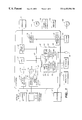
- FIG. 1 is a block diagram of a general operating environment for the present invention.
- FIG. 2 is a perspective view of a mouse of the present invention.
- FIG. 3 is a bottom view of a mouse of the present invention.
- FIG. 4 is an exploded perspective view of a mouse of the present invention.
- FIG. 5 is a side view with portions cut away of a mouse of the present invention.
- FIG. 6 is an expanded view of the cut away portion of FIG. 5 .
- FIG. 7 is a block diagram of a mouse of the present invention.
- FIG. 8 is a circuit diagram of the driver circuit of FIG. 7 .
- FIG. 9 is an image of a display screen useful in describing the functions of the present invention.
- FIG. 10 is block diagram of software components of the present invention.
- FIG. 11 is a flow diagram describing activation of the striking mechanism.
- FIG. 12 is a flow diagram describing the invocation of a striker application.
- FIG. 1 and the related discussion are intended to provide a brief, general description of a suitable computing environment in which the invention may be implemented.
- the invention will be described, at least in part, in the general context of computer-executable instructions, such as program modules, being executed by a personal computer.
- program modules include routine programs, objects, components, data structures, etc. that perform particular tasks or implement particular abstract data types.
- program modules include routine programs, objects, components, data structures, etc. that perform particular tasks or implement particular abstract data types.
- program modules include routine programs, objects, components, data structures, etc. that perform particular tasks or implement particular abstract data types.
- the invention may be practiced with other computer system configurations, including hand-held devices, multiprocessor systems, microprocessor-based or programmable consumer electronics, network PCs, minicomputers, mainframe computers, and the like.
- the invention may also be practiced in distributed computing environments where tasks are performed by remote processing devices that are linked through a communications network.
- program modules may be located in both local and remote memory storage devices.
- an exemplary system for implementing the invention includes a general purpose computing device in the form of a conventional personal computer 20 , including a processing unit (CPU) 21 , a system memory 22 , and a system bus 23 that couples various system components including the system memory 22 to the processing unit 21 .
- the system bus 23 may be any of several types of bus structures including a memory bus or memory controller, a peripheral bus, and a local bus using any of a variety of bus architectures.
- the system memory 22 includes read only memory (ROM) 24 and random access memory (RAM) 25 .
- ROM read only memory
- RAM random access memory
- a basic input/output (BIOS) 26 containing the basic routine that helps to transfer information between elements within the personal computer 20 , such as during start-up, is stored in ROM 24 .
- the personal computer 20 further includes a hard disk drive 27 for reading from and writing to a hard disk (not shown), a magnetic disk drive 28 for reading from or writing to removable magnetic disk 29 , and an optical disk drive 30 for reading from or writing to a removable optical disk 31 such as a CD ROM or other optical media.
- the hard disk drive 27 , magnetic disk drive 28 , and optical disk drive 30 are connected to the system bus 23 by a hard disk drive interface 32 , magnetic disk drive interface 33 , and an optical drive interface 34 , respectively.
- the drives and the associated computer-readable media provide nonvolatile storage of computer readable instructions, data structures, program modules and other data for the personal computer 20 .
- the exemplary environment described herein employs the hard disk, the removable magnetic disk 29 and the removable optical disk 31 , it should be appreciated by those skilled in the art that other types of computer readable media which can store data that is accessible by a computer, such as magnetic cassettes, flash memory cards, digital video disks, Bernoulli cartridges, random access memories (RAMs), read only memory (ROM), and the like, may also be used in the exemplary operating environment.
- RAMs random access memories
- ROM read only memory
- a number of program modules may be stored on the hard disk, magnetic disk 29 , optical disk 31 , ROM 24 or RAM 25 , including an operating system 35 , one or more application programs 36 , other program modules 37 , program data 38 , and device driver 60 .
- the device driver process commands and information entered by a user through an input device, such as keyboard 40 , microphone 43 , mouse 42 , or the like.
- an input device such as keyboard 40 , microphone 43 , mouse 42 , or the like.
- at least one of the input devices includes both a movement transducer and a physical feedback device.
- the physical feedback device is capable of stimulating a localized area of the input device.
- the movement transducer is capable of generating a signal that indicates when a user causes part of the input device to move.
- the physical feedback device and the movement transducer are connected to the processing unit 21 through a serial port interface 46 that is coupled to the system bus 23 , but may be connected by other interfaces, such as a sound card, a parallel port, a game port or a universal serial bus (USB).
- a serial port interface 46 that is coupled to the system bus 23 , but may be connected by other interfaces, such as a sound card, a parallel port, a game port or a universal serial bus (USB).
- a monitor 47 or other type of display device is also connected to the system bus 23 via an interface, such as a video adapter 48 .
- personal computers may typically include other peripheral output devices, such as a speaker 45 and printers (not shown).
- the personal computer 20 may operate in a networked environment using logic connections to one or more remote computers, such as a remote computer 49 .
- the remote computer 49 may be another personal computer, a hand-held device, a server, a router, a network PC, a peer device or other network node, and typically includes many or all of the elements described above relative to the personal computer 20 , although only a memory storage device 50 has been illustrated in FIG. 1 .
- the logic connections depicted in FIG. 1 include a local area network (LAN) 51 and a wide area network (WAN) 52 .
- LAN local area network
- WAN wide area network
- the personal computer 20 When used in a LAN networking environment, the personal computer 20 is connected to the local area network 51 through a network interface or adapter 53 . When used in a WAN networking environment, the personal computer 20 typically includes a modem 54 or other means for establishing communications over the wide area network 52 , such as the Internet.
- the modem 54 which may be internal or external, is connected to the system bus 23 via the serial port interface 46 .
- program modules depicted relative to the personal computer 20 may be stored in the remote memory storage devices. It will be appreciated that the network connections shown are exemplary and other means of establishing a communications link between the computers may be used. For example, a wireless communication link may be established between one or more portions of the network.
- FIG. 2 is a perspective view of a mouse 100 of the present invention.
- Mouse 100 includes a left button 102 , a right button 104 , and a depressible wheel 106 .
- Left button 102 and right button 104 along with a palm-rest 108 , form an outer housing of mouse 100 .
- a connector cable 110 passes through the housing and into the interior of mouse 100 .
- Connector cable 110 includes a number of conductors carrying power and data signals between mouse 100 and the remainder of the computer system.
- FIG. 3 is a bottom view of mouse 100 of FIG. 2 .
- an aperture 122 used in connection with a transducer system that tracks the X and Y movement of mouse 100 across a surface.
- this transducer system includes a track ball that protrudes through aperture 122 and rolls across the surface.
- the transducer system includes optical sensors that track X and Y movement of the mouse based on light that passes through aperture 122 .
- FIG. 4 is an exploded view of mouse 100 of FIGS. 2 and 3.
- mouse 100 includes a housing base 120 that includes aperture 122 .
- Housing base 120 also supports a circuit board 124 that includes a transducer system 126 , a right button switch 130 , a left button switch 132 , a middle button switch 135 , a wheel transducer 131 , a striking mechanism 134 , and a microcontroller 136 .
- Transducer system 126 is the system described above that generates electrical signals based on movement of the mouse. These electrical signals are provided to microcontroller 136 through conductors connected between microcontroller 136 and transducer system 126 .
- Switches 130 and 132 are contacted by the bottom of buttons 104 and 102 , respectively, and are closed when buttons 104 and 102 are respectively depressed.
- switches 130 and 132 include springs that reopen the switches automatically when pressure is released from buttons 104 and 102 , respectively.
- Electrical signals carried on conductors between microcontroller 136 and switches 130 and 132 indicate whether switches 130 and 132 are open or closed.
- Middle button switch 135 is engaged by an arm extension 137 of a depressible carriage 139 , which supports wheel 106 .
- carriage 139 moves downward and closes switch 135 .
- Springs beneath a carriage 139 cause the carriage to lift off switch 135 when force is removed from wheel 106 .
- switch 135 provides an electrical signal to microcontroller 136 indicative of whether the switch is opened or closed.
- An axle of wheel 106 also engages wheel transducer 131 causing a portion of wheel transducer 131 to rotate with wheel 106 .
- Wheel transducer 131 converts this rotational movement into electrical signals that are provided to microcontroller 136 .
- Striking mechanism 134 is connected to microcontroller 136 through a driver circuit 182 and is activated by microcontroller 136 . When activated, a portion of striking mechanism 134 strikes the bottom of button 102 such that a user feels the impact if their finger is positioned on the button. Although shown below button 102 in the embodiment of FIG. 4, in other embodiments striking mechanism 134 is positioned below button 104 and in still other embodiments is positioned below palm rest 108 of a top housing 140 .
- Circuit board 124 is encased between bottom housing 120 and top housing 140 , which includes palm-rest 108 and wheel 106 .
- Buttons 102 and 104 are pivotally connected to top housing 140 through a hinge portion 143 that snap-fits to the underside of top housing 140 , and that flexes to allow buttons 102 and 104 to be depressed.
- FIG. 5 is a side view of mouse 100 showing a cut away section 160 . Within cut away section 160 , striking mechanism 134 and switch 132 can be seen positioned beneath left button 106 .
- FIG. 6 an expanded view of cut away section 160 can be seen showing striking mechanism 134 and switch 132 in greater detail.
- Button 102 is also shown in FIG. 6 and is shown to include strike plate 162 positioned over striking mechanism 134 and button extension 164 positioned over switch 132 .
- Switch 132 includes a base 166 and a raised portion 168 , which moves downward into base 166 when button 102 is pressed toward housing 166 . This movement causes switch 132 to close.
- Striking mechanism 134 includes base 170 and cylinder 172 .
- Cylinder 172 is slideably connected to base 170 and moves vertically in a direction toward strike plate 162 when striking mechanism 134 is activated.
- striking mechanism 134 is a five-volt, one-ampere solenoid that is able to move cylinder 172 so that it strikes strike plate 162 in less than one tenth of a second.
- striking mechanism 134 is a piezoelectric device, while in still other embodiments striking mechanism 134 includes a stepper motor with an eccentric cam positioned to periodically strike the mouse housing or buttons when the stepper motor rotates.
- FIG. 7 is a block diagram showing the layout of circuit board 124 and its connection to the computer system of FIG. 1 .
- FIG. 7 shows the connections discussed above between microcontroller 136 and the plurality of inputs to microcontroller 136 including right button switch 130 , left button switch 132 , middle button switch 135 , wheel transducer 131 and transducer system 126 .
- FIG. 7 also shows a connection 194 between microcontroller 136 and driver circuit 182 .
- microcontroller 136 passes a control signal to driver circuit 182 that causes driver circuit 182 to activate striking mechanism 134 .
- Driver circuit 182 activates striking mechanism 134 through connections 190 and 192 to striking mechanism 134 .
- the activation is powered through connections to positive and negative power supplies 186 and 188 provided by serial port interface 46 .
- Microcontroller 136 is also connected to serial port interface 46 by positive power supply 186 and negative power supply 188 .
- microcontroller 136 is connected to serial port interface 46 by two control lines 200 and 202 .
- control lines 200 and 202 , positive power supply 186 and negative power supply 188 are all bundled together within cable 110 of FIG. 4 .
- the power needed by microcontroller 136 and the power needed to drive striking mechanism 134 is provided along cable 110 so that no additional exterior power source is required to operate the input device.
- FIG. 8 is an expanded circuit diagram of driver circuit 182 of FIG. 7 .
- FIG. 8 shows an embodiment of the present invention that utilizes a solenoid 400 as striking mechanism 134 of FIG. 7 .
- solenoid 400 is activated when a current is drawn through the solenoid by an NPN transistor 416 , which has its collector connected to one terminal of the solenoid.
- the other terminal of solenoid 400 is connected to positive power supply 186 , while the emitter of transistor 416 is connected to negative power supply 186 .
- positive power supply 186 is at 5 volts and negative power supply 188 is at ground.
- a diode 418 is connected across the two terminals of solenoid 400 and provides a current path to discharge current produced by solenoid 400 when transistor 416 is inactive.
- the base of transistor 416 is connected to one terminal of a bias resistor 414 which has its other terminal connected to the collector of a PNP transistor 410 .
- the collector of PNP transistor 410 is also connected to one terminal of a resistor 412 , which has its other terminal connected to negative power supply 188 .
- transistor 410 When transistor 410 is active, a current flows through resistor 412 causing a voltage to develop at the base of transistor 416 that is sufficient to turn on transistor 416 .
- transistor 416 is inactive.
- Transistor 410 has its emitter connected to positive power supply 186 and its base connected to two resistors 408 and 406 .
- Resistor 408 has its second terminal connected to positive power supply 186 and resistor 406 has its second terminal connected to connection 194 which is connected to a pin on microcontroller 136 of FIG. 7 .
- connection 194 When the voltage at connection 194 drops to the negative power supply, current flows through resistors 408 and 406 , which act as a resistance ladder to lower the voltage at the base of transistor 410 so that it becomes active.
- the voltage at connection 194 is at the positive power supply, current does not flow through the resistors and transistor 410 is inactive.
- microcontroller 136 is able to activate and deactivate solenoid 400 through transistors 410 and 416 .
- FIG. 9 is an image of a display produced by computer 20 of FIG. 1 and displayed on monitor 47 .
- the striking mechanism of FIGS. 2, 3 , 4 , 5 , 6 , and 7 is activated when the image of cursor 232 of display 230 crosses a boundary of an object on display 230 .
- the image of cursor 232 is moved across display 230 by an operating system of the computer in response to mouse messages received from a mouse driver that indicate movement of the mouse.
- Examples of objects on the display include a desktop icon such as desktop icon 234 , a window such as window 236 , a pull-down menu such as pull-down menu 238 , a header in a header menu such as header 240 in header menu 242 , an entry in a pull-down menu such as entry 244 , and a select button that can be selected by the user by pressing a mouse button while the cursor is positioned over the select button such as select button 246 .
- the striking mechanism is activated each time the edge of the cursor crosses a boundary of one of these objects.
- a boundary can be defined as a perimeter of the area in which the cursor must be placed to select the object.
- the user feels strike mechanism 134 strike button 102 when the image of cursor 232 crosses the edge of window 236 .
- the user feels strike mechanism 134 strike button 102 again when the cursor enters header menu 242 and when cursor 232 is positioned over header 240 .
- strike mechanism 134 strikes button 102 each time the image of cursor 232 enters or exits the boundaries of an entry in pull-down menu 238 .
- strike mechanism 134 strikes button 102 when the image of cursor 232 exits the boundaries of pull-down menu 238 , window 236 , or select button 246 .
- the activation of the strike mechanism based on these cursor events is controlled by a collection of software components shown in a block diagram in FIG. 10 .
- the interaction of these components is described in flow diagrams in FIGS. 11 and 12.
- mouse driver 400 waits for microcontroller firmware 402 to send a data packet describing the current conditions of mouse 100 . This is shown as wait step 450 of FIG. 11 .
- Microcontroller firmware 402 sends such data packets periodically or whenever the condition of the mouse changes.
- the data packet includes the current state of each of the mouse buttons, a value representing how far the mouse wheel has been rotated and the direction of that rotation, and the X-Y movement of the mouse since the last data packet.
- driver 400 receives a byte of data from microcontroller firmware 402 through serial interface 46 and at step 454 stores the value in processor memory that has been allocated by driver 400 .
- driver 400 stores the data in hardware registers 404 .
- Driver 400 then calls a mini driver 406 of FIG. 10 at step 456 of FIG. 11 .
- Mini driver 406 includes a memory flag, which indicates whether the strike mechanism should be activated. This memory flag is set by an application as discussed further below in connection with step 472 of FIG. 11 .
- mini driver 406 checks the memory flag at step 458 to determine if the strike mechanism should be activated. If the memory flag is set for activation, mini driver 406 sets an actuation value in hardware registers 404 at step 460 . Mini driver 406 then resets the memory flag at step 462 so that during the next call to mini driver 406 , the actuation value is not set in hardware registers 404 .
- driver 400 looks for the actuation value in registers 404 while processing the remainder of the data packet stored in registers 404 . If the actuation value is set at step 466 , driver 400 sends an actuation message to microcontroller firmware 402 at step 468 . In a mouse system that uses a PS/ 2 protocol, the inventors have found that the driver message previously assigned to the “Set Scale 2:1” function may be converted into an “Actuate Striker” function without significant loss in functionality of the mouse.
- microcontroller firmware 402 Based on the “Actuate Striker” message sent by driver 400 , microcontroller firmware 402 activates the striking mechanism.
- microcontroller firmware 402 causes the input connected to driver circuit 182 to oscillate between a digital high and a digital low over a length of time. The period of the oscillations is driven by the type of solenoid and its response time. The length of the oscillations is a matter of preference and has been set between 10 and 100 milliseconds by the present inventors.
- driver 400 can indicate to microcontroller firmware 402 that it should activate the striking mechanism.
- step 472 mouse message hook procedures are invoked. This step is discussed in more detail in FIG. 12 described below.
- the mouse messages are passed to a focus application 414 , which is typically associated with the top-most window on the display in operating systems such as Windows NT®, Windows 95® and Windows 98® from Microsoft Corporation. This is shown as step 474 in FIG. 11 .
- driver 400 returns to state 450 where it waits for the next data packet from microcontroller firmware 402 .
- FIG. 12 provides a more detailed flow diagram of this process as well as a description of how the striker application sets the actuation memory flag in mini driver 406 .
- driver 400 sends mouse messages to the computer's operating system (OS) 408 .
- OS operating system
- operating system 408 is a Windows NT®, a Windows 95®, or Windows 98® brand operating system provided by Microsoft Corporation of Redmond, Washington.
- the mouse messages created by driver 400 are based on values in the data packets received from the mouse. In most operating systems, there are separate messages that indicate if a particular mouse button is up or down and separate messages describing rotation of the wheel. In all of these messages, driver 400 includes the current X-Y coordinates of the display's cursor.
- operating system 408 includes a mouse message hook list that identifies a series of mouse message hook procedures 410 .
- When operating system 408 receives a mouse message it examines its mouse message hook last to determine if any mouse message hook procedures have registered themselves with operating system 408 . If at least one mouse message hook procedure has registered itself with operating system 408 , operating system 408 passes the mouse message to the registered mouse message hook procedure 410 that appears first on the list.
- a striker application 412 registers itself as a mouse message hook procedure to be included in the message hook list.
- OS 408 receives a mouse message, it passes the mouse message to striker application 412 , as shown in step 502 of FIG. 12 .
- Striker application 412 uses the coordinates of the cursor found in the mouse message to determine what the cursor is positioned over in step 504 .
- operating systems such as Windows NT®, Windows 95®, and Windows 98®, this is accomplished using a series of system calls.
- a handle to the current window is retrieved from the system using a WindowFromPoint() call that includes the current coordinates of the cursor.
- the returned window handle is then passed to a number of functions that provide information about the cursor's position within the window or information about the window itself. For example, a call to IsIconic() returns an indication of whether or not the window is minimized and a call to GetClassName() returns an indication of whether the window is a select button. A call to DefWindowProc() returns an indication of which portion of the window the cursor is over. Values returned by DefwindowProc() can indicate that the cursor is over a menu, a maximize or minimize button, a close button, a border, a scroll bar, a title bar, or a client area.
- Striker application 412 also includes a memory value that indicates where the cursor was before the current mouse message. At step 506 of FIG. 12, striker application 412 compares this memory value to the information returned by the various calls to determine if the cursor has crossed a boundary since the last mouse message. For example, striker application 412 determines if the cursor has transitioned onto or off of a minimized window, or onto or off of a select button. Striker application 412 also determines if the cursor has crossed the border of a window, entered the menu bar of a window, or crossed over a particular menu header of a menu bar.
- striker application 412 creates and sends a message to mini driver 406 to set the actuation flag in mini driver 406 . This is shown as step 508 in FIG. 12 .
- the message sent by striker application 412 is an Input/Output Control Message (IOCtl), which is selected from a set of standard IOCtl messages that are associated with current mini drivers.
- IOCtl Input/Output Control Message
- the selected IOCtl message is one that would otherwise not perform an operation in mini driver 406 .
- the IOCtl message “SetDeviceType” can be used.
- mini driver 406 When mini driver 406 receives the message from striker application 412 , it sets the actuation flag in its associated memory location at step 510 . When the next data packet is received by driver 400 , this flag will cause mini driver 406 to set the actuation value in the hardware register so that driver 400 issues the actuation command to the mouse. The process then continues at step 474 of FIG. 11 .
- the present invention improves user efficiency by increasing the feedback provided to the user and allowing the user to make quicker selections.
- an embodiment of the present invention uses a small solenoid to provide physical feedback, it is inexpensive and can be powered through the input device's connection to the computer.
Landscapes
- Engineering & Computer Science (AREA)
- General Engineering & Computer Science (AREA)
- Theoretical Computer Science (AREA)
- Human Computer Interaction (AREA)
- Physics & Mathematics (AREA)
- General Physics & Mathematics (AREA)
- User Interface Of Digital Computer (AREA)
Abstract
Description
Claims (22)
Priority Applications (3)
| Application Number | Priority Date | Filing Date | Title |
|---|---|---|---|
| US09/201,481 US6452586B1 (en) | 1998-11-30 | 1998-11-30 | Computer input device providing tactile feedback |
| AU20326/00A AU2032600A (en) | 1998-11-30 | 1999-11-29 | Computer input device providing tactile feedback |
| PCT/US1999/028148 WO2000033171A1 (en) | 1998-11-30 | 1999-11-29 | Computer input device providing tactile feedback |
Applications Claiming Priority (1)
| Application Number | Priority Date | Filing Date | Title |
|---|---|---|---|
| US09/201,481 US6452586B1 (en) | 1998-11-30 | 1998-11-30 | Computer input device providing tactile feedback |
Publications (1)
| Publication Number | Publication Date |
|---|---|
| US6452586B1 true US6452586B1 (en) | 2002-09-17 |
Family
ID=22745994
Family Applications (1)
| Application Number | Title | Priority Date | Filing Date |
|---|---|---|---|
| US09/201,481 Expired - Lifetime US6452586B1 (en) | 1998-11-30 | 1998-11-30 | Computer input device providing tactile feedback |
Country Status (3)
| Country | Link |
|---|---|
| US (1) | US6452586B1 (en) |
| AU (1) | AU2032600A (en) |
| WO (1) | WO2000033171A1 (en) |
Cited By (16)
| Publication number | Priority date | Publication date | Assignee | Title |
|---|---|---|---|---|
| US6677928B1 (en) * | 1998-07-10 | 2004-01-13 | Computouch A/S | Method and system for improved communication between human and computer |
| US20040183782A1 (en) * | 1998-06-23 | 2004-09-23 | Shahoian Eric J. | Low-cost haptic mouse implementations |
| US6937225B1 (en) | 2000-05-15 | 2005-08-30 | Logitech Europe S.A. | Notification mechanisms on a control device |
| US20060111782A1 (en) * | 2004-11-22 | 2006-05-25 | Orthopedic Development Corporation | Spinal plug for a minimally invasive facet joint fusion system |
| US20060132433A1 (en) * | 2000-04-17 | 2006-06-22 | Virtual Technologies, Inc. | Interface for controlling a graphical image |
| US20060146025A1 (en) * | 2001-10-15 | 2006-07-06 | Logitech Europe S.A. | Mouse with integrated keyplate and housing |
| US20060250352A1 (en) * | 2005-05-05 | 2006-11-09 | Mice Technoligies, Inc. | System and method for improved cursor functionality |
| US20060267944A1 (en) * | 1998-06-23 | 2006-11-30 | Immersion Corporation | Tactile mouse device |
| US20070285216A1 (en) * | 1999-09-28 | 2007-12-13 | Immersion Corporation | Providing enhanced haptic feedback effects |
| US20100085305A1 (en) * | 2008-10-08 | 2010-04-08 | Hsien-Lin Yang | Computer mouse with retractable cable |
| US20100207882A1 (en) * | 1998-06-23 | 2010-08-19 | Immersion Corporation | Haptic Trackball Device |
| JP2010182315A (en) * | 2000-05-24 | 2010-08-19 | Immersion Corp | Haptic device using electroactive polymer |
| US8021392B2 (en) | 2004-11-22 | 2011-09-20 | Minsurg International, Inc. | Methods and surgical kits for minimally-invasive facet joint fusion |
| US8441444B2 (en) | 2000-09-28 | 2013-05-14 | Immersion Corporation | System and method for providing directional tactile sensations |
| US8542105B2 (en) | 2009-11-24 | 2013-09-24 | Immersion Corporation | Handheld computer interface with haptic feedback |
| US20130257730A1 (en) * | 2012-04-02 | 2013-10-03 | Primax Electronics Ltd. | Retractable cable mouse |
Families Citing this family (2)
| Publication number | Priority date | Publication date | Assignee | Title |
|---|---|---|---|---|
| US6243078B1 (en) * | 1998-06-23 | 2001-06-05 | Immersion Corporation | Pointing device with forced feedback button |
| CN112596604B (en) * | 2020-12-09 | 2025-01-17 | Oppo广东移动通信有限公司 | Message sending method, message receiving method, device and electronic device |
Citations (47)
| Publication number | Priority date | Publication date | Assignee | Title |
|---|---|---|---|---|
| US3497668A (en) | 1966-08-25 | 1970-02-24 | Joseph Hirsch | Tactile control system |
| US3919691A (en) | 1971-05-26 | 1975-11-11 | Bell Telephone Labor Inc | Tactile man-machine communication system |
| JPS59119437A (en) | 1982-12-25 | 1984-07-10 | Fujitsu Ltd | Menu selecting system of display picture by mouth device |
| US4655673A (en) | 1983-05-10 | 1987-04-07 | Graham S. Hawkes | Apparatus providing tactile feedback to operators of remotely controlled manipulators |
| US4667182A (en) | 1983-01-28 | 1987-05-19 | International Business Machines Corp. | Stylus or pen with tactile response to user |
| US4687444A (en) | 1986-03-31 | 1987-08-18 | The United States Of America As Represented By The Administrator Of The National Aeronautics & Space Administration | Braille reading system |
| US4712101A (en) * | 1984-12-04 | 1987-12-08 | Cheetah Control, Inc. | Control mechanism for electronic apparatus |
| EP0265011A1 (en) | 1986-10-20 | 1988-04-27 | Océ-Nederland B.V. | Inputting device with tactile feedback |
| US4757302A (en) | 1985-10-16 | 1988-07-12 | Hitachi, Ltd. | Image display apparatus |
| US4795296A (en) | 1986-11-17 | 1989-01-03 | California Institute Of Technology | Hand-held robot end effector controller having movement and force control |
| US4868549A (en) | 1987-05-18 | 1989-09-19 | International Business Machines Corporation | Feedback mouse |
| EP0489469A1 (en) | 1990-12-05 | 1992-06-10 | Koninklijke Philips Electronics N.V. | A data input device for use with a data processing apparatus and a data processing apparatus provided with such a device |
| DE4140780A1 (en) | 1991-12-06 | 1992-09-10 | Matthias Dipl Ing Goebel | Computer input mouse with tactile feedback - is built into push-button keys having EM element providing feedback to fingers |
| JPH04336316A (en) | 1991-05-13 | 1992-11-24 | Nec Corp | System for informing computer internal state information |
| EP0520089A1 (en) | 1991-06-20 | 1992-12-30 | Tandberg Data A/S | Mouse for data entry and control |
| US5185561A (en) | 1991-07-23 | 1993-02-09 | Digital Equipment Corporation | Torque motor as a tactile feedback device in a computer system |
| US5186629A (en) * | 1991-08-22 | 1993-02-16 | International Business Machines Corporation | Virtual graphics display capable of presenting icons and windows to the blind computer user and method |
| US5237311A (en) | 1991-08-01 | 1993-08-17 | Picker International, Inc. | Hingedly supported integrated trackball and selection device |
| US5268674A (en) * | 1992-01-31 | 1993-12-07 | Apple Computer, Inc. | Mechanically latching mouse button |
| US5296871A (en) | 1992-07-27 | 1994-03-22 | Paley W Bradford | Three-dimensional mouse with tactile feedback |
| EP0607580A1 (en) | 1993-01-21 | 1994-07-27 | International Business Machines Corporation | Tactile feedback mechanism for cursor control |
| US5351677A (en) | 1991-04-24 | 1994-10-04 | Olympus Optical Co., Ltd. | Medical system having object information reproduction means for palpation |
| EP0626634A2 (en) | 1993-05-11 | 1994-11-30 | Matsushita Electric Industrial Co., Ltd. | Force-feedback data input device |
| US5389849A (en) | 1993-01-20 | 1995-02-14 | Olympus Optical Co., Ltd. | Tactility providing apparatus and manipulating device using the same |
| EP0662654A1 (en) | 1993-12-30 | 1995-07-12 | International Business Machines Corporation | Program access in a graphical user interface |
| WO1995020787A1 (en) | 1994-01-27 | 1995-08-03 | Exos, Inc. | Multimode feedback display technology |
| DE4341917A1 (en) | 1993-12-06 | 1995-08-17 | Birnbaum Jacek | Electromechanical computer game joystick + |
| WO1995032459A1 (en) | 1994-05-19 | 1995-11-30 | Exos, Inc. | Interactive simulation system including force feedback input device |
| WO1996007965A2 (en) | 1994-09-07 | 1996-03-14 | Philips Electronics N.V. | Virtual workspace with user-programmable tactile feedback |
| WO1996018942A1 (en) | 1994-12-14 | 1996-06-20 | Moore Robert S | Force feedback for virtual reality |
| WO1996025702A2 (en) | 1995-02-13 | 1996-08-22 | Philips Electronics N.V. | A portable data processing apparatus provided with a screen and a gravitation-controlled sensor for screen orientation |
| DE19501439A1 (en) | 1995-01-19 | 1996-09-05 | Meins Juergen Prof Dr Ing | Electromechanical detector of rotation angle for control of vehicle, aircraft or computer input |
| WO1996028777A1 (en) | 1995-03-13 | 1996-09-19 | Philips Electronics N.V. | Vertical translation of mouse or trackball enables truly 3d input |
| US5585823A (en) * | 1994-12-30 | 1996-12-17 | Apple Computer, Inc. | Multi-state one-button computer pointing device |
| US5589854A (en) | 1995-06-22 | 1996-12-31 | Tsai; Ming-Chang | Touching feedback device |
| US5589828A (en) | 1992-03-05 | 1996-12-31 | Armstrong; Brad A. | 6 Degrees of freedom controller with capability of tactile feedback |
| US5619180A (en) | 1993-01-14 | 1997-04-08 | Massachusetts Inst Technology | Apparatus for providing vibrotactile sensory substitution of force feedback |
| US5625576A (en) | 1993-10-01 | 1997-04-29 | Massachusetts Institute Of Technology | Force reflecting haptic interface |
| US5666473A (en) | 1992-10-08 | 1997-09-09 | Science & Technology Corporation & Unm | Tactile computer aided sculpting device |
| US5684722A (en) * | 1994-09-21 | 1997-11-04 | Thorner; Craig | Apparatus and method for generating a control signal for a tactile sensation generator |
| US5691898A (en) | 1995-09-27 | 1997-11-25 | Immersion Human Interface Corp. | Safe and low cost computer peripherals with force feedback for consumer applications |
| US5692956A (en) | 1996-02-09 | 1997-12-02 | Mattel, Inc. | Combination computer mouse and game play control |
| US5699083A (en) * | 1995-11-23 | 1997-12-16 | Shun-Jung Lo | Cursor control device |
| US5717427A (en) * | 1995-07-28 | 1998-02-10 | Sysgration Ltd. | Optical-reflecting decoder modular design mechanism of mouse |
| US5790108A (en) | 1992-10-23 | 1998-08-04 | University Of British Columbia | Controller |
| US5808568A (en) * | 1997-02-27 | 1998-09-15 | Primax Electronics, Ltd. | Finger operated module for generating encoding signals |
| US5986643A (en) * | 1987-03-24 | 1999-11-16 | Sun Microsystems, Inc. | Tactile feedback mechanism for a data processing system |
-
1998
- 1998-11-30 US US09/201,481 patent/US6452586B1/en not_active Expired - Lifetime
-
1999
- 1999-11-29 AU AU20326/00A patent/AU2032600A/en not_active Abandoned
- 1999-11-29 WO PCT/US1999/028148 patent/WO2000033171A1/en not_active Ceased
Patent Citations (50)
| Publication number | Priority date | Publication date | Assignee | Title |
|---|---|---|---|---|
| US3497668A (en) | 1966-08-25 | 1970-02-24 | Joseph Hirsch | Tactile control system |
| US3919691A (en) | 1971-05-26 | 1975-11-11 | Bell Telephone Labor Inc | Tactile man-machine communication system |
| JPS59119437A (en) | 1982-12-25 | 1984-07-10 | Fujitsu Ltd | Menu selecting system of display picture by mouth device |
| US4667182A (en) | 1983-01-28 | 1987-05-19 | International Business Machines Corp. | Stylus or pen with tactile response to user |
| US4655673A (en) | 1983-05-10 | 1987-04-07 | Graham S. Hawkes | Apparatus providing tactile feedback to operators of remotely controlled manipulators |
| US4712101A (en) * | 1984-12-04 | 1987-12-08 | Cheetah Control, Inc. | Control mechanism for electronic apparatus |
| US4757302A (en) | 1985-10-16 | 1988-07-12 | Hitachi, Ltd. | Image display apparatus |
| US4687444A (en) | 1986-03-31 | 1987-08-18 | The United States Of America As Represented By The Administrator Of The National Aeronautics & Space Administration | Braille reading system |
| EP0265011A1 (en) | 1986-10-20 | 1988-04-27 | Océ-Nederland B.V. | Inputting device with tactile feedback |
| US4795296A (en) | 1986-11-17 | 1989-01-03 | California Institute Of Technology | Hand-held robot end effector controller having movement and force control |
| US5986643A (en) * | 1987-03-24 | 1999-11-16 | Sun Microsystems, Inc. | Tactile feedback mechanism for a data processing system |
| US4868549A (en) | 1987-05-18 | 1989-09-19 | International Business Machines Corporation | Feedback mouse |
| EP0489469A1 (en) | 1990-12-05 | 1992-06-10 | Koninklijke Philips Electronics N.V. | A data input device for use with a data processing apparatus and a data processing apparatus provided with such a device |
| US5351677A (en) | 1991-04-24 | 1994-10-04 | Olympus Optical Co., Ltd. | Medical system having object information reproduction means for palpation |
| JPH04336316A (en) | 1991-05-13 | 1992-11-24 | Nec Corp | System for informing computer internal state information |
| EP0520089A1 (en) | 1991-06-20 | 1992-12-30 | Tandberg Data A/S | Mouse for data entry and control |
| US5185561A (en) | 1991-07-23 | 1993-02-09 | Digital Equipment Corporation | Torque motor as a tactile feedback device in a computer system |
| US5237311A (en) | 1991-08-01 | 1993-08-17 | Picker International, Inc. | Hingedly supported integrated trackball and selection device |
| US5186629A (en) * | 1991-08-22 | 1993-02-16 | International Business Machines Corporation | Virtual graphics display capable of presenting icons and windows to the blind computer user and method |
| DE4140780A1 (en) | 1991-12-06 | 1992-09-10 | Matthias Dipl Ing Goebel | Computer input mouse with tactile feedback - is built into push-button keys having EM element providing feedback to fingers |
| US5268674A (en) * | 1992-01-31 | 1993-12-07 | Apple Computer, Inc. | Mechanically latching mouse button |
| US5589828A (en) | 1992-03-05 | 1996-12-31 | Armstrong; Brad A. | 6 Degrees of freedom controller with capability of tactile feedback |
| US5296871A (en) | 1992-07-27 | 1994-03-22 | Paley W Bradford | Three-dimensional mouse with tactile feedback |
| US5506605A (en) | 1992-07-27 | 1996-04-09 | Paley; W. Bradford | Three-dimensional mouse with tactile feedback |
| US5666473A (en) | 1992-10-08 | 1997-09-09 | Science & Technology Corporation & Unm | Tactile computer aided sculpting device |
| US5790108A (en) | 1992-10-23 | 1998-08-04 | University Of British Columbia | Controller |
| US5619180A (en) | 1993-01-14 | 1997-04-08 | Massachusetts Inst Technology | Apparatus for providing vibrotactile sensory substitution of force feedback |
| US5389849A (en) | 1993-01-20 | 1995-02-14 | Olympus Optical Co., Ltd. | Tactility providing apparatus and manipulating device using the same |
| EP0607580A1 (en) | 1993-01-21 | 1994-07-27 | International Business Machines Corporation | Tactile feedback mechanism for cursor control |
| US5555894A (en) | 1993-05-11 | 1996-09-17 | Matsushita Electric Industrial Co., Ltd. | Force sensation exhibiting device, data input device and data input equipment |
| EP0626634A2 (en) | 1993-05-11 | 1994-11-30 | Matsushita Electric Industrial Co., Ltd. | Force-feedback data input device |
| US5625576A (en) | 1993-10-01 | 1997-04-29 | Massachusetts Institute Of Technology | Force reflecting haptic interface |
| DE4341917A1 (en) | 1993-12-06 | 1995-08-17 | Birnbaum Jacek | Electromechanical computer game joystick + |
| EP0662654A1 (en) | 1993-12-30 | 1995-07-12 | International Business Machines Corporation | Program access in a graphical user interface |
| WO1995020787A1 (en) | 1994-01-27 | 1995-08-03 | Exos, Inc. | Multimode feedback display technology |
| WO1995032459A1 (en) | 1994-05-19 | 1995-11-30 | Exos, Inc. | Interactive simulation system including force feedback input device |
| US5643087A (en) | 1994-05-19 | 1997-07-01 | Microsoft Corporation | Input device including digital force feedback apparatus |
| WO1996007965A2 (en) | 1994-09-07 | 1996-03-14 | Philips Electronics N.V. | Virtual workspace with user-programmable tactile feedback |
| US5684722A (en) * | 1994-09-21 | 1997-11-04 | Thorner; Craig | Apparatus and method for generating a control signal for a tactile sensation generator |
| WO1996018942A1 (en) | 1994-12-14 | 1996-06-20 | Moore Robert S | Force feedback for virtual reality |
| US5585823A (en) * | 1994-12-30 | 1996-12-17 | Apple Computer, Inc. | Multi-state one-button computer pointing device |
| DE19501439A1 (en) | 1995-01-19 | 1996-09-05 | Meins Juergen Prof Dr Ing | Electromechanical detector of rotation angle for control of vehicle, aircraft or computer input |
| WO1996025702A2 (en) | 1995-02-13 | 1996-08-22 | Philips Electronics N.V. | A portable data processing apparatus provided with a screen and a gravitation-controlled sensor for screen orientation |
| WO1996028777A1 (en) | 1995-03-13 | 1996-09-19 | Philips Electronics N.V. | Vertical translation of mouse or trackball enables truly 3d input |
| US5589854A (en) | 1995-06-22 | 1996-12-31 | Tsai; Ming-Chang | Touching feedback device |
| US5717427A (en) * | 1995-07-28 | 1998-02-10 | Sysgration Ltd. | Optical-reflecting decoder modular design mechanism of mouse |
| US5691898A (en) | 1995-09-27 | 1997-11-25 | Immersion Human Interface Corp. | Safe and low cost computer peripherals with force feedback for consumer applications |
| US5699083A (en) * | 1995-11-23 | 1997-12-16 | Shun-Jung Lo | Cursor control device |
| US5692956A (en) | 1996-02-09 | 1997-12-02 | Mattel, Inc. | Combination computer mouse and game play control |
| US5808568A (en) * | 1997-02-27 | 1998-09-15 | Primax Electronics, Ltd. | Finger operated module for generating encoding signals |
Non-Patent Citations (6)
| Title |
|---|
| "A Comparison of Tactile, Auditory and Visual Feedback in a Pointing Task Using a Mouse-type Device " by Motoyuki Akamatsu et al., Ergonomics, 1995, vol. 38, No. 4 pp. 816-827. |
| "Braille Computer Mouse With Tactile Position Feedback" IBM Technical Dislosure Bulletin vol. 31, No. 12, May 1989 p. 386. |
| "Feeling and Seeing: Issues in Force Display" by Margaret Minsky et al., Computer Graphics Mar., 1990 pp. 236-244. |
| "Mouse Ball-Actuating Device With Force and Tactile Feedback" IBM Technical Disclosure Bulletin, vol. 32, No. 9B, Feb. 1990 pp. 230-235. |
| "Mouse/Keyboard Concept Incorporating Unique Devices For Controlling CRT Display Cursors"by Nassimbene, IBM Technical Disclosure Bulletin, vol. 27, No. 10B, Mar. 1985 pp. 6299-6305. |
| "Seeing Eye Mouse" IBM Technical Disclosure Bulletin, vol. 28, No. 3, Aug. 1985 pp. 1343-1344. |
Cited By (28)
| Publication number | Priority date | Publication date | Assignee | Title |
|---|---|---|---|---|
| US8462116B2 (en) * | 1998-06-23 | 2013-06-11 | Immersion Corporation | Haptic trackball device |
| USRE40808E1 (en) | 1998-06-23 | 2009-06-30 | Immersion Corporation | Low-cost haptic mouse implementations |
| US20040183782A1 (en) * | 1998-06-23 | 2004-09-23 | Shahoian Eric J. | Low-cost haptic mouse implementations |
| US7423631B2 (en) * | 1998-06-23 | 2008-09-09 | Immersion Corporation | Low-cost haptic mouse implementations |
| US20060267944A1 (en) * | 1998-06-23 | 2006-11-30 | Immersion Corporation | Tactile mouse device |
| US9465438B2 (en) | 1998-06-23 | 2016-10-11 | Immersion Corporation | System and method for outputting haptic effects in a mouse device |
| US20100207882A1 (en) * | 1998-06-23 | 2010-08-19 | Immersion Corporation | Haptic Trackball Device |
| US6677928B1 (en) * | 1998-07-10 | 2004-01-13 | Computouch A/S | Method and system for improved communication between human and computer |
| US20070285216A1 (en) * | 1999-09-28 | 2007-12-13 | Immersion Corporation | Providing enhanced haptic feedback effects |
| US9492847B2 (en) | 1999-09-28 | 2016-11-15 | Immersion Corporation | Controlling haptic sensations for vibrotactile feedback interface devices |
| US7821493B2 (en) | 1999-09-28 | 2010-10-26 | Immersion Corporation | Providing enhanced haptic feedback effects |
| US20060132433A1 (en) * | 2000-04-17 | 2006-06-22 | Virtual Technologies, Inc. | Interface for controlling a graphical image |
| US7821498B2 (en) | 2000-04-17 | 2010-10-26 | Immersion Corporation | Interface for controlling a graphical image |
| US6937225B1 (en) | 2000-05-15 | 2005-08-30 | Logitech Europe S.A. | Notification mechanisms on a control device |
| JP2010182315A (en) * | 2000-05-24 | 2010-08-19 | Immersion Corp | Haptic device using electroactive polymer |
| US8441444B2 (en) | 2000-09-28 | 2013-05-14 | Immersion Corporation | System and method for providing directional tactile sensations |
| US8134533B2 (en) * | 2001-10-15 | 2012-03-13 | Logitech Europe S.A. | Mouse with integrated keyplate and housing |
| US20060146025A1 (en) * | 2001-10-15 | 2006-07-06 | Logitech Europe S.A. | Mouse with integrated keyplate and housing |
| US8021392B2 (en) | 2004-11-22 | 2011-09-20 | Minsurg International, Inc. | Methods and surgical kits for minimally-invasive facet joint fusion |
| US7708761B2 (en) * | 2004-11-22 | 2010-05-04 | Minsurg International, Inc. | Spinal plug for a minimally invasive facet joint fusion system |
| US20060111782A1 (en) * | 2004-11-22 | 2006-05-25 | Orthopedic Development Corporation | Spinal plug for a minimally invasive facet joint fusion system |
| US20060250352A1 (en) * | 2005-05-05 | 2006-11-09 | Mice Technoligies, Inc. | System and method for improved cursor functionality |
| US8077149B2 (en) * | 2008-10-08 | 2011-12-13 | Kui-Hsien Huang | Computer mouse with retractable cable including a circuit board within a cable reeling device |
| US20100085305A1 (en) * | 2008-10-08 | 2010-04-08 | Hsien-Lin Yang | Computer mouse with retractable cable |
| US8542105B2 (en) | 2009-11-24 | 2013-09-24 | Immersion Corporation | Handheld computer interface with haptic feedback |
| US9227137B2 (en) | 2009-11-24 | 2016-01-05 | Immersion Corporation | Handheld computer interface with haptic feedback |
| US20130257730A1 (en) * | 2012-04-02 | 2013-10-03 | Primax Electronics Ltd. | Retractable cable mouse |
| US8643601B2 (en) * | 2012-04-02 | 2014-02-04 | Primax Electronics Ltd. | Retractable cable mouse |
Also Published As
| Publication number | Publication date |
|---|---|
| WO2000033171A1 (en) | 2000-06-08 |
| AU2032600A (en) | 2000-06-19 |
Similar Documents
| Publication | Publication Date | Title |
|---|---|---|
| US6452586B1 (en) | Computer input device providing tactile feedback | |
| US7283121B2 (en) | Input device with forward/backward control | |
| US6903730B2 (en) | In-air gestures for electromagnetic coordinate digitizers | |
| US6664991B1 (en) | Method and apparatus for providing context menus on a pen-based device | |
| US5436637A (en) | Graphical user interface system and methods for improved user feedback | |
| US6396477B1 (en) | Method of interacting with a computer using a proximity sensor in a computer input device | |
| US6456275B1 (en) | Proximity sensor in a computer input device | |
| US6005570A (en) | Graphical user interface system and methods for improved user feedback | |
| US6791536B2 (en) | Simulating gestures of a pointing device using a stylus and providing feedback thereto | |
| US6992656B2 (en) | Computer mouse with data retrieval and input functionalities | |
| US5917486A (en) | System and method for client program control of a computer display cursor | |
| US7319454B2 (en) | Two-button mouse input using a stylus | |
| US6609146B1 (en) | System for automatically switching between two executable programs at a user's computer interface during processing by one of the executable programs | |
| KR100726693B1 (en) | Information processing method and apparatus | |
| US5617526A (en) | Operating system provided notification area for displaying visual notifications from application programs | |
| US6903722B2 (en) | Computer system having a plurality of input devices and associated double-click parameters | |
| US6208343B1 (en) | Graphical user interface scroll bar that provides varied levels of access granularity | |
| US20150145785A1 (en) | Recognizing multiple input point gestures | |
| JPH0580009B2 (en) | ||
| US7002558B2 (en) | Mode hinting and switching | |
| JPH05216648A (en) | Graphical user interface and method for recognizing gesture | |
| US6181338B1 (en) | Apparatus and method for managing windows in graphical user interface environment | |
| WO1998043202A1 (en) | Button wheel pointing device for notebook pcs | |
| US20030139932A1 (en) | Control apparatus | |
| JPH11224163A (en) | Information processor and cursor display control method |
Legal Events
| Date | Code | Title | Description |
|---|---|---|---|
| AS | Assignment |
Owner name: MICROSOFT CORPORATION, WASHINGTON Free format text: ASSIGNMENT OF ASSIGNORS INTEREST;ASSIGNORS:HOLMDAHL, TODD E.;VON FUCHS, ERIK;HOONING, MICHAEL R.;REEL/FRAME:009620/0124;SIGNING DATES FROM 19981123 TO 19981125 |
|
| STCF | Information on status: patent grant |
Free format text: PATENTED CASE |
|
| CC | Certificate of correction | ||
| FPAY | Fee payment |
Year of fee payment: 4 |
|
| FPAY | Fee payment |
Year of fee payment: 8 |
|
| FPAY | Fee payment |
Year of fee payment: 12 |
|
| AS | Assignment |
Owner name: MICROSOFT TECHNOLOGY LICENSING, LLC, WASHINGTON Free format text: ASSIGNMENT OF ASSIGNORS INTEREST;ASSIGNOR:MICROSOFT CORPORATION;REEL/FRAME:034541/0001 Effective date: 20141014 |
|
| AS | Assignment |
Owner name: MICROSOFT CORPORATION, WASHINGTON Free format text: ASSIGNMENT OF ASSIGNORS INTEREST;ASSIGNOR:MICROSOFT TECHNOLOGY LICENSING, LLC;REEL/FRAME:036930/0248 Effective date: 20150128 |
|
| AS | Assignment |
Owner name: MICROSOFT TECHNOLOGY LICENSING, LLC, WASHINGTON Free format text: ASSIGNMENT OF ASSIGNORS INTEREST;ASSIGNOR:MICROSOFT CORPORATION;REEL/FRAME:041517/0431 Effective date: 20170123 |
|
| AS | Assignment |
Owner name: MICROSOFT TECHNOLOGY LICENSING, LLC, WASHINGTON Free format text: CORRECTIVE ASSIGNMENT TO CORRECT THE PATENT NUMBER 6030518 PREVIOUSLY RECORDED ON REEL 041517 FRAME 0431. ASSIGNOR(S) HEREBY CONFIRMS THE ASSIGNMENT;ASSIGNOR:MICROSOFT CORPORATION;REEL/FRAME:042334/0251 Effective date: 20170123 |