US6448734B1 - Method for current regulation of permanently excited synchronous motors for guided missiles having an electromechanical actuating drive for the rudder - Google Patents
Method for current regulation of permanently excited synchronous motors for guided missiles having an electromechanical actuating drive for the rudder Download PDFInfo
- Publication number
- US6448734B1 US6448734B1 US09/785,661 US78566101A US6448734B1 US 6448734 B1 US6448734 B1 US 6448734B1 US 78566101 A US78566101 A US 78566101A US 6448734 B1 US6448734 B1 US 6448734B1
- Authority
- US
- United States
- Prior art keywords
- current
- angle
- measured
- rudder
- synchronous motors
- Prior art date
- Legal status (The legal status is an assumption and is not a legal conclusion. Google has not performed a legal analysis and makes no representation as to the accuracy of the status listed.)
- Expired - Lifetime
Links
Images


Classifications
-
- H—ELECTRICITY
- H02—GENERATION; CONVERSION OR DISTRIBUTION OF ELECTRIC POWER
- H02P—CONTROL OR REGULATION OF ELECTRIC MOTORS, ELECTRIC GENERATORS OR DYNAMO-ELECTRIC CONVERTERS; CONTROLLING TRANSFORMERS, REACTORS OR CHOKE COILS
- H02P6/00—Arrangements for controlling synchronous motors or other dynamo-electric motors using electronic commutation dependent on the rotor position; Electronic commutators therefor
- H02P6/28—Arrangements for controlling current
Definitions
- the invention relates to a method for regulating the current flow in a permanently excited synchronous motor for a guided missile having an electromechanical actuating drive for the rudder.
- the high-frequency spindle drive must be of compact design.
- One object of the invention is to provide a method of current regulation which results in maximum utilization of the machine at high revolutions.
- Another object of the invention is to provide a miniaturized drive that achieves excellent circular acceleration.
- the phase position of the impressed machine current must be corrected such that the machine develops maximum torque.
- the method must carry out a robust compensation of the phase-frequency characteristic at high rotational speeds.
- computing time requirements of the method and the requirements concerning scanning time of the control algorithm are to be kept as low as possible.
- a measured magnitude of a current-space pointer is determined and an error value for the current is added to a desired value of the amount via a correction regulator;
- a measurement for the angle error is determined and added to the desired angle value via a correction regulator.
- FIG. 1 is a block diagram of the control circuit for carrying out the method according to the invention
- FIG. 2 is a detailed representation of the block “polar current/voltage commands” of FIG. 1;
- FIG. 3 is a functional block diagram of the correction regulator of FIG. 1;
- FIG. 4 is a functional block diagram of the phase voltage regulator of FIG. 1 .
- the current-regulating method according to the invention causes the commanded current I R to be guided orthogonally to the magnet-wheel flow for maximum torque development. Calculations are performed in a polar coordinate system with reference to the rotor (field-oriented control).
- FIG. 1 shows a block diagram of the control circuit with a circuit arrangement for implementing the method.
- the permanently excited synchronous motor 11 is connected on the input side to a final control element 4 .
- the final control element itself comprises a d.c. voltage intermediate circuit converter 6 which is driven by a pulse-width modulator 5 .
- a resolver 10 is rigidly coupled to the shaft 12 of the synchronous machine 11 .
- i AC
- (2) ⁇ C sign ⁇ ( i R ) ⁇ ⁇ 2 + ⁇ EL + ⁇ T ( 3 )
- ⁇ T is the angle for dead-time correction in the digital implementation of the method
- Zp is the pole-pair number of the synchronous motor
- ⁇ EL is the electrical magnet wheel angle:
- u AC K CDO ⁇ ⁇ 2 ⁇ ⁇ ⁇ t ⁇ ⁇ M ( 6 )
- ⁇ C ⁇ 2 + ⁇ EL + ⁇ T ( 7 )
- phase voltages of the three-phase system are calculated after correction of the amount and the phase in block 2 /FIG. 1 “desired values of phase voltage”:
- i 1C i AK ⁇ cos( ⁇ K ) (8)
- i 2 ⁇ C i AK ⁇ cos ⁇ ( ⁇ K + 2 ⁇ ⁇ 3 ) ( 9 )
- i 3 ⁇ C i AK ⁇ cos ⁇ ( ⁇ K - 2 ⁇ ⁇ 3 ) ( 10 )
- the amount i AK and the angle ⁇ K result from adding the commanded values with the output values of correction regulator 9 / according to FIG. 1 :
- u A1C u AC ⁇ cos( ⁇ c ) (13)
- u A2C u AC ⁇ cos ⁇ ( ⁇ C + 2 ⁇ ⁇ 3 ) ( 14 )
- u A3C u AC ⁇ cos ⁇ ( ⁇ C - 2 ⁇ ⁇ 3 ) ( 15 )
- the current amount correction value ⁇ i K and the correction value of the current angle ⁇ K are the output values of two PI regulators;
- FIG. 3 shows a function diagram.
- Values for the current error ⁇ i A and the angle error i ⁇ in FIG. 3 are determined in block 7 /FIG. 1 “Polar current measuring values/errors”.
- the magnitude of the measured space-current pointer i AM is formed from the measured values i 1M and i 2M of the phase voltage:
- i XS i 1M (16)
- i YS - 2 3 ⁇ ( i 2 ⁇ M + 1 2 ⁇ i 1 ⁇ M ) ( 17 )
- i AM i XS 2 + i YS 2 ( 18 )
- FIG. 4 is a function diagram that shows the phase voltage regulator 3 /FIG. 1 .
- R W designates the ohmic resistance of a phase of the machine 11 /FIG. 1 .
- the commanded phase voltages according to FIG. 4 result from:
- u 1C u A1C +R W ⁇ K 1 ⁇ ( i 1C ⁇ K 2 ⁇ i 1M ) (22)
- u 2C u A2C +R W ⁇ K 1 ⁇ ( i 2C ⁇ K 2 ⁇ i 2M ) (23)
- u 3C u A3C +R W ⁇ K 1 ⁇ ( i 3C ⁇ K 2 ⁇ i 3M ) (24)
- the method according to the invention can be implemented with little hardware expenditure and in a compact design size, even for high rotational speeds of >10,000 min ⁇ 1 .
- Current-regulating methods used previously which involve frequency response compensation in polar coordinates, cannot be used with synchronous motors; that is, explicit determination of the angle of the space-current pointer fails in cases where the measured current disappears.
Landscapes
- Engineering & Computer Science (AREA)
- Power Engineering (AREA)
- Control Of Ac Motors In General (AREA)
- Control Of Multiple Motors (AREA)
- Control Of Motors That Do Not Use Commutators (AREA)
Abstract
In a method for current regulation of permanently excited synchronous motors for guided missiles with an electromechanical actuating drive for the rudder, the commanded current is always guided orthogonally to the magnet-wheel flow. Further:
a) from measured current of two voltage phases, a measured magnitude of a current-space pointer is determined and an error value for the current is added to a desired value of the amount via a correction regulator; and
b) from measured current of two voltage phases as well as from the angle command of the current-space pointer, a measurement for the angle error is determined and added to the desired angle value via a correction regulator.
The method according to the invention can be implemented with little hardware expenditure and in a compact design size, even for high rotational speeds of >10,000 min−1. Current-regulating methods used heretofore, which involve frequency response compensation in polar coordinates, cannot be used with synchronous motors, i.e. explicit determination of the angle of the space-current pointer fails in cases where the measured current disappears.
Description
This application claims the priority of German patent document 100 07 120.1, filed Feb. 17, 2000, the disclosure of which is expressly incorporated by reference herein.
The invention relates to a method for regulating the current flow in a permanently excited synchronous motor for a guided missile having an electromechanical actuating drive for the rudder.
As a result of ever more stringent requirements in respect of dynamics, weight and volume, the use of electromechanical rudder actuating systems in modern guided missiles is increasing. For this purpose, permanently excited synchronous machines with high energy magnets are used as servomotors, due to their low axial mass moment of inertia, their excellent wear resistance and their substantial energy density. For space reasons and because of the low axial mass moment of inertia of the arrangement, force is transmitted to the rudder via a roller spindle driven arrangement, in which the spindle itself is directly linked in a rigid connection to the rotor of the machine. Such a device is described in detail in German patent document DE 196 35 847 C2.
Due to the transmission ratio between the machine and the rudder, the high-frequency spindle drive must be of compact design.
One object of the invention, therefore, is to provide a method of current regulation which results in maximum utilization of the machine at high revolutions.
Another object of the invention is to provide a miniaturized drive that achieves excellent circular acceleration.
To this end, for a given amount of the commanded armature current, the phase position of the impressed machine current must be corrected such that the machine develops maximum torque. In spite of extraneous interference effects, the method must carry out a robust compensation of the phase-frequency characteristic at high rotational speeds. In the case of implementation on a microprocessor, computing time requirements of the method and the requirements concerning scanning time of the control algorithm, are to be kept as low as possible.
These and other advantages are achieved by the method according to the invention, in which the command current is always guided orthogonally to the magnet-wheel flow. Further:
a) from measured current of two voltage phases, a measured magnitude of a current-space pointer is determined and an error value for the current is added to a desired value of the amount via a correction regulator; and
b) from the measured current of two voltage phases as well as from the angle command of the current-space pointer, a measurement for the angle error is determined and added to the desired angle value via a correction regulator.
Other objects, advantages and novel features of the present invention will become apparent from the following detailed description of the invention when considered in conjunction with the accompanying drawings.
FIG. 1 is a block diagram of the control circuit for carrying out the method according to the invention;
FIG. 2 is a detailed representation of the block “polar current/voltage commands” of FIG. 1;
FIG. 3 is a functional block diagram of the correction regulator of FIG. 1; and
FIG. 4 is a functional block diagram of the phase voltage regulator of FIG. 1.
The current-regulating method according to the invention causes the commanded current IR to be guided orthogonally to the magnet-wheel flow for maximum torque development. Calculations are performed in a polar coordinate system with reference to the rotor (field-oriented control).
FIG. 1 shows a block diagram of the control circuit with a circuit arrangement for implementing the method.
In this embodiment, the permanently excited synchronous motor 11 is connected on the input side to a final control element 4. The final control element itself comprises a d.c. voltage intermediate circuit converter 6 which is driven by a pulse-width modulator 5. For measuring the position of the magnet wheel, a resolver 10 is rigidly coupled to the shaft 12 of the synchronous machine 11. In transmitter signal processing 8, the magnet wheel position angle γM is calculated as follows: 
Conversion of the current command and the electromotive force compensation takes place in block 1 “polar current/voltage commands”, as illustrated in FIG. 2. The magnitude iAC and phase angle εC of the commanded current iR is calculated from:

In this, εT is the angle for dead-time correction in the digital implementation of the method, Zp is the pole-pair number of the synchronous motor and γEL is the electrical magnet wheel angle:

The voltage μAC and the angle ρC together form the calculated counter electromotive force of the synchronous motor: 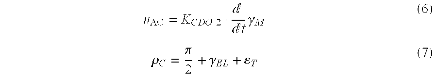
The desired values of phase voltages of the three-phase system are calculated after correction of the amount and the phase in block 2/FIG. 1 “desired values of phase voltage”:

The amount iAK and the angle εK result from adding the commanded values with the output values of correction regulator 9/ according to FIG. 1:
Representation of the counter electromotive force in the three-phase system is as follows:

In the correction regulator 9/FIG. 1, the current amount correction value δiK and the correction value of the current angle δεK are the output values of two PI regulators; FIG. 3 shows a function diagram.
Values for the current error δiA and the angle error iδε in FIG. 3 are determined in block 7/FIG. 1 “Polar current measuring values/errors”. For this purpose, the magnitude of the measured space-current pointer iAM is formed from the measured values i1M and i2M of the phase voltage:


The error amount of the current then results for:
The fraction iD of the measured current iAM in longitudinal direction relative to the axis of the magnet wheel is used as the measure for the angle error. It must be pointed out that as a rule, direct calculation of the angle εM of the measured current by calculation from the atan2 function is too intensive in computing time. Furthermore, in the case of iAM=0 the calculation fails because in this case the angle εM is indeterminate. Thus we arrive at the following:
In addition, the value calculated in equation (20) corresponds to:
FIG. 4 is a function diagram that shows the phase voltage regulator 3/FIG. 1. The amplifications K1 and K2 in FIG. 4 are to be set such that in the case of a fixed-voltage rotor of the synchronous motor 11/FIG. 1, the measured current iAM asymptotically follows the commanded current iR in the case of iR being stepped. From this, amplification K2 is determined as follows: 
In FIG. 4, RW designates the ohmic resistance of a phase of the machine 11/FIG. 1.
The commanded phase voltages according to FIG. 4 result from:
The method according to the invention can be implemented with little hardware expenditure and in a compact design size, even for high rotational speeds of >10,000 min−1. Current-regulating methods used previously, which involve frequency response compensation in polar coordinates, cannot be used with synchronous motors; that is, explicit determination of the angle of the space-current pointer fails in cases where the measured current disappears.
The foregoing disclosure has been set forth merely to illustrate the invention and is not intended to be limiting. Since modifications of the disclosed embodiments incorporating the spirit and substance of the invention may occur to persons skilled in the art, the invention should be construed to include everything within the scope of the appended claims and equivalents thereof.
Claims (2)
1. A method for current regulation in a permanently excited synchronous motor, in which a commanded current iR is controlled orthogonally to a magnet-wheel flow, wherein:
from measured current of two voltage phases i1M and i2M a magnitude for a current-space pointer iAM is determined according to 
with the value iYS being determined according to 
an amount of a current error is determined according to
the amount of the current error is added to the absolute value |iR| in a correction regulation;
from the measured current of two voltage phases i1M and i2M and an angle command εC of the current-space pointer, a measurement is determined for angle error, according to
and
the angle error is added to the desired angle value via a correction regulation εC.
2. A method for current regulation in a permanently excited synchronous motor, according to claim 1 , wherein said motor is adapted to actuate a rudder of a missile.
Applications Claiming Priority (3)
| Application Number | Priority Date | Filing Date | Title |
|---|---|---|---|
| DE10007120 | 2000-02-17 | ||
| DE10007120A DE10007120B4 (en) | 2000-02-17 | 2000-02-17 | Current regulation of permanent-magnet synchronous motors for guided missiles with electromechanical rudder actuator |
| DE10007120.1 | 2000-02-17 |
Publications (2)
| Publication Number | Publication Date |
|---|---|
| US20020047680A1 US20020047680A1 (en) | 2002-04-25 |
| US6448734B1 true US6448734B1 (en) | 2002-09-10 |
Family
ID=7631234
Family Applications (1)
| Application Number | Title | Priority Date | Filing Date |
|---|---|---|---|
| US09/785,661 Expired - Lifetime US6448734B1 (en) | 2000-02-17 | 2001-02-20 | Method for current regulation of permanently excited synchronous motors for guided missiles having an electromechanical actuating drive for the rudder |
Country Status (4)
| Country | Link |
|---|---|
| US (1) | US6448734B1 (en) |
| DE (1) | DE10007120B4 (en) |
| FR (1) | FR2805414B1 (en) |
| GB (1) | GB2363865B (en) |
Families Citing this family (4)
| Publication number | Priority date | Publication date | Assignee | Title |
|---|---|---|---|---|
| WO2008052388A1 (en) * | 2006-10-31 | 2008-05-08 | Byd Company Limited | Control method of electromotor |
| DE102008007100A1 (en) * | 2008-02-01 | 2009-08-06 | Robert Bosch Gmbh | Device i.e. pre-controller, for e.g. linear actuator, in field-oriented co-ordinate system, has synchronous machine, where manipulated variable over plugged by device over integral divider of electrical angle in circuit |
| DE102014212554A1 (en) * | 2014-06-30 | 2015-12-31 | Siemens Aktiengesellschaft | Diagnosis of a drive system and drive system |
| CN117118292B (en) * | 2023-08-11 | 2024-05-03 | 浙江大学 | Torque pulsation suppression method for iterative learning single-rotor compressor controller |
Citations (11)
| Publication number | Priority date | Publication date | Assignee | Title |
|---|---|---|---|---|
| US3642233A (en) * | 1964-06-04 | 1972-02-15 | Telecommunications Sa | System for the optical automatic and autonomous guiding of self-rotating missiles |
| US3946691A (en) * | 1973-10-17 | 1976-03-30 | Metal Marine Pilot, Inc. | Autopilot employing improved hall-effect direction sensor |
| US3972224A (en) * | 1974-05-14 | 1976-08-03 | Maxwell Ingram | Shaft efficiency monitoring system |
| US4612488A (en) * | 1984-06-20 | 1986-09-16 | Kernforschungsanlage Julich Gesellschaft Mit Beschrankter Haftung | Apparatus for controlling the directional orientation of a radiation receiver device to a light source |
| US4683407A (en) * | 1985-04-02 | 1987-07-28 | Plessey Incorporated | Authority limiter |
| US4991429A (en) * | 1989-12-28 | 1991-02-12 | Westinghouse Electric Corp. | Torque angle and peak current detector for synchronous motors |
| US5649422A (en) * | 1994-01-29 | 1997-07-22 | Jungheinrich Aktiengesellschaft | Hydraulic lift apparatus for a battery driven lift truck |
| US5670856A (en) * | 1994-11-07 | 1997-09-23 | Alliedsignal Inc. | Fault tolerant controller arrangement for electric motor driven apparatus |
| DE19635847A1 (en) | 1996-09-04 | 1998-03-12 | Daimler Benz Aerospace Ag | Guided missile with ramjet drive |
| US6075332A (en) * | 1998-05-14 | 2000-06-13 | Mccann; Roy A. | Predictive conductive angle motor control system for brake-by-wire application |
| US6362590B2 (en) * | 1995-08-04 | 2002-03-26 | The Boeing Company | Starting of synchronous machine without rotor position or speed measurement |
Family Cites Families (5)
| Publication number | Priority date | Publication date | Assignee | Title |
|---|---|---|---|---|
| US4361791A (en) * | 1981-05-12 | 1982-11-30 | General Electric Company | Apparatus for controlling a PWM inverter-permanent magnet synchronous motor drive |
| JPH04505996A (en) * | 1989-05-31 | 1992-10-15 | シーメンス アクチエンゲゼルシヤフト | Method for compensating phase and amplitude responses between setpoint and actual values of polyphases and circuit arrangement for implementing this method |
| JP3226253B2 (en) * | 1995-09-11 | 2001-11-05 | 株式会社東芝 | Control device for permanent magnet synchronous motor |
| US5838122A (en) * | 1996-02-08 | 1998-11-17 | Seiberco Incorporated | Motor initialization method and apparatus |
| DE19725136C2 (en) * | 1997-06-13 | 2001-01-11 | Siemens Ag | Method and device for current control of a field-oriented, permanently excited synchronous machine with trapezoidal EMF |
-
2000
- 2000-02-17 DE DE10007120A patent/DE10007120B4/en not_active Expired - Fee Related
-
2001
- 2001-01-22 GB GB0101594A patent/GB2363865B/en not_active Expired - Fee Related
- 2001-02-12 FR FR0101882A patent/FR2805414B1/en not_active Expired - Fee Related
- 2001-02-20 US US09/785,661 patent/US6448734B1/en not_active Expired - Lifetime
Patent Citations (11)
| Publication number | Priority date | Publication date | Assignee | Title |
|---|---|---|---|---|
| US3642233A (en) * | 1964-06-04 | 1972-02-15 | Telecommunications Sa | System for the optical automatic and autonomous guiding of self-rotating missiles |
| US3946691A (en) * | 1973-10-17 | 1976-03-30 | Metal Marine Pilot, Inc. | Autopilot employing improved hall-effect direction sensor |
| US3972224A (en) * | 1974-05-14 | 1976-08-03 | Maxwell Ingram | Shaft efficiency monitoring system |
| US4612488A (en) * | 1984-06-20 | 1986-09-16 | Kernforschungsanlage Julich Gesellschaft Mit Beschrankter Haftung | Apparatus for controlling the directional orientation of a radiation receiver device to a light source |
| US4683407A (en) * | 1985-04-02 | 1987-07-28 | Plessey Incorporated | Authority limiter |
| US4991429A (en) * | 1989-12-28 | 1991-02-12 | Westinghouse Electric Corp. | Torque angle and peak current detector for synchronous motors |
| US5649422A (en) * | 1994-01-29 | 1997-07-22 | Jungheinrich Aktiengesellschaft | Hydraulic lift apparatus for a battery driven lift truck |
| US5670856A (en) * | 1994-11-07 | 1997-09-23 | Alliedsignal Inc. | Fault tolerant controller arrangement for electric motor driven apparatus |
| US6362590B2 (en) * | 1995-08-04 | 2002-03-26 | The Boeing Company | Starting of synchronous machine without rotor position or speed measurement |
| DE19635847A1 (en) | 1996-09-04 | 1998-03-12 | Daimler Benz Aerospace Ag | Guided missile with ramjet drive |
| US6075332A (en) * | 1998-05-14 | 2000-06-13 | Mccann; Roy A. | Predictive conductive angle motor control system for brake-by-wire application |
Also Published As
| Publication number | Publication date |
|---|---|
| FR2805414B1 (en) | 2004-01-23 |
| GB0101594D0 (en) | 2001-03-07 |
| US20020047680A1 (en) | 2002-04-25 |
| DE10007120A1 (en) | 2001-08-30 |
| GB2363865A (en) | 2002-01-09 |
| DE10007120B4 (en) | 2007-04-12 |
| FR2805414A1 (en) | 2001-08-24 |
| GB2363865B (en) | 2004-02-04 |
Similar Documents
| Publication | Publication Date | Title |
|---|---|---|
| US7548038B2 (en) | Controller for motor | |
| US8106618B2 (en) | Method and device for calibrating a position sensor placed on a shaft of a permanent magnet synchronous motor | |
| US7463006B2 (en) | Motor and drive control device therefor | |
| US7659688B2 (en) | Method and system for resolver alignment in electric motor system | |
| CN103051277B (en) | Parameter estimating apparatus for permanent magnet synchronous motor driving system | |
| US7560896B2 (en) | Vector control apparatus for permanent magnet motor | |
| US7583048B2 (en) | Controller for motor | |
| EP1583217B1 (en) | Motor drive-controlling device and electric power-steering device | |
| US6738718B2 (en) | Method and apparatus for measuring torque and flux current in a synchronous motor | |
| EP1347568B1 (en) | Stepping motor driver | |
| US20070222405A1 (en) | Controller for motor | |
| CN101383581A (en) | Absolute position sensor for field-oriented control of an induction motor | |
| US10807640B2 (en) | Motor control apparatus and method of motor driven power steering system | |
| CN100369375C (en) | Motor and drive control device therefor | |
| EP1793487A1 (en) | Vector controller of induction motor | |
| US6448734B1 (en) | Method for current regulation of permanently excited synchronous motors for guided missiles having an electromechanical actuating drive for the rudder | |
| US6747433B2 (en) | Stepping motor controller | |
| CN117792178A (en) | Motor control method, apparatus and computer readable storage medium | |
| JP3804686B2 (en) | Motor drive control device and electric power steering device | |
| JP3682543B2 (en) | Control method of permanent magnet type synchronous motor | |
| CN110557059B (en) | Motor stalling method and device | |
| US20240424910A1 (en) | Method for determining a resolver offset | |
| FI112300B (en) | Method and apparatus for controlling a synchronous permanent magnet motor | |
| JP2006217795A (en) | Motor and its drive control device | |
| EP3226405B1 (en) | Apparatus for correcting current reference |
Legal Events
| Date | Code | Title | Description |
|---|---|---|---|
| AS | Assignment |
Owner name: LFK LENKFLUGKOERPERSYSTEME GMBH, GERMANY Free format text: ASSIGNMENT OF ASSIGNORS INTEREST;ASSIGNORS:FRENZEL, BERNHARD;KILGER, FIDBERT;REEL/FRAME:012011/0723 Effective date: 20010307 |
|
| FEPP | Fee payment procedure |
Free format text: PAYOR NUMBER ASSIGNED (ORIGINAL EVENT CODE: ASPN); ENTITY STATUS OF PATENT OWNER: LARGE ENTITY |
|
| STCF | Information on status: patent grant |
Free format text: PATENTED CASE |
|
| FPAY | Fee payment |
Year of fee payment: 4 |
|
| FPAY | Fee payment |
Year of fee payment: 8 |
|
| FPAY | Fee payment |
Year of fee payment: 12 |