US643082A - Core breaker and lifter for rock-drills. - Google Patents
Core breaker and lifter for rock-drills. Download PDFInfo
- Publication number
- US643082A US643082A US69160498A US1898691604A US643082A US 643082 A US643082 A US 643082A US 69160498 A US69160498 A US 69160498A US 1898691604 A US1898691604 A US 1898691604A US 643082 A US643082 A US 643082A
- Authority
- US
- United States
- Prior art keywords
- drill
- rod
- head
- core
- cutting
- Prior art date
- Legal status (The legal status is an assumption and is not a legal conclusion. Google has not performed a legal analysis and makes no representation as to the accuracy of the status listed.)
- Expired - Lifetime
Links
Images


Classifications
-
- E—FIXED CONSTRUCTIONS
- E21—EARTH OR ROCK DRILLING; MINING
- E21B—EARTH OR ROCK DRILLING; OBTAINING OIL, GAS, WATER, SOLUBLE OR MELTABLE MATERIALS OR A SLURRY OF MINERALS FROM WELLS
- E21B25/00—Apparatus for obtaining or removing undisturbed cores, e.g. core barrels or core extractors
- E21B25/10—Formed core retaining or severing means
- E21B25/14—Formed core retaining or severing means mounted on pivot transverse to core axis
-
- E—FIXED CONSTRUCTIONS
- E21—EARTH OR ROCK DRILLING; MINING
- E21B—EARTH OR ROCK DRILLING; OBTAINING OIL, GAS, WATER, SOLUBLE OR MELTABLE MATERIALS OR A SLURRY OF MINERALS FROM WELLS
- E21B25/00—Apparatus for obtaining or removing undisturbed cores, e.g. core barrels or core extractors
- E21B25/10—Formed core retaining or severing means
- E21B25/12—Formed core retaining or severing means of the sliding wedge type
Definitions
- MILAN C BULLOCK, OF CHICAGO, ILLINOIS; MARY A. BULLOCK, EXECUTRIX OF SAID MILAN C. BULLOCK, DECEASED, ASSIGNOR TO MARY ANN BUL- LOCK.
- This invention relates to an improved corebreaking and core-lifting device for drilling apparatus of that kind having rotary tubular bits or cutters, such as are commonly known as diamond drills.
- the present invention embraces the general principles of construction illustrated in said prior application and constitutes a species of the generic invention therein set forth.
- the core-gi'ippin g device is actuated through a rotative movement of the cutting-head with respect to the drill-rod or core-barrel.
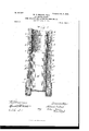
- Figure 1 is a sectional view of a device embodying my invention, showing the core-breaker out of contact with the core and the drill in position for drilling.
- Fig. 2 isasectional view of the same device, showing the core-breaker in operative engagement with and lifting the core.
- Fig. 3 is an elevation of a device embraced in my invention.
- Fig. 4 is an elevation of a longitudinally-ribbed coupling-sleeve embodied in my invention.
- Fig. 5 is a section on line 5 5 of Fig. 2.
- Fig. 6 is a view of one form of core-breakerembracedin'myinvention.
- Fig. 7 is a section on line 7 7 of Fig. 2.
- Fig. 8 is a view of a carrier-shell having apertures through which the core-breaker jaws operate.
- Adevice embodying myinvention embraces a tubular drill-rod A, a core-lifter shell B, havingserewthreaded engagement with the lower end of the drill-rod A, a coupling-sleeve C, having a sliding or telescopic engagement with the lower end of the core-lifting shell B, and a cutting-head D, attached at its upper end to said coiipling sleeve.
- the coupling -sleeve C is provided with external longitudinal ribs or grooves and is engaged with the shell 13 by means of a notched or grooved inwardly-projecting part or flange on the lower end of said shell, herein shown as formed by means of a separate ring H, connected by screw-threads with said shell.
- the said sleeve C has at its upper edge a stop-flange c, which by contact with the upper edge of the ring H prevents separation of the parts .and limits the downward movement of the drill-head with respect to the said shell.
- a sliding shell or cylinder E is located within said core-lifting shell B and engages at its lower end the couplingsleeve C, and a spiral spring F surrounds the upper part of said shell E and operates by endwise expansion to throw downwardly or outwardly the said shell and the connected coupling-sleeve and drill-head.
- Said spring is located between the upper part of the shell E and the part of the shell B which surrounds the same and is held or confined at its ends by contact with a shoulder on the drill-rod too at its upper end and a shoulder on the shell E at its lower end.
- the bearing-shoulder for the upper end of the spring is formed by the lower end of the drill-rod A, while that for its lower end is formed by a ring 8, which is secured by rivets to the said shell E.
- Serrated wedge-shaped gripping-jaws G are located within the shell B and engage an inclined or conical interior surface Z), which forms within the shell a conical recess larger at its upper than at its lower end.
- the inner or gripping faces of said jaws extend through openings 6 in the shellE.
- Said jaws are shown as having the form of blocks eonnccted by intermediate parts or webs, so as to form a ring, as shown in Fig. '7, said ring being cut or split at one point to enable it to expand and contract as the jaws are moved inwardly or outwardly.
- the core is indicated by M in the drawings.
- the tubular drill-rod A is provided at its lower end with an externallyscrewthreaded portion a of less diameter than the drill-rod and formingan external shoulder a.
- the inner part of the lower end of said drillrod is reamed out to form an annular recess to receive the upper end of the shell F, which is adapted to slide therein, the upper limit of said recess forming the shoulder Q
- the said drill-rod is also provided with an external spiral. clearance-groove a in a familiar manner.
- the core-lifter shell 13 has the same external diameter as the said drill-rod A and is also provided with a spiral clearance-groove continuous with that of the drill-rod when the said shell B is in place upon the drill-rod.
- the upper end of said shell B is provided on its inner surface with the screw-thread 1), adapted to be engaged by the screw-threaded end a of the drill-rod.
- the thickness of the shell B at the said part is equal to the depth of the said shoulder a, so that the outer surfaces of the said drill-rod and said shell B form a continuous cylindrical surface, and the spiral grooves of the said shell B are continuous with the similargrooves a a of the drillrod.
- the inner surface of the said shell B is enlarged above the conical part thereof to re ceive the spring F, which surrounds the upper part of the said shell below the lower end of the drill-rod.
- the lower end of said shell B is provided with a cylindric enlargement 12 in which the stop-flange c of the couplingsleeve fits and slides.
- the lower end of said core-lifting shell is provided with an interior screw-thread adapted to receive the externally-screw-threaded end of the notched ring H, which is, in effect, an extension of the corelifting shell.
- the said ring H is provided with inner longitudinal notches h, (shown on Fig. 5,) which engage the ribs on the couplingsleeve.
- the eore-bitD may be of any approved design, but as herein shown is a metal ring armed with diamond cutters at its lower edge, and is attached by a screw-thread to the coupling-sleeve O.
- the said sleeve has an interior diameter slightly greater than the core and is provided with external screwthreads at its lower end adapted to engage similar internal screw-threads in the upper end of the cutting-head. This manner of engagement with the cutting-head causes the upper end of the cutting-head to constitute an upwardly-facing shoulder d.
- the upper end of the said coupling-sleeve C is provided with an outwardly-extending flange 0, having an external diameter equal to the interior diameter of the core-lifting shell at the enlargement or recess 12
- the bore of said sleeve 0 is reamed out at its upper end to receive the lower end of the cylindrical carrier-shell E, hereinafter described.
- the said couplingsleeve is provided externally with longitudinal ribs 0, corresponding with the notches h of the ring H and adapted to slide therein. Said ribs and notches are provided to communicate the rotary motion of the drill-rod to the cutting-head.
- the sliding shell E rests upon the upper end of the said couplingsleeve, and the inner surfaces of the couplingsleeve and carrier-shell form one continuous cylindrical surface, and the length of the said carrier-shell is such that when the said coupling-sleeve C is at its lower point the carriershell resting thereon shall extend upwardly until the upper endthereof shall extendinto the enlargement in the end of the tubular drill-rod.
- the lower ends of the grippingjaws G are beveled inwardly,as shown in Figs.
- the operation of the device is as follows: When the apparatus constructed as described is set in operation, the thrust of the drill-rod A against the resistance of the rock causes the spring F to be compressed until upward movement of the drill-head is arrested by contact of its upper end with the ring 1-1. As shown in Fig. 1, owing to the taper of the surface I) and the beveled shape of the lower end of the core-gripping jaws G, as heretofore described, the jaws will be forced upward and outwardly to the position shown in said Fig. 1. In this position the core-breaker is entirely out of contact with the core and will so remain so long as operative pressure is maintained upon the cutting-head.
- said ring may be made of such diameter that the tension of the springs will either tend to close the jaws on the core or to hold them free therefrom, the spring in one case aiding the actuating-spring F and in the other case supplementing the eX- panding devices in throwing the jaws away from the core.
- the ring may, however, be made of an intermediate size, so that it will be made neutral, and both expansion and contraction in that case will be effected solely by the action of the said spring or by the upward thrust of the sliding shell.
- the connecting parts between the jaws serve merely as a means of holding them in place; but as the openings in the shell also perform this function the said connecting parts may be omitted and a series ofseparate jaws employed. It is also obvious that the spring F may be omitted, and the gravity of the cuttin g-head and connected parts may be utilized to ad vance the cuttin g-head in the withdrawal of the drillrod.
- the cuttinghead has an endwise or telescopic movement with respect to' the drill-rod or core-barrel and that the actuation of the core-gripping device is effected automatically and solely by such endwise-sliding or telescopic movement of the cutting-head.
- a distinctive feature is the endwisesliding or telescopic movement of the cuttin head as distinguished from a rotative or combined rotative and endwise movement of the cutting-head, such as is presented in the device illustrated in the said prior application hereinbefore referred to.
- MILAN C BULLOCK.
Landscapes
- Life Sciences & Earth Sciences (AREA)
- Engineering & Computer Science (AREA)
- Geology (AREA)
- Mining & Mineral Resources (AREA)
- Physics & Mathematics (AREA)
- Environmental & Geological Engineering (AREA)
- Fluid Mechanics (AREA)
- General Life Sciences & Earth Sciences (AREA)
- Geochemistry & Mineralogy (AREA)
- Earth Drilling (AREA)
Description
No. 643,082. Patented Feb, 6, I900. M. C. BULLOCK, Decd.
M. A. BULLOCK. Executrix. CURE BREAKER AND LIFTER FOB ROCK DRILLS.
(Application filed Sept. 22, IQQB.)
(No Model.) a sheets-sa a: l.
E CT/ I a/ .62,
E 6 Z g 3' lVw 6737 57" %Z@%QZ2ZZ0 N0. 643,082. Patented Feb. 6, I900. Mp0. BULLOCK, Decd. M. A. BULLOCK, Executrix. CURE BREAKER AND LIFTER FDR ROCK DRILLS.
3 Sheets-Sheet 2.
(Application filed Sept. 22, 1898.)
(No Model aw? E3 QZ 'InbemiW m0 CBuZZacZi No. 643,082. Patented Feb. 6, I900. m. c. BULLOCK, Decd. M. A. BULLDGK, Executrix.
GORE BREAKER AND LIFTER FOR BUCK DRILLS.
(Applicatiop filed Sept. 22, 1898.)
(No Model.)
I 3 Sheets-Sheat 3.
II/I/I n, 1W n 6 92. H 6 v. 7ZZ-766665 I L03 M w 4. %w z%w Jam max/M gMmgd 92255" much.
MILAN C. BULLOCK, OF CHICAGO, ILLINOIS; MARY A. BULLOCK, EXECUTRIX OF SAID MILAN C. BULLOCK, DECEASED, ASSIGNOR TO MARY ANN BUL- LOCK.
CORE BREAKER AND LIFTER FOR ROCK-DRILLS.
$PECIFICATION forming part Of Letters Patent NOu 643,082, dated February 6 1900.
Application filed September 22, 1898- Serial No. 691,604. (No model.)
To all whom, it may concern:
Be it known that I, MILAN O. BULLOCK, of Chicago, in the county of Cook and State of Illinois, have invented certain new and use ful Improvements in Core Breakers and Lifters for Rock-Drills; and I do hereby declare that the following is a full, clear, and exact description thereof, reference being had to the accompanying drawings, and to the letters of reference marked thereon, which form a part of this specification.
This invention relates to an improved corebreaking and core-lifting device for drilling apparatus of that kind having rotary tubular bits or cutters, such as are commonly known as diamond drills. V
In a separate application for Letters Patent filed by me on the 22d day of September, 1898, Serial No. 691,603, I have shown a drilling apparatus having a drill-rod or corebarrel, a cutting-head which is movable with respect to the drill-rod or core-barrel, and core gripping devices which are actuated automatically through the movement of the cutting-head with respect to the drill-rod or core-barrel.
The present invention embraces the general principles of construction illustrated in said prior application and constitutes a species of the generic invention therein set forth. In the mechanism specifically illustrated in the prior application the core-gi'ippin g device is actuated through a rotative movement of the cutting-head with respect to the drill-rod or core-barrel. In the present application another form of core-actuating means is employed, wherein the cutting-head has an endwise-sliding or telescopic movement with respect to the drillrod or core-barrel, and the actuation of the core-gripping device is effected solely through such telescopic movement, the parts being so arranged that when the drill-rod is thrust forward in cutting or drilling the cutting-head will be moved backwardly, and thereby relieve the gripping de vice from contact with the core, and when the drill-rod is withdrawn the cutting-head will be advanced with respect thereto and close the gripping device upon the core.
The invention consists in the matters hereinafter described, and pointed out in the appended claims.
As shown in the drawings, Figure 1 is a sectional view of a device embodying my invention, showing the core-breaker out of contact with the core and the drill in position for drilling. Fig. 2 isasectional view of the same device, showing the core-breaker in operative engagement with and lifting the core. Fig. 3 is an elevation of a device embraced in my invention. Fig. 4 is an elevation of a longitudinally-ribbed coupling-sleeve embodied in my invention. Fig. 5 is a section on line 5 5 of Fig. 2. Fig. 6 is a view of one form of core-breakerembracedin'myinvention. Fig. 7 is a section on line 7 7 of Fig. 2. Fig. 8 is a view of a carrier-shell having apertures through which the core-breaker jaws operate.
Adevice embodying myinvention,asshown in the said drawings, embraces a tubular drill-rod A, a core-lifter shell B, havingserewthreaded engagement with the lower end of the drill-rod A, a coupling-sleeve C, having a sliding or telescopic engagement with the lower end of the core-lifting shell B, and a cutting-head D, attached at its upper end to said coiipling sleeve. The coupling -sleeve C is provided with external longitudinal ribs or grooves and is engaged with the shell 13 by means of a notched or grooved inwardly-projecting part or flange on the lower end of said shell, herein shown as formed by means of a separate ring H, connected by screw-threads with said shell. The said sleeve C has at its upper edge a stop-flange c, which by contact with the upper edge of the ring H prevents separation of the parts .and limits the downward movement of the drill-head with respect to the said shell. A sliding shell or cylinder E is located within said core-lifting shell B and engages at its lower end the couplingsleeve C, and a spiral spring F surrounds the upper part of said shell E and operates by endwise expansion to throw downwardly or outwardly the said shell and the connected coupling-sleeve and drill-head. Said spring is located between the upper part of the shell E and the part of the shell B which surrounds the same and is held or confined at its ends by contact with a shoulder on the drill-rod too at its upper end and a shoulder on the shell E at its lower end. Conveniently the bearing-shoulder for the upper end of the spring is formed by the lower end of the drill-rod A, while that for its lower end is formed by a ring 8, which is secured by rivets to the said shell E. Serrated wedge-shaped gripping-jaws G are located within the shell B and engage an inclined or conical interior surface Z), which forms within the shell a conical recess larger at its upper than at its lower end. The inner or gripping faces of said jaws extend through openings 6 in the shellE. Said jaws are shown as having the form of blocks eonnccted by intermediate parts or webs, so as to form a ring, as shown in Fig. '7, said ring being cut or split at one point to enable it to expand and contract as the jaws are moved inwardly or outwardly. The core is indicated by M in the drawings.
Referring to the details of construction illustrated, the tubular drill-rod A is provided at its lower end with an externallyscrewthreaded portion a of less diameter than the drill-rod and formingan external shoulder a. The inner part of the lower end of said drillrod is reamed out to form an annular recess to receive the upper end of the shell F, which is adapted to slide therein, the upper limit of said recess forming the shoulder Q The said drill-rod is also provided with an external spiral. clearance-groove a in a familiar manner. The core-lifter shell 13 has the same external diameter as the said drill-rod A and is also provided with a spiral clearance-groove continuous with that of the drill-rod when the said shell B is in place upon the drill-rod. The upper end of said shell B is provided on its inner surface with the screw-thread 1), adapted to be engaged by the screw-threaded end a of the drill-rod. The thickness of the shell B at the said part is equal to the depth of the said shoulder a, so that the outer surfaces of the said drill-rod and said shell B form a continuous cylindrical surface, and the spiral grooves of the said shell B are continuous with the similargrooves a a of the drillrod. The inner surface of the said shell B is enlarged above the conical part thereof to re ceive the spring F, which surrounds the upper part of the said shell below the lower end of the drill-rod. The lower end of said shell B is provided with a cylindric enlargement 12 in which the stop-flange c of the couplingsleeve fits and slides. The lower end of said core-lifting shell is provided with an interior screw-thread adapted to receive the externally-screw-threaded end of the notched ring H, which is, in effect, an extension of the corelifting shell. The said ring H is provided with inner longitudinal notches h, (shown on Fig. 5,) which engage the ribs on the couplingsleeve.
The eore-bitD may be of any approved design, but as herein shown is a metal ring armed with diamond cutters at its lower edge, and is attached by a screw-thread to the coupling-sleeve O. The said sleeve has an interior diameter slightly greater than the core and is provided with external screwthreads at its lower end adapted to engage similar internal screw-threads in the upper end of the cutting-head. This manner of engagement with the cutting-head causes the upper end of the cutting-head to constitute an upwardly-facing shoulder d. The upper end of the said coupling-sleeve C is provided with an outwardly-extending flange 0, having an external diameter equal to the interior diameter of the core-lifting shell at the enlargement or recess 12 The bore of said sleeve 0 is reamed out at its upper end to receive the lower end of the cylindrical carrier-shell E, hereinafter described. The said couplingsleeve is provided externally with longitudinal ribs 0, corresponding with the notches h of the ring H and adapted to slide therein. Said ribs and notches are provided to communicate the rotary motion of the drill-rod to the cutting-head. The sliding shell E rests upon the upper end of the said couplingsleeve, and the inner surfaces of the couplingsleeve and carrier-shell form one continuous cylindrical surface, and the length of the said carrier-shell is such that when the said coupling-sleeve C is at its lower point the carriershell resting thereon shall extend upwardly until the upper endthereof shall extendinto the enlargement in the end of the tubular drill-rod. The lower ends of the grippingjaws G are beveled inwardly,as shown in Figs. 1 and 2, and are adapted to engage the edges of the sliding shell at the lower parts of the aperture 0 so thatwhen the said carriershell is forced upwardly the lower wall of the aperture will press outwardly on the jaws and carry them out of contact with the core and into the upper part of the conical recess.
The operation of the device is as follows: When the apparatus constructed as described is set in operation, the thrust of the drill-rod A against the resistance of the rock causes the spring F to be compressed until upward movement of the drill-head is arrested by contact of its upper end with the ring 1-1. As shown in Fig. 1, owing to the taper of the surface I) and the beveled shape of the lower end of the core-gripping jaws G, as heretofore described, the jaws will be forced upward and outwardly to the position shown in said Fig. 1. In this position the core-breaker is entirely out of contact with the core and will so remain so long as operative pressure is maintained upon the cutting-head. When the drill-rod is raised, the spring F immediately expands and the carrying-sleeve E and all parts engaged therewith are forced downwardly to the position shown in Figs. 2 and 3. This movement is of course aided by the weight of the drill-head. The inclined surface I) acting on the gripping-jaws G forces the said jaws inwardly into contact with the core, as shown in said Fig. 1. It is obvious that in this position the greater the upward will grip the core.
When the gripping-jaws and the metal parts connecting them are adapted to constitute a spring-ring, as shown, said ring may be made of such diameter that the tension of the springs will either tend to close the jaws on the core or to hold them free therefrom, the spring in one case aiding the actuating-spring F and in the other case supplementing the eX- panding devices in throwing the jaws away from the core. The ring may, however, be made of an intermediate size, so that it will be made neutral, and both expansion and contraction in that case will be effected solely by the action of the said spring or by the upward thrust of the sliding shell. Obviously the connecting parts between the jaws serve merely as a means of holding them in place; but as the openings in the shell also perform this function the said connecting parts may be omitted and a series ofseparate jaws employed. It is also obvious that the spring F may be omitted, and the gravity of the cuttin g-head and connected parts may be utilized to ad vance the cuttin g-head in the withdrawal of the drillrod.
From the above description of the construction and operation of the device illustrated it will be clear that in this invention the cuttinghead has an endwise or telescopic movement with respect to' the drill-rod or core-barrel and that the actuation of the core-gripping device is effected automatically and solely by such endwise-sliding or telescopic movement of the cutting-head. In the apparatus herein shown, therefore, a distinctive feature is the endwisesliding or telescopic movement of the cuttin head as distinguished from a rotative or combined rotative and endwise movement of the cutting-head, such as is presented in the device illustrated in the said prior application hereinbefore referred to.
I claim as my in vention- 1. The combination with a dr,illr0d of an annular cutting-head which slides endwise with respect to the drill-rod, an expansible core-gripper and means actuated through the endwise movement of the cutting-head acting to hold the core-gripper extended during the operation of drilling.
2. The combination with a drill-rod of an annular cutting-head which is movable endwise with respect to the drill-rod, an expansible core-gripper comprising endwise and radially movable grippingjaws and means actuating said jaws, comprising an inclined surface of the interior of the drill-rod, and
connecting means between the cutting-head and said jaws by which the latter are moved with respect to the inclined surface in the endwise movement of said cutting-head.
The combination with a drill-rod of an annular cutting-head which is movable endwise with respect to the drill-rod, a spring applied to extend the cutting-head, an expansiblc core-gripper and actuating means for the core-gripper embracing operative connections with the cutting-head, whereby the coregripper is contracted when the cutting-head is thrown outwardly by said spring, and extended when said cutting-head is forced inward by pressure against the rock in drilling. at. The combination with a drill-rod of an annular cutting-head which is movable endwise with respect to the drill-rod, a spring applied to extend the cutting-head, an expansible core-gripper and means for actuating said core-gripper, embracing an inclined surface on the drill-rod and a connection between the moving parts of the gripper and the cuttinghead by which the said moving parts are ac tuated through the end wise movement of the cutting-head.
5. The combination with a drill-rod provided with an inclined interior surface, of an annular cutting-head which is movable endwise with respect to the drill-rod, an expansi ble core-gripper, embracing jaws which en gage and slide endwise upon said inclined surface of the core-barrel and an operative connection between said cutting-head and said jaws, acting to move the said jaws within the drill-rod when the cutting-head is moved with respect to said drill-rod.
6. The combination with a drill-rod provided with an interior inclined surface, of an annular cutting-head which is movable endwise with respect to said drill-rod, an expansible core-gripper, embracing jaws which engage said inclined surface of the drill-rod, connecting means between the cutting-head and jaws acting to move said jaws endwise with the cutting-head and a spring applied between the cutting-head and the drill-rod to extend the cutting-head.
7. The combination with a drill-rod provided with an interior inclined surface, of an annular cutting-head which is movable endwise with respect to the drill-rod, acore-gripper, embracing jaws which engage and slide endwise upon said inclined surface, and a sliding sleeve connecting said jaws with the said cutting-head.
8. The combination with a drill-rod provided with an interior inclined surface, of an annular cutting-head which is movable endwise with respect to the drill-rod, a core-gripper, embracing jaws which engage and slide endwise upon said inclined surface, a sliding sleeve connecting said jaws with the said outting-head, and an actuating-spring applied between the said sleeve and the drill-rod.
9. The combination with the drill-rod of an annular cutting-head provided with a longitudinally-grooved sleeve which has sliding engagement with a notched flange on the drillrod, a core-gripperand actuating means for operating the core-gripper through the endwise movement of the cutting-head with respect to the drill-rod.
10. The combination of a tubular drill-rod provided with an interior tapered surface and with a notched flange at its lower end, of an IIO annular cutting-head provided with a longitudinally-grooved sleeve which has sliding engagement with said notched flange, a grip-- ping device, embracing jaws which slide upon said inclined surface, and connecting means between the jaws and said cutting-head for actuating the former from the latter.
11. The combination of a tubular drillingrod provided with an interior tapered surface, an annular cutting-head which has endwisesliding engagement with the drill-rod, a sliding sleeve within the drill-rod engaging with said cutting-head and provided with openings for gripper-jaws, and gripper-jaws engaging with said openings and bearing against th inclined surface of the drill-rod.
12. The combination with a drill-rod provided with an interior conical surface, an annular cutting-head having endwise-sliding engagement with the drill-rod, a sliding sleeve engaging with the cutting-head and provided with an opening for gripping-jaws, grippingjaws which engage said openings and bear against the said inclined surface, and a coiled spring surrounding said sleeve and bearing at one end against a shoulder on the drill-rod and at its opposite end against a shoulder on said sleeve.
13. The combination with a drill-rod provided with an interior tapered surface, a drillhead having endwise-sliding engagement with said drill-rod, a sliding sleeve connected with said drill-head and provided with openings to engage clamping-jaws, clamping-jaws to bear against the said inclined surface and engage said openings, said clamping-jaws being provided with inclined surfaces adapted for engagement with said sliding sleeve and acting to throw outwardly the clamping-jaws when the cutting-head and sleeve are thrust inwardly.
In testimony that I claim the foregoing as my invention I affix my signature, in presence of two witnesses, this 2d day of September, A. D. 1898.
MILAN C. BULLOCK.
Witnesses:
CHARLES S. BARTHOLF, R. CUTHBERT VIVIAN.
Priority Applications (1)
| Application Number | Priority Date | Filing Date | Title |
|---|---|---|---|
| US69160498A US643082A (en) | 1898-09-22 | 1898-09-22 | Core breaker and lifter for rock-drills. |
Applications Claiming Priority (1)
| Application Number | Priority Date | Filing Date | Title |
|---|---|---|---|
| US69160498A US643082A (en) | 1898-09-22 | 1898-09-22 | Core breaker and lifter for rock-drills. |
Publications (1)
| Publication Number | Publication Date |
|---|---|
| US643082A true US643082A (en) | 1900-02-06 |
Family
ID=2711665
Family Applications (1)
| Application Number | Title | Priority Date | Filing Date |
|---|---|---|---|
| US69160498A Expired - Lifetime US643082A (en) | 1898-09-22 | 1898-09-22 | Core breaker and lifter for rock-drills. |
Country Status (1)
| Country | Link |
|---|---|
| US (1) | US643082A (en) |
Cited By (7)
| Publication number | Priority date | Publication date | Assignee | Title |
|---|---|---|---|---|
| US2422955A (en) * | 1943-08-16 | 1947-06-24 | Duffield Charles Francis | Core recovering device |
| US2503561A (en) * | 1945-11-19 | 1950-04-11 | Longyear E J Co | Core drill |
| US2698737A (en) * | 1953-02-24 | 1955-01-04 | Charles A Dean | Core drill |
| US2850265A (en) * | 1956-02-08 | 1958-09-02 | Ellery M Cruthers | Core extractor for core drill |
| US2876996A (en) * | 1955-05-05 | 1959-03-10 | Jersey Prod Res Co | Core barrel |
| US3349857A (en) * | 1965-07-16 | 1967-10-31 | Exxon Production Research Co | Coring apparatus |
| US5031708A (en) * | 1990-04-20 | 1991-07-16 | Longyear Company | Cockable corebreaker apparatus |
-
1898
- 1898-09-22 US US69160498A patent/US643082A/en not_active Expired - Lifetime
Cited By (7)
| Publication number | Priority date | Publication date | Assignee | Title |
|---|---|---|---|---|
| US2422955A (en) * | 1943-08-16 | 1947-06-24 | Duffield Charles Francis | Core recovering device |
| US2503561A (en) * | 1945-11-19 | 1950-04-11 | Longyear E J Co | Core drill |
| US2698737A (en) * | 1953-02-24 | 1955-01-04 | Charles A Dean | Core drill |
| US2876996A (en) * | 1955-05-05 | 1959-03-10 | Jersey Prod Res Co | Core barrel |
| US2850265A (en) * | 1956-02-08 | 1958-09-02 | Ellery M Cruthers | Core extractor for core drill |
| US3349857A (en) * | 1965-07-16 | 1967-10-31 | Exxon Production Research Co | Coring apparatus |
| US5031708A (en) * | 1990-04-20 | 1991-07-16 | Longyear Company | Cockable corebreaker apparatus |
Similar Documents
| Publication | Publication Date | Title |
|---|---|---|
| US465103A (en) | Combined drill | |
| US2132061A (en) | Quick action whip stock | |
| US1112349A (en) | Drill or the like and socket therefor. | |
| US643082A (en) | Core breaker and lifter for rock-drills. | |
| US1653547A (en) | Spear for oil-well casings or tubing | |
| US648920A (en) | Core breaker and lifter for rock-drills. | |
| US1066000A (en) | Tubing-catcher. | |
| US776523A (en) | Pipe-grab. | |
| US473910A (en) | Art of rock-core drilling | |
| US1689702A (en) | Fishing tool | |
| US1899469A (en) | Drill pipe joint | |
| US473909A (en) | Rock-drilling apparatus | |
| US529781A (en) | Per anton ceaelius | |
| US261841A (en) | Tubular rock-drill | |
| US179497A (en) | Improvement | |
| US872940A (en) | Tube-extractor for wells. | |
| US862381A (en) | Hydraulic drill and reamer. | |
| US672814A (en) | Drill-casing extractor. | |
| US665711A (en) | Rock-drill. | |
| US1762621A (en) | Spear | |
| US1476218A (en) | Rope grip for well-drilling apparatus | |
| US473907A (en) | Milan c | |
| US434860A (en) | Device for removing casing-tubes in rock and earth drilling | |
| US548607A (en) | Rock-core drill | |
| US2355263A (en) | Drilling unit for jigs or the like |