US6418626B1 - Pruning shears with a lock device - Google Patents
Pruning shears with a lock device Download PDFInfo
- Publication number
- US6418626B1 US6418626B1 US09/699,621 US69962100A US6418626B1 US 6418626 B1 US6418626 B1 US 6418626B1 US 69962100 A US69962100 A US 69962100A US 6418626 B1 US6418626 B1 US 6418626B1
- Authority
- US
- United States
- Prior art keywords
- knob
- latch post
- bodies
- pruning shears
- pivot
- Prior art date
- Legal status (The legal status is an assumption and is not a legal conclusion. Google has not performed a legal analysis and makes no representation as to the accuracy of the status listed.)
- Expired - Fee Related
Links
- 238000013138 pruning Methods 0.000 title claims abstract description 26
- 230000000694 effects Effects 0.000 abstract description 2
- 244000141353 Prunus domestica Species 0.000 description 1
- 230000000670 limiting effect Effects 0.000 description 1
Images


Classifications
-
- A—HUMAN NECESSITIES
- A01—AGRICULTURE; FORESTRY; ANIMAL HUSBANDRY; HUNTING; TRAPPING; FISHING
- A01G—HORTICULTURE; CULTIVATION OF VEGETABLES, FLOWERS, RICE, FRUIT, VINES, HOPS OR SEAWEED; FORESTRY; WATERING
- A01G3/00—Cutting implements specially adapted for horticultural purposes; Delimbing standing trees
- A01G3/02—Secateurs; Flower or fruit shears
-
- B—PERFORMING OPERATIONS; TRANSPORTING
- B26—HAND CUTTING TOOLS; CUTTING; SEVERING
- B26B—HAND-HELD CUTTING TOOLS NOT OTHERWISE PROVIDED FOR
- B26B13/00—Hand shears; Scissors
- B26B13/12—Hand shears; Scissors characterised by the shape of the handles
- B26B13/14—Hand shears; Scissors characterised by the shape of the handles without gripping bows in the handle
- B26B13/16—Hand shears; Scissors characterised by the shape of the handles without gripping bows in the handle spring loaded, e.g. with provision for locking the blades or the handles
Definitions
- the present invention relates to a pair of pruning shears, and more particularly to a pair of pruning shears having a lock device to securely hold the shears in a pushed position.
- a pair of conventional pruning shears in accordance with the prior art comprises two bodies ( 30 , 32 ) pivotally mounted together with a pivot.
- Each body ( 30 , 32 ) has a cutting end ( 302 , 322 ) formed on one end thereof and a handle ( 304 , 324 ) on another end.
- a spring ( 34 ) is connected between the handles ( 304 , 324 ) of the bodies ( 30 , 32 ) to provide a biasing force to push the handles ( 304 , 324 ) far away from each other. Therefore, the cutting ends ( 302 , 322 ) of the bodies ( 30 , 32 ) will keep in an open condition by the biasing force of the spring ( 34 ).
- a user especially a child, is easily cut by the open cutting ends ( 302 , 322 ) of the bodies ( 30 , 32 ) when he or she holds the pruning shears in play. Consequently, a lock device is always disposed between the bodies ( 30 , 32 ) to keep the pruning shears in a closed condition when the shears are not in use.
- the conventional lock device comprises a block ( 36 ) slidably mounted on the handle ( 304 ) of one of the bodies ( 30 ) and a recess ( 326 ) defined in the cutting end ( 322 ) of the other one of the bodies ( 32 ).
- the recess ( 326 ) will face the block ( 36 ).
- the bodies ( 30 , 32 ) will be locked as the block ( 36 ) is pushed to slide along the handle ( 304 ) and engage with the recess ( 326 ).
- the pruning shears can be held in the closed condition so as to avoid a person being cut by the cutting ends ( 302 , 322 ).
- the engagement between the block ( 36 ) and recess ( 306 ) is not enough.
- the present invention tends to provide a pair of pruning shears with an improved lock device to mitigate or obviate the aforementioned problems.
- the main objective of the invention is to provide a pair of pruning shears with a lock device to securely hold the shears in a closed position.
- the pruning shears comprises two bodies pivotally mounted together with a pivot, a spring connected between the bodies and a lock device arranged near the pivot.
- the lock device comprises a step hole, a locking hole, a latch post, a biasing member and a knob.
- the step hole is defined in one of the bodies near the pivot, and the locking hole is defined in the other body to align with the step hole when the bodies are pushed together.
- the latch post is moveably mounted in the step hole.
- the biasing member is received in the step hole to support the latch post.
- the knob is rotatably mounted on the body with the step hole.
- the knob has a bottom abutting the latch post and a cavity defined in the bottom of the knob to face the latch post.
- the latch post can be pushed to engage with the locking hole by the bottom of the knob. This can provide a securely positioning effect to the latch post to avoid the post escaping from the locking hole as the pruning shears bump with another object, fall, etc.
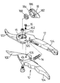
- FIG. 1 is an exploded perspective view of a pair of pruning shears with a lock device in accordance with the invention
- FIG. 2 is a front plan view in partial section of the pair of pruning shears in FIG. 1 showing the bodies being kept in a closed condition by the lock device;
- FIG. 3 is a partial side plan view in partial section of the lock device in FIG. 2 showing the bodies being locked;
- FIG. 4 is a front plan view in partial section of the pair of pruning shears in FIG. 1 showing the lock device being released;
- FIG. 5 is a partial side plan view in partial section of the lock device in FIG. 4;
- FIG. 6 is a front plan view in partial section of a pair of pruning shears with a conventional lock device in accordance with the prior art.
- a pair of pruning shears in accordance with the present invention comprises two bodies ( 10 , 12 ) pivotally mounted together with a pivot (not numbered), a spring ( 14 ) and a lock device arranged near the pivot.
- Each body ( 10 , 12 ) has a cutting end ( 102 , 122 ) formed on one end thereof and a handle ( 104 , 124 ) on another end.
- the spring ( 14 ) is connected between the handles ( 104 , 124 ) of the bodies ( 10 , 12 ) to provide a biasing force to keep distal ends of the handles ( 104 , 124 ) far away from each other.
- the lock device comprises a step hole ( 126 ), a locking hole ( 106 ), a latch post ( 16 ), a biasing member ( 162 ) and a knob ( 18 ).
- the step hole ( 126 ) is defined in one of the bodies, in this embodiment ( 12 ), near the pivot.
- the locking hole ( 106 ) is defined in the other one of the bodies ( 14 ) to align with the step hole ( 126 ) when the bodies ( 10 , 12 ) are pushed to close.
- the latch post ( 16 ) is moveably mounted in the step hole ( 126 ).
- the biasing member ( 162 ) is received in the step hole ( 126 ) to support the latch post ( 16 ).
- the knob ( 18 ) is rotatably mounted on the body ( 12 ) via the step hole ( 126 ).
- the knob ( 18 ) has a bottom which abuts the latch post ( 16 ), and a cavity ( 182 ) defined in the bottom of the knob ( 18 ) faces the latch post ( 16 ).
- a recess ( 186 ) is defined in the bottom of the knob ( 18 ).
- An annular collar ( 188 ) is received in the recess to hold the pivot for connecting the two bodies ( 10 , 12 ). Consequently, the knob ( 18 ) will not diametrically vibrate relative to the body ( 12 ) due to the engagement between the collar ( 188 ) and the pivot.
- a chamber ( 15 ) is defined in the body ( 12 ) to rotatably receive the knob ( 18 ), and the step hole ( 126 ) is defined in a periphery defining the chamber ( 15 ).
- Two flanges ( 184 ) separately and laterally extend from a bottom of the knob ( 18 ).
- the flanges ( 184 ) are preferably at opposite sides of the diameter of the knob ( 18 ).
- Each flange ( 184 ) has a length in 90° radian.
- Two extensions ( 152 ) separately and laterally extend into the chamber ( 15 ) at opposite ends of the diameter of the chamber ( 15 ).
- each extension ( 152 ) is apart from the face of the chamber ( 15 ), and a channel is defined between each extension ( 152 ) and a respective face of the chamber ( 15 ). To fit with the flange ( 184 ) on the knob ( 18 ), each extension ( 152 ) has a length in 90° radian.
- the distal ends of the bodies ( 10 , 12 ) are firstly pushed close to each other whereby the locking hole ( 106 ) aligns with the step hole ( 126 ). Then the knob ( 18 ) is rotated to an angle that the portion of bottom of the knob ( 18 ) without the cavity ( 182 ) faces and abuts the latch post ( 16 ). The latch post ( 16 ) is then pushed into and engages with the locking hole ( 106 ) and the biasing member ( 162 ) is pressed. The bodies ( 10 , 12 ) are locked by the engagement of the latch post ( 16 ) and locking hole ( 106 ). The pruning shears can be held in a closed condition by the lock device.
- the knob ( 18 ) can provide a good limiting effect to the latch post ( 16 ).
- the latch post ( 16 ) will not escape from the locking hole ( 106 ) when the pruning shears bumps with another object or drops to the ground. This can provide good safety to a person, even when he or she holds the pruning shears in play.
Landscapes
- Life Sciences & Earth Sciences (AREA)
- Forests & Forestry (AREA)
- Biodiversity & Conservation Biology (AREA)
- Ecology (AREA)
- Environmental Sciences (AREA)
- Engineering & Computer Science (AREA)
- Mechanical Engineering (AREA)
- Scissors And Nippers (AREA)
Abstract
A pair of pruning shears has two bodies pivotally mounted together with a pivot, a spring connected between the bodies, and a lock device arranged near the pivot. The lock device comprises a step hole defined in one of the bodies near the pivot, a locking hole defined in the other body, a latch post moveably mounted in the step hole, a biasing member to support the latch post, and a knob. The knob is rotatably mounted on the body with the step hole. The knob has a bottom abutting the latch post and a cavity defined in the bottom. When the bodies are pushed toward to each other, the step hole will align with the locking hole. The latch post can be pushed to engage with the locking hole by the bottom of the knob. This can provide a secure positioning effect to the latch post. The latch post will not escape from the locking hole when the pruning shears bump with another object.
Description
1. Field of the Invention
The present invention relates to a pair of pruning shears, and more particularly to a pair of pruning shears having a lock device to securely hold the shears in a pushed position.
2. Description of Related Art
With reference to FIG. 6, a pair of conventional pruning shears in accordance with the prior art comprises two bodies (30,32) pivotally mounted together with a pivot. Each body (30,32) has a cutting end (302,322) formed on one end thereof and a handle (304,324) on another end. A spring (34) is connected between the handles (304,324) of the bodies (30,32) to provide a biasing force to push the handles (304,324) far away from each other. Therefore, the cutting ends (302,322) of the bodies (30,32) will keep in an open condition by the biasing force of the spring (34). However, a user, especially a child, is easily cut by the open cutting ends (302,322) of the bodies (30,32) when he or she holds the pruning shears in play. Consequently, a lock device is always disposed between the bodies (30,32) to keep the pruning shears in a closed condition when the shears are not in use.
The conventional lock device comprises a block (36) slidably mounted on the handle (304) of one of the bodies (30) and a recess (326) defined in the cutting end (322) of the other one of the bodies (32). When the bodies (30,32) are pushed toward to each other, the recess (326) will face the block (36). The bodies (30,32) will be locked as the block (36) is pushed to slide along the handle (304) and engage with the recess (326). With such a lock device, the pruning shears can be held in the closed condition so as to avoid a person being cut by the cutting ends (302,322).
However, because no positioning structure is applied to the block (36), the engagement between the block (36) and recess (306) is not enough. In particular, there is always a gap defined between the block (36) and the body (30) to reduce the friction therebetween and this will further decrease the engaging strength between the block (36) and the recess (326) furthermore, the block (36) easily escapes from the recess (326) as the pruning shears bumps with another object or drops to the ground.
To overcome the shortcomings, the present invention tends to provide a pair of pruning shears with an improved lock device to mitigate or obviate the aforementioned problems.
The main objective of the invention is to provide a pair of pruning shears with a lock device to securely hold the shears in a closed position. The pruning shears comprises two bodies pivotally mounted together with a pivot, a spring connected between the bodies and a lock device arranged near the pivot. The lock device comprises a step hole, a locking hole, a latch post, a biasing member and a knob. The step hole is defined in one of the bodies near the pivot, and the locking hole is defined in the other body to align with the step hole when the bodies are pushed together. The latch post is moveably mounted in the step hole. The biasing member is received in the step hole to support the latch post. The knob is rotatably mounted on the body with the step hole. The knob has a bottom abutting the latch post and a cavity defined in the bottom of the knob to face the latch post. The latch post can be pushed to engage with the locking hole by the bottom of the knob. This can provide a securely positioning effect to the latch post to avoid the post escaping from the locking hole as the pruning shears bump with another object, fall, etc.
Other objects, advantages and novel features of the invention will become more apparent from the following detailed description when taken in conjunction with the accompanying drawings.
FIG. 1 is an exploded perspective view of a pair of pruning shears with a lock device in accordance with the invention;
FIG. 2 is a front plan view in partial section of the pair of pruning shears in FIG. 1 showing the bodies being kept in a closed condition by the lock device;
FIG. 3 is a partial side plan view in partial section of the lock device in FIG. 2 showing the bodies being locked;
FIG. 4 is a front plan view in partial section of the pair of pruning shears in FIG. 1 showing the lock device being released;
FIG. 5 is a partial side plan view in partial section of the lock device in FIG. 4; and
FIG. 6 is a front plan view in partial section of a pair of pruning shears with a conventional lock device in accordance with the prior art.
With reference to FIG. 1, a pair of pruning shears in accordance with the present invention comprises two bodies (10,12) pivotally mounted together with a pivot (not numbered), a spring (14) and a lock device arranged near the pivot. Each body (10,12) has a cutting end (102,122) formed on one end thereof and a handle (104,124) on another end. The spring (14) is connected between the handles (104,124) of the bodies (10,12) to provide a biasing force to keep distal ends of the handles (104, 124) far away from each other.
The lock device comprises a step hole (126), a locking hole (106), a latch post (16), a biasing member (162) and a knob (18). The step hole (126) is defined in one of the bodies, in this embodiment (12), near the pivot. The locking hole (106) is defined in the other one of the bodies (14) to align with the step hole (126) when the bodies (10,12) are pushed to close. The latch post (16) is moveably mounted in the step hole (126). The biasing member (162) is received in the step hole (126) to support the latch post (16). The knob (18) is rotatably mounted on the body (12) via the step hole (126). The knob (18) has a bottom which abuts the latch post (16), and a cavity (182) defined in the bottom of the knob (18) faces the latch post (16). A recess (186) is defined in the bottom of the knob (18). An annular collar (188) is received in the recess to hold the pivot for connecting the two bodies (10,12). Consequently, the knob (18) will not diametrically vibrate relative to the body (12) due to the engagement between the collar (188) and the pivot.
A chamber (15) is defined in the body (12) to rotatably receive the knob (18), and the step hole (126) is defined in a periphery defining the chamber (15). Two flanges (184) separately and laterally extend from a bottom of the knob (18). The flanges (184) are preferably at opposite sides of the diameter of the knob (18). Each flange (184) has a length in 90° radian. Two extensions (152) separately and laterally extend into the chamber (15) at opposite ends of the diameter of the chamber (15). Each extension (152) is apart from the face of the chamber (15), and a channel is defined between each extension (152) and a respective face of the chamber (15). To fit with the flange (184) on the knob (18), each extension (152) has a length in 90° radian.
By such an arrangement, when each flange (184) faces a gap defined between the adjacent extensions (152), the knob (18) can be put into the chamber (15). Then the knob (18) is rotated such that each flange (184) is moved into the channel and abuts a bottom side of a respective one of the extensions (152). Consequently, the knob (18) can be rotatably held in the chamber (15) by the engagement between each flange (184) and extension (152). In locking the pruning shears, with reference to FIGS. 2 and 3, the distal ends of the bodies (10,12) are firstly pushed close to each other whereby the locking hole (106) aligns with the step hole (126). Then the knob (18) is rotated to an angle that the portion of bottom of the knob (18) without the cavity (182) faces and abuts the latch post (16). The latch post (16) is then pushed into and engages with the locking hole (106) and the biasing member (162) is pressed. The bodies (10,12) are locked by the engagement of the latch post (16) and locking hole (106). The pruning shears can be held in a closed condition by the lock device. With such a lock device, the knob (18) can provide a good limiting effect to the latch post (16). The latch post (16) will not escape from the locking hole (106) when the pruning shears bumps with another object or drops to the ground. This can provide good safety to a person, even when he or she holds the pruning shears in play.
With reference to FIGS. 4 and 5, when the knob (18) is rotated to an angle that the cavity (182) faces the latch post (16), the pushing force provided by the knob (18) to the latch post (16) is eliminated, and the biasing member (162) pushes the latch post (16) out from the locking hole (106), whereby the engagement between the latch post (16) and locking hole (106) is released. The bodies (10,12) can rotate relative to each other, and the pair of pruning shears can be used to cut and prune trees or flowers.
Even though numerous characteristics and advantages of the present invention have been set forth in the foregoing description, together with details of the structure and function of the invention, the disclosure is illustrative only, and changes may be made in detail, especially in matters of shape, size, and arrangement of parts within the principles of the invention to the full extent indicated by the broad general meaning of the terms in which the appended claims are expressed.
Claims (2)
1. A pair of pruning shears with a lock device comprising:
a first body and a second body pivotally mounted together with a pivot, the first body and the second body each having a cutting end formed on one end thereof and a handle formed on the other end;
a spring connected between the first and the second handles of each of the bodies;
a stepped hole defined in the first body near the pivot;
a latch post moveably mounted in the stepped hole;
a biasing member received in the stepped hole to support the latch post;
a locking hole defined in the second body to align with the stepped hole when the bodies are pushed to close so as to engage with the latch post;
a knob rotatably mounted on the first body and having a bottom abutting the latch post; and
a cavity defined in the bottom of the knob to face the latch post, wherein a chamber is defined in the first body to rotatably receive the knob;
the stepped hole is defined in a face defining the chamber;
at least one flange radially extends from the bottom of the knob;
an extension laterally extends into the chamber and apart from the face of the chamber to engage with each of the at least one flange of the knob; and
each at least one flange has a length in 90° radian, and the extension has a length in 90° radian,
thereby the knob can be rotatably held in the chamber by means of engagement between each flange and extension.
2. The pruning shears as claimed in claim 1 , wherein a recess is defined in the bottom of the knob; and
an annular collar is received in the recess to hold the pivot by which the two bodies are pivotally connected.
Priority Applications (1)
| Application Number | Priority Date | Filing Date | Title |
|---|---|---|---|
| US09/699,621 US6418626B1 (en) | 2000-10-30 | 2000-10-30 | Pruning shears with a lock device |
Applications Claiming Priority (1)
| Application Number | Priority Date | Filing Date | Title |
|---|---|---|---|
| US09/699,621 US6418626B1 (en) | 2000-10-30 | 2000-10-30 | Pruning shears with a lock device |
Publications (1)
| Publication Number | Publication Date |
|---|---|
| US6418626B1 true US6418626B1 (en) | 2002-07-16 |
Family
ID=24810138
Family Applications (1)
| Application Number | Title | Priority Date | Filing Date |
|---|---|---|---|
| US09/699,621 Expired - Fee Related US6418626B1 (en) | 2000-10-30 | 2000-10-30 | Pruning shears with a lock device |
Country Status (1)
| Country | Link |
|---|---|
| US (1) | US6418626B1 (en) |
Cited By (52)
| Publication number | Priority date | Publication date | Assignee | Title |
|---|---|---|---|---|
| US6598300B2 (en) * | 2001-10-15 | 2003-07-29 | Hung Chuan Hsian Industries Co., Ltd. | Structure for a locating pivot of shears |
| US20030140498A1 (en) * | 2002-01-28 | 2003-07-31 | Roberto Cerutti | Cutting tool |
| US6643937B1 (en) * | 2002-03-04 | 2003-11-11 | Jiin Haur Industrial Co., Ltd. | Gardening shears |
| US20050193498A1 (en) * | 2004-03-02 | 2005-09-08 | Glenn Klecker | Folding multipurpose tool with shears and comfortable handles |
| US20060048394A1 (en) * | 2004-09-08 | 2006-03-09 | Opher Yom-Tov | Methods and apparatus for a cutting device |
| US20060191142A1 (en) * | 2005-02-28 | 2006-08-31 | Titan Jou | Control mechanism for controlling width of two cutting blades |
| US20070044316A1 (en) * | 2005-09-01 | 2007-03-01 | Bohlman Barbara E | Rose pruning and stripping device |
| USD548555S1 (en) * | 2005-10-12 | 2007-08-14 | Shakespeare Company, Llc | Buoyant metallic pliers |
| US20070221016A1 (en) * | 2006-03-21 | 2007-09-27 | Xtools, Llc | Buoyant metal composite pliers |
| JP2008043578A (en) * | 2006-08-18 | 2008-02-28 | Hiroshima Pref Gov | Scissors type manual gadget and grip attachment thereof |
| US7353736B2 (en) | 2005-07-27 | 2008-04-08 | Leatherman Tool Group, Inc. | Enhanced multi-function hand tool |
| USD567601S1 (en) | 2007-03-09 | 2008-04-29 | Leatherman Tool Group, Inc. | Multipurpose tool including bypass pruner |
| US20080155835A1 (en) * | 2006-12-28 | 2008-07-03 | Thomas Lin | Flower shears |
| USD576010S1 (en) | 2007-03-09 | 2008-09-02 | Leatherman Tool Group, Inc. | Rotatable tool handle |
| US20080216326A1 (en) * | 2007-03-09 | 2008-09-11 | Leatherman Tool Group, Inc. | Multipurpose hand tool with rotatable handle |
| US20080276464A1 (en) * | 2007-05-07 | 2008-11-13 | Fiskars Brands, Inc. | Multi-cut lopper |
| US20080295339A1 (en) * | 2007-06-04 | 2008-12-04 | Fiskars Brands, Inc. | Hand-operated multi-function cutting tool |
| US20090217534A1 (en) * | 2006-05-09 | 2009-09-03 | Olavi Linden | Cutting tool |
| US20090277019A1 (en) * | 2008-05-06 | 2009-11-12 | Mueller Kerry M | Child resistant safety scissor |
| US20090320300A1 (en) * | 2008-06-25 | 2009-12-31 | Success & Tech Industrial Co. ,Ltd. | Pruning shears |
| US20100037470A1 (en) * | 2008-06-25 | 2010-02-18 | Mei-Chih Liu | Pruning shears |
| US20100043237A1 (en) * | 2008-08-19 | 2010-02-25 | Fiskars Brands Finland Oy Ab | Cutting tool |
| US20100043238A1 (en) * | 2008-08-19 | 2010-02-25 | Fiskars Brands Finland Oy Ab | Cutting tool |
| USD618078S1 (en) | 2009-08-28 | 2010-06-22 | Stanley Black & Decker, Inc. | Snips |
| US20100199502A1 (en) * | 2007-05-22 | 2010-08-12 | Fiskars Brands Finland Oy Ab | Pruning shears |
| US20100223794A1 (en) * | 2009-03-03 | 2010-09-09 | Fiskars Brands, Inc. | Cutting tool with variable mechanical advantage |
| US20100293794A1 (en) * | 2009-05-19 | 2010-11-25 | Su-Hua Shan | Garden scissors |
| US20110061249A1 (en) * | 2009-09-13 | 2011-03-17 | Man For Ma | Cutting Implement with Interchangeable/Replaceable Blades |
| USD665243S1 (en) * | 2011-09-25 | 2012-08-14 | Ching-Chen Yang | Safety securing mechanism for shears |
| USD671808S1 (en) * | 2011-09-25 | 2012-12-04 | Ching-Chen Yang | Safety securing mechanism for shears |
| US20130333227A1 (en) * | 2012-06-14 | 2013-12-19 | Ching-Chen Yang | Safety device for shears |
| US8713805B2 (en) | 2010-07-27 | 2014-05-06 | Milwaukee Electric Tool Corporation | Hand cutting tool |
| EP2737791A1 (en) * | 2012-12-03 | 2014-06-04 | Fiskars Brands Finland OY AB | Cutting tool |
| USD708037S1 (en) * | 2013-07-26 | 2014-07-01 | Apex Brands, Inc. | Handle section of a hand tool |
| US20140215834A1 (en) * | 2013-02-07 | 2014-08-07 | Green Guard Industry Ltd. | Multifunctional Pruning Shears for One Step Cutting and Step by Step Cutting |
| US8966769B1 (en) | 2012-09-26 | 2015-03-03 | Mark J. Mollick | Folding knife with bolt locking assembly |
| US20160120132A1 (en) * | 2014-11-04 | 2016-05-05 | Formosa Tools Co., Ltd. | Pruning shears |
| USD787287S1 (en) | 2016-01-05 | 2017-05-23 | Michael Anthony Martinez | Shears |
| US9701031B1 (en) | 2016-01-05 | 2017-07-11 | Michael Anthony Martinez | Shears |
| USD802385S1 (en) * | 2015-11-12 | 2017-11-14 | Fiskars Finland Oy Ab | Stylized pivot for scissor-action hand tool |
| USD802383S1 (en) * | 2016-08-18 | 2017-11-14 | Corona Clipper, Inc. | Pruning tool |
| US9848539B2 (en) * | 2015-10-16 | 2017-12-26 | Bor Sheng Industrial Co., Ltd. | Control device of cutting tool |
| CN107614219A (en) * | 2015-07-06 | 2018-01-19 | 精工电子有限公司 | Cutting machine and scissors |
| USD823079S1 (en) | 2016-03-24 | 2018-07-17 | Fiskars Finland Oy Ab | Pruner |
| USD921457S1 (en) * | 2019-10-28 | 2021-06-08 | Fiskars Finland Oy Ab | Pruner |
| USD922163S1 (en) * | 2019-10-28 | 2021-06-15 | Fiskars Finland Oy Ab | Pruner |
| US11123884B1 (en) | 2012-09-26 | 2021-09-21 | Mark J Mollick | Folding knife with safety mechanisms |
| USD945229S1 (en) * | 2019-09-24 | 2022-03-08 | Fiskars Finland Oy Ab | Hand pruner |
| US20220126466A1 (en) * | 2020-10-26 | 2022-04-28 | Adachi Industry Co., Ltd. | Hairdressing scissors |
| US11383370B2 (en) * | 2016-06-22 | 2022-07-12 | Fiskars Brands, Inc. | Multi-function pliers |
| US20220314346A1 (en) * | 2021-03-31 | 2022-10-06 | Zhuji Itop Hardware Tools Co., Ltd. | Cutting plier and cutting plier head |
| GB2612889A (en) * | 2021-09-13 | 2023-05-17 | Westland Horticulture Ltd | Gardening apparatus |
Citations (9)
| Publication number | Priority date | Publication date | Assignee | Title |
|---|---|---|---|---|
| US3235964A (en) * | 1962-05-10 | 1966-02-22 | Young Sidney Geoffrey | Tools |
| DE1242038B (en) * | 1965-06-12 | 1967-06-08 | Oskar Clemen | Secateurs with wire cutters |
| US3775846A (en) * | 1972-01-31 | 1973-12-04 | Stanley Works | Pruner |
| US4031621A (en) * | 1975-07-16 | 1977-06-28 | Wilkinson Sword Limited | Hand tools |
| US4073059A (en) * | 1976-08-30 | 1978-02-14 | Wallace Mfg. Corporation | Hook style pruning shear |
| US4272887A (en) * | 1979-05-17 | 1981-06-16 | Poehlmann Paul W | Pivoting blade knife |
| US4404748A (en) * | 1981-01-15 | 1983-09-20 | Firma Cuno Melcher Kg Me-Sportwaffen | Folding knife |
| GB2210821A (en) * | 1985-11-16 | 1989-06-21 | Wilkinson Sword Ltd | A hand tool, such as a garden pruner |
| US6276063B1 (en) * | 2000-02-24 | 2001-08-21 | Chia Yi Ent. Co., Ltd. | Folding knife with safety for blade |
-
2000
- 2000-10-30 US US09/699,621 patent/US6418626B1/en not_active Expired - Fee Related
Patent Citations (9)
| Publication number | Priority date | Publication date | Assignee | Title |
|---|---|---|---|---|
| US3235964A (en) * | 1962-05-10 | 1966-02-22 | Young Sidney Geoffrey | Tools |
| DE1242038B (en) * | 1965-06-12 | 1967-06-08 | Oskar Clemen | Secateurs with wire cutters |
| US3775846A (en) * | 1972-01-31 | 1973-12-04 | Stanley Works | Pruner |
| US4031621A (en) * | 1975-07-16 | 1977-06-28 | Wilkinson Sword Limited | Hand tools |
| US4073059A (en) * | 1976-08-30 | 1978-02-14 | Wallace Mfg. Corporation | Hook style pruning shear |
| US4272887A (en) * | 1979-05-17 | 1981-06-16 | Poehlmann Paul W | Pivoting blade knife |
| US4404748A (en) * | 1981-01-15 | 1983-09-20 | Firma Cuno Melcher Kg Me-Sportwaffen | Folding knife |
| GB2210821A (en) * | 1985-11-16 | 1989-06-21 | Wilkinson Sword Ltd | A hand tool, such as a garden pruner |
| US6276063B1 (en) * | 2000-02-24 | 2001-08-21 | Chia Yi Ent. Co., Ltd. | Folding knife with safety for blade |
Cited By (76)
| Publication number | Priority date | Publication date | Assignee | Title |
|---|---|---|---|---|
| US6598300B2 (en) * | 2001-10-15 | 2003-07-29 | Hung Chuan Hsian Industries Co., Ltd. | Structure for a locating pivot of shears |
| US20030140498A1 (en) * | 2002-01-28 | 2003-07-31 | Roberto Cerutti | Cutting tool |
| US6915575B2 (en) * | 2002-01-28 | 2005-07-12 | Vicom S.R.L. | Cutting tool |
| US6643937B1 (en) * | 2002-03-04 | 2003-11-11 | Jiin Haur Industrial Co., Ltd. | Gardening shears |
| US20050193498A1 (en) * | 2004-03-02 | 2005-09-08 | Glenn Klecker | Folding multipurpose tool with shears and comfortable handles |
| US7607231B2 (en) | 2004-03-02 | 2009-10-27 | Leatherman Tool Group, Inc. | Folding multipurpose tool with shears and comfortable handles |
| US7596870B2 (en) | 2004-03-02 | 2009-10-06 | Leatherman Tool Group, Inc. | Folding multipurpose tool with shears and comfortable handles |
| US20060048394A1 (en) * | 2004-09-08 | 2006-03-09 | Opher Yom-Tov | Methods and apparatus for a cutting device |
| US20060191142A1 (en) * | 2005-02-28 | 2006-08-31 | Titan Jou | Control mechanism for controlling width of two cutting blades |
| US7353736B2 (en) | 2005-07-27 | 2008-04-08 | Leatherman Tool Group, Inc. | Enhanced multi-function hand tool |
| US7921752B2 (en) | 2005-07-27 | 2011-04-12 | Leatherman Tool Group, Inc. | Enhanced multi-function hand tool |
| US20070044316A1 (en) * | 2005-09-01 | 2007-03-01 | Bohlman Barbara E | Rose pruning and stripping device |
| US8074361B2 (en) | 2005-09-01 | 2011-12-13 | Bohlman Barbara E | Rose pruning and stripping device |
| WO2007027789A3 (en) * | 2005-09-01 | 2007-05-31 | Barbara E Bohlman | Rose pruning and stripping device |
| USD548555S1 (en) * | 2005-10-12 | 2007-08-14 | Shakespeare Company, Llc | Buoyant metallic pliers |
| US20070221016A1 (en) * | 2006-03-21 | 2007-09-27 | Xtools, Llc | Buoyant metal composite pliers |
| US8136252B2 (en) | 2006-05-09 | 2012-03-20 | Fiskars Brands Finland Oy Ab | Cutting tool |
| US20090217534A1 (en) * | 2006-05-09 | 2009-09-03 | Olavi Linden | Cutting tool |
| JP2008043578A (en) * | 2006-08-18 | 2008-02-28 | Hiroshima Pref Gov | Scissors type manual gadget and grip attachment thereof |
| US20080155835A1 (en) * | 2006-12-28 | 2008-07-03 | Thomas Lin | Flower shears |
| US20080216326A1 (en) * | 2007-03-09 | 2008-09-11 | Leatherman Tool Group, Inc. | Multipurpose hand tool with rotatable handle |
| USD576010S1 (en) | 2007-03-09 | 2008-09-02 | Leatherman Tool Group, Inc. | Rotatable tool handle |
| USD567601S1 (en) | 2007-03-09 | 2008-04-29 | Leatherman Tool Group, Inc. | Multipurpose tool including bypass pruner |
| US20080276464A1 (en) * | 2007-05-07 | 2008-11-13 | Fiskars Brands, Inc. | Multi-cut lopper |
| US8220163B2 (en) | 2007-05-22 | 2012-07-17 | Fiskars Brands Finlay Oy AB | Pruning shears |
| US20100199502A1 (en) * | 2007-05-22 | 2010-08-12 | Fiskars Brands Finland Oy Ab | Pruning shears |
| US20080295339A1 (en) * | 2007-06-04 | 2008-12-04 | Fiskars Brands, Inc. | Hand-operated multi-function cutting tool |
| US20090277019A1 (en) * | 2008-05-06 | 2009-11-12 | Mueller Kerry M | Child resistant safety scissor |
| US20090320300A1 (en) * | 2008-06-25 | 2009-12-31 | Success & Tech Industrial Co. ,Ltd. | Pruning shears |
| US20100037470A1 (en) * | 2008-06-25 | 2010-02-18 | Mei-Chih Liu | Pruning shears |
| US8109003B2 (en) * | 2008-06-25 | 2012-02-07 | Success & Tech Industrial Co., Ltd. | Pruning shears |
| US8220164B2 (en) | 2008-08-19 | 2012-07-17 | Fiskars Brands Finland Oy Ab | Cutting tool |
| US20100043238A1 (en) * | 2008-08-19 | 2010-02-25 | Fiskars Brands Finland Oy Ab | Cutting tool |
| US20100043237A1 (en) * | 2008-08-19 | 2010-02-25 | Fiskars Brands Finland Oy Ab | Cutting tool |
| US8458912B2 (en) | 2008-08-19 | 2013-06-11 | Fiskars Brands Finland Oy Ab | Cutting tool |
| US8046924B2 (en) | 2009-03-03 | 2011-11-01 | Fiskars Brands, Inc. | Cutting tool with variable mechanical advantage |
| US20100223794A1 (en) * | 2009-03-03 | 2010-09-09 | Fiskars Brands, Inc. | Cutting tool with variable mechanical advantage |
| USRE45488E1 (en) | 2009-03-03 | 2015-04-28 | Fiskars Brands, Inc. | Cutting tool with variable mechanic advantage |
| US20100293794A1 (en) * | 2009-05-19 | 2010-11-25 | Su-Hua Shan | Garden scissors |
| USD618078S1 (en) | 2009-08-28 | 2010-06-22 | Stanley Black & Decker, Inc. | Snips |
| US8701294B2 (en) | 2009-09-13 | 2014-04-22 | Acme United Corporation | Cutting implement with interchangeable/replaceable blades |
| US20110061249A1 (en) * | 2009-09-13 | 2011-03-17 | Man For Ma | Cutting Implement with Interchangeable/Replaceable Blades |
| US8713805B2 (en) | 2010-07-27 | 2014-05-06 | Milwaukee Electric Tool Corporation | Hand cutting tool |
| USD671808S1 (en) * | 2011-09-25 | 2012-12-04 | Ching-Chen Yang | Safety securing mechanism for shears |
| USD665243S1 (en) * | 2011-09-25 | 2012-08-14 | Ching-Chen Yang | Safety securing mechanism for shears |
| US8832945B2 (en) * | 2012-06-14 | 2014-09-16 | Ching-Chen Yang | Safety device for shears |
| US20130333227A1 (en) * | 2012-06-14 | 2013-12-19 | Ching-Chen Yang | Safety device for shears |
| US8966769B1 (en) | 2012-09-26 | 2015-03-03 | Mark J. Mollick | Folding knife with bolt locking assembly |
| US11123884B1 (en) | 2012-09-26 | 2021-09-21 | Mark J Mollick | Folding knife with safety mechanisms |
| CN103843596A (en) * | 2012-12-03 | 2014-06-11 | 菲斯卡斯品牌芬兰公司 | cutting tool |
| EP2737791A1 (en) * | 2012-12-03 | 2014-06-04 | Fiskars Brands Finland OY AB | Cutting tool |
| US9144201B2 (en) | 2012-12-03 | 2015-09-29 | Fiskars Brands Finland Oy Ab | Cutting tool |
| CN103843596B (en) * | 2012-12-03 | 2017-05-10 | 菲斯卡斯品牌芬兰公司 | Cutting tool |
| US20140215834A1 (en) * | 2013-02-07 | 2014-08-07 | Green Guard Industry Ltd. | Multifunctional Pruning Shears for One Step Cutting and Step by Step Cutting |
| US8881407B2 (en) * | 2013-02-07 | 2014-11-11 | Green Guard Industry Ltd. | Multifunctional pruning shears for one step cutting and step by step cutting |
| USD708037S1 (en) * | 2013-07-26 | 2014-07-01 | Apex Brands, Inc. | Handle section of a hand tool |
| US20160120132A1 (en) * | 2014-11-04 | 2016-05-05 | Formosa Tools Co., Ltd. | Pruning shears |
| CN107614219B (en) * | 2015-07-06 | 2019-07-23 | 精工电子有限公司 | Cutter and scissors |
| CN107614219A (en) * | 2015-07-06 | 2018-01-19 | 精工电子有限公司 | Cutting machine and scissors |
| US9848539B2 (en) * | 2015-10-16 | 2017-12-26 | Bor Sheng Industrial Co., Ltd. | Control device of cutting tool |
| USD802385S1 (en) * | 2015-11-12 | 2017-11-14 | Fiskars Finland Oy Ab | Stylized pivot for scissor-action hand tool |
| USD787287S1 (en) | 2016-01-05 | 2017-05-23 | Michael Anthony Martinez | Shears |
| US9701031B1 (en) | 2016-01-05 | 2017-07-11 | Michael Anthony Martinez | Shears |
| USD827399S1 (en) * | 2016-03-24 | 2018-09-04 | Fiskars Finland Oy Ab | Pruners |
| USD823079S1 (en) | 2016-03-24 | 2018-07-17 | Fiskars Finland Oy Ab | Pruner |
| US11904450B2 (en) * | 2016-06-22 | 2024-02-20 | Fiskars Brands, Inc. | Multi-function pliers |
| US20220339770A1 (en) * | 2016-06-22 | 2022-10-27 | Fiskars Brands, Inc. | Multi-function pliers |
| US11383370B2 (en) * | 2016-06-22 | 2022-07-12 | Fiskars Brands, Inc. | Multi-function pliers |
| USD802383S1 (en) * | 2016-08-18 | 2017-11-14 | Corona Clipper, Inc. | Pruning tool |
| USD959938S1 (en) * | 2019-09-24 | 2022-08-09 | Fiskars Finland Oy Ab | Pruner |
| USD945229S1 (en) * | 2019-09-24 | 2022-03-08 | Fiskars Finland Oy Ab | Hand pruner |
| USD921457S1 (en) * | 2019-10-28 | 2021-06-08 | Fiskars Finland Oy Ab | Pruner |
| USD922163S1 (en) * | 2019-10-28 | 2021-06-15 | Fiskars Finland Oy Ab | Pruner |
| US20220126466A1 (en) * | 2020-10-26 | 2022-04-28 | Adachi Industry Co., Ltd. | Hairdressing scissors |
| US20220314346A1 (en) * | 2021-03-31 | 2022-10-06 | Zhuji Itop Hardware Tools Co., Ltd. | Cutting plier and cutting plier head |
| GB2612889A (en) * | 2021-09-13 | 2023-05-17 | Westland Horticulture Ltd | Gardening apparatus |
Similar Documents
| Publication | Publication Date | Title |
|---|---|---|
| US6418626B1 (en) | Pruning shears with a lock device | |
| US6595095B2 (en) | Pivotable handle and angle adjustable device for miter saw | |
| US7302760B2 (en) | Folding knife with dual-action piston | |
| US7640666B1 (en) | Gardening shears without producing a gap between two cutting blades of the gardening shears | |
| US7293934B1 (en) | Telescopically adjustable pipe | |
| US8813368B2 (en) | Folding knife with blade locking mechanism | |
| US6523223B2 (en) | Hinge for a foldable bicycle | |
| US20090223061A1 (en) | Tool including a locking mechanism | |
| US20150273664A1 (en) | Locking pliers with handle locking mechanism | |
| US7146736B1 (en) | Folding knife with cantilevered spring | |
| AU2003252175B2 (en) | Lock for securing an article on display | |
| US7204023B2 (en) | Rotary cutter | |
| US20060080841A1 (en) | Fixed-blade knife with pivotable side pieces | |
| US6446344B1 (en) | Safety latch for hand tool | |
| US12311524B2 (en) | Convertible sawhorse and worktable | |
| US6540430B2 (en) | Quick release clasping device for rake or other tools | |
| US20030184104A1 (en) | Foldable shovel | |
| US8037787B2 (en) | Multi-function tool having retractable jaws | |
| US5285997A (en) | Device for locking a lever for pivoting a valve | |
| US10201131B1 (en) | Foldable gardening shear | |
| US5713914A (en) | Snivel removing device | |
| US5743018A (en) | Pruning shear device | |
| GB2395679A (en) | Tree pruner | |
| US7370423B1 (en) | Long-arm gardening shears having angle adjustable function | |
| US20020000044A1 (en) | Force-saving pruner with a guiding roller arrangement |
Legal Events
| Date | Code | Title | Description |
|---|---|---|---|
| REMI | Maintenance fee reminder mailed | ||
| LAPS | Lapse for failure to pay maintenance fees | ||
| STCH | Information on status: patent discontinuation |
Free format text: PATENT EXPIRED DUE TO NONPAYMENT OF MAINTENANCE FEES UNDER 37 CFR 1.362 |
|
| FP | Lapsed due to failure to pay maintenance fee |
Effective date: 20060716 |