US6417938B1 - Color image scanning method of a color image scanner - Google Patents
Color image scanning method of a color image scanner Download PDFInfo
- Publication number
- US6417938B1 US6417938B1 US09/303,679 US30367999A US6417938B1 US 6417938 B1 US6417938 B1 US 6417938B1 US 30367999 A US30367999 A US 30367999A US 6417938 B1 US6417938 B1 US 6417938B1
- Authority
- US
- United States
- Prior art keywords
- light sources
- color image
- document
- image signals
- color
- Prior art date
- Legal status (The legal status is an assumption and is not a legal conclusion. Google has not performed a legal analysis and makes no representation as to the accuracy of the status listed.)
- Expired - Lifetime
Links
- 238000000034 method Methods 0.000 title claims abstract description 26
- 238000010586 diagram Methods 0.000 description 12
- 239000003086 colorant Substances 0.000 description 6
- 239000011159 matrix material Substances 0.000 description 4
- 230000001131 transforming effect Effects 0.000 description 3
- 230000004075 alteration Effects 0.000 description 1
- 230000000694 effects Effects 0.000 description 1
- 238000012986 modification Methods 0.000 description 1
- 230000004048 modification Effects 0.000 description 1
Images


Classifications
-
- H—ELECTRICITY
- H04—ELECTRIC COMMUNICATION TECHNIQUE
- H04N—PICTORIAL COMMUNICATION, e.g. TELEVISION
- H04N1/00—Scanning, transmission or reproduction of documents or the like, e.g. facsimile transmission; Details thereof
- H04N1/00519—Constructional details not otherwise provided for, e.g. housings, covers
- H04N1/00551—Top covers or the like
-
- H—ELECTRICITY
- H04—ELECTRIC COMMUNICATION TECHNIQUE
- H04N—PICTORIAL COMMUNICATION, e.g. TELEVISION
- H04N1/00—Scanning, transmission or reproduction of documents or the like, e.g. facsimile transmission; Details thereof
- H04N1/00519—Constructional details not otherwise provided for, e.g. housings, covers
-
- H—ELECTRICITY
- H04—ELECTRIC COMMUNICATION TECHNIQUE
- H04N—PICTORIAL COMMUNICATION, e.g. TELEVISION
- H04N1/00—Scanning, transmission or reproduction of documents or the like, e.g. facsimile transmission; Details thereof
- H04N1/00885—Power supply means, e.g. arrangements for the control of power supply to the apparatus or components thereof
- H04N1/00888—Control thereof
-
- H—ELECTRICITY
- H04—ELECTRIC COMMUNICATION TECHNIQUE
- H04N—PICTORIAL COMMUNICATION, e.g. TELEVISION
- H04N1/00—Scanning, transmission or reproduction of documents or the like, e.g. facsimile transmission; Details thereof
- H04N1/46—Colour picture communication systems
- H04N1/48—Picture signal generators
- H04N1/482—Picture signal generators using the same detector device sequentially for different colour components
-
- H—ELECTRICITY
- H04—ELECTRIC COMMUNICATION TECHNIQUE
- H04N—PICTORIAL COMMUNICATION, e.g. TELEVISION
- H04N1/00—Scanning, transmission or reproduction of documents or the like, e.g. facsimile transmission; Details thereof
- H04N1/46—Colour picture communication systems
- H04N1/56—Processing of colour picture signals
- H04N1/60—Colour correction or control
- H04N1/603—Colour correction or control controlled by characteristics of the picture signal generator or the picture reproducer
- H04N1/6033—Colour correction or control controlled by characteristics of the picture signal generator or the picture reproducer using test pattern analysis
-
- H—ELECTRICITY
- H04—ELECTRIC COMMUNICATION TECHNIQUE
- H04N—PICTORIAL COMMUNICATION, e.g. TELEVISION
- H04N1/00—Scanning, transmission or reproduction of documents or the like, e.g. facsimile transmission; Details thereof
- H04N1/00885—Power supply means, e.g. arrangements for the control of power supply to the apparatus or components thereof
-
- H—ELECTRICITY
- H04—ELECTRIC COMMUNICATION TECHNIQUE
- H04N—PICTORIAL COMMUNICATION, e.g. TELEVISION
- H04N1/00—Scanning, transmission or reproduction of documents or the like, e.g. facsimile transmission; Details thereof
- H04N1/04—Scanning arrangements, i.e. arrangements for the displacement of active reading or reproducing elements relative to the original or reproducing medium, or vice versa
- H04N1/10—Scanning arrangements, i.e. arrangements for the displacement of active reading or reproducing elements relative to the original or reproducing medium, or vice versa using flat picture-bearing surfaces
- H04N1/1013—Scanning arrangements, i.e. arrangements for the displacement of active reading or reproducing elements relative to the original or reproducing medium, or vice versa using flat picture-bearing surfaces with sub-scanning by translatory movement of at least a part of the main-scanning components
- H04N1/1017—Scanning arrangements, i.e. arrangements for the displacement of active reading or reproducing elements relative to the original or reproducing medium, or vice versa using flat picture-bearing surfaces with sub-scanning by translatory movement of at least a part of the main-scanning components the main-scanning components remaining positionally invariant with respect to one another in the sub-scanning direction
-
- H—ELECTRICITY
- H04—ELECTRIC COMMUNICATION TECHNIQUE
- H04N—PICTORIAL COMMUNICATION, e.g. TELEVISION
- H04N1/00—Scanning, transmission or reproduction of documents or the like, e.g. facsimile transmission; Details thereof
- H04N1/04—Scanning arrangements, i.e. arrangements for the displacement of active reading or reproducing elements relative to the original or reproducing medium, or vice versa
- H04N1/12—Scanning arrangements, i.e. arrangements for the displacement of active reading or reproducing elements relative to the original or reproducing medium, or vice versa using the sheet-feed movement or the medium-advance or the drum-rotation movement as the slow scanning component, e.g. arrangements for the main-scanning
-
- H—ELECTRICITY
- H04—ELECTRIC COMMUNICATION TECHNIQUE
- H04N—PICTORIAL COMMUNICATION, e.g. TELEVISION
- H04N2201/00—Indexing scheme relating to scanning, transmission or reproduction of documents or the like, and to details thereof
- H04N2201/04—Scanning arrangements
- H04N2201/0402—Arrangements not specific to a particular one of the scanning methods covered by groups H04N1/04 - H04N1/207
- H04N2201/0418—Arrangements not specific to a particular one of the scanning methods covered by groups H04N1/04 - H04N1/207 capable of scanning transmissive and reflective originals at a single scanning station
-
- H—ELECTRICITY
- H04—ELECTRIC COMMUNICATION TECHNIQUE
- H04N—PICTORIAL COMMUNICATION, e.g. TELEVISION
- H04N2201/00—Indexing scheme relating to scanning, transmission or reproduction of documents or the like, and to details thereof
- H04N2201/04—Scanning arrangements
- H04N2201/0402—Arrangements not specific to a particular one of the scanning methods covered by groups H04N1/04 - H04N1/207
- H04N2201/042—Arrangements not specific to a particular one of the scanning methods covered by groups H04N1/04 - H04N1/207 capable of using different scanning methods at a single scanning station
Definitions
- the present invention relates to a color image scanner, and more particularly, to a color image scanning method of a color image scanner.
- FIG. 1 is a perspective view of image scanning lines 16 , 18 of a document 10 .
- the scanning module 12 comprises a plurality of light sensors 14 arranged in a linear manner that are used to scan a document 10 .
- the scanning module 12 scans the document 10 to sequentially produce image scanning lines 16 , 18 . In this way, a document image is formed.
- Each scanning line 16 , 18 comprises a plurality of scanning dots that correspond to the output of the sensors 14 .
- the inset denoted by a dotted square 30 shows an enlarged view of scanning lines 16 , 18 .
- the square 30 indicates that each scanning line 16 , 18 has red image, green image, and blue image lines 22 , 24 , and 26 .
- each of these image lines is close to each other, they are not precisely coincident. This is because the scanning module 12 advances at a constant speed and motion as it takes samples. This results in varying positions of each sample. The result is that each scanning point 20 of the scanning line 16 in effect comprises red, green and blue scanning points 32 , 34 , and 36 . The samples are taken at a much faster speed than the movement of the sensors 14 . Therefore, the red, green, and blue scanning points 32 , 34 , 36 are very close together and are viewed as a scanning point 20 thus forming the image of the scanned document.
- FIG. 2 is a schematic diagram of intensity and time-sequence of three light sources 42 , 44 , 46 of a prior art color scanner.
- the image line of each color is obtained by using the light source of that color.
- the red, green, and blue light sources 42 , 44 , and 46 are turned on sequentially to produce their respective image lines 22 , 24 , 26 in sequence.
- the scanning module 12 is then further driven to complete the scanning of the document 10 .
- the first method is to calibrate the image lines 22 , 24 , 26 before the composed image scanning line is outputted.
- the second method is to adjust intensities or turn-on periods of the three light sources 42 , 44 , 46 before scanning is performed. These methods only utilize the light source 42 , 44 , 46 of each color to obtain the respective image line 22 , 24 , 26 .
- the present invention provides a color image scanning method of a color image scanner, the scanner comprising three light sources for emitting three different colored lights to illuminate a document to be scanned, and a scanning module for scanning the lights transmitted from the document to generate scanned color image signals of the document, the method comprising:
- each set of color calibration parameters comprising three color calibration parameters for calibrating the three light sources to obtain one set of final color image signals
- the scanning module scans the document using three light sources while also using calibrating parameters to obtain image scanning lines. Finally, the final scanning image is obtained by combining the image scanning lines.
- FIG. 1 is a perspective view of image scanning lines of a document.
- FIG. 2 is a schematic diagram of intensity and time-sequence of three light sources of a prior art color scanner.
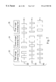
- FIG. 3 is a block diagram of a color scanner according to the present invention.
- FIG. 4 is a schematic diagram of intensity and time-sequence of three light sources of a color scanner according to the first embodiment of the present invention.
- FIG. 5 is a schematic diagram of intensity and time-sequence of three light sources of a color scanner according to the second embodiment of the present invention.
- FIG. 6 is a schematic diagram of “on” time and time-sequence of three light sources of a color scanner according to the third embodiment of the present invention.
- FIG. 7 is a schematic diagram of “on” time and time-sequence of three light sources of a color scanner according to the fourth embodiment of the present invention.
- FIG. 3 is a block diagram of a color scanner 50 according to the present invention.
- the scanner 50 comprises red, green, and blue light sources 52 , 54 , 56 for emitting red, green and blue lights to illuminate a document to be scanned, a scanning module 58 for scanning the lights transmitted from the document to generate three sets of final color image signals of the document, and a control circuit 68 for controlling the three light sources 52 , 54 , 56 and the scanning module 58 .
- the scanning module 58 comprises a plurality of linearly arranged light sensors 60 for sensing the light transmitted from each of the three light sources 52 , 54 , 56 .
- the three light sources 52 , 54 , 56 are individually connected with the correspondent switches 62 , 64 , 66 .
- the control circuit 68 controls the three light sources 52 , 54 , 56 through the three switches 62 , 64 , 66 .
- the three light sources 52 , 54 , 56 can be three light emitting diodes of different colors.
- the scanner 50 is taken as a system, then the red, green, and blue light sources 52 , 54 , 56 are inputs of this system (R, G, B) and the three image signals obtained after the scanning module 58 scans the document can be considered outputs of the system (R′, G′, B′).
- the corresponding outputs (R′, G′, B′) can be obtained.
- R′c r 1 * Ro+r 2 * Go+r 3 * Bo
- G′c g 1 * Ro+g 2 * Go+g 3 * Bo
- the three-color calibrated image signal can be obtained from the scanning module and then it can be combined to form the true color image of this calibration document.
- these calibration parameters of the three light sources may be used to control the brightness of the three light sources and to scan other documents, then the true-color image signal of the document can be obtained.
- the color scanning method of the color scanner 50 comprises the following steps:
- T1 [ 0.9 0.07 0.04 0.07 1.03 - 0.05 - 0.03 - 0.04 1.04 ] ;
- the following are four embodiments of the color image scanning method of the present invention. The difference between them is the manner of controlling the three light sources according to each of the three sets of color calibration parameters.
- FIG. 4 is a schematic diagram of intensity and time-sequence of three light sources of a color scanner according to the first embodiment of the present invention.
- the control circuit 68 can turn on the three light sources 52 , 54 , 56 simultaneously and adjust the brightness of the three light sources 52 , 54 , 56 according to the proportion (0.9Ro,0.07Go,0.04Bo). This causes the scanning module 58 to directly output the red image signal.
- the control circuit 68 turns on the red light source 52 and green light source 54 according to the proportion (0.07Ro,1.03Go) to control its individual brightness.
- FIG. 5 is a schematic diagram of intensity and time-sequence of three light sources of a color scanner according to the second embodiment of the present invention.
- the control circuit 68 uses each color calibration parameter to adjust the electrical current passed to the corresponding light source so as to control its brightness.
- the control circuit 68 turns on the three light sources 52 , 54 , 56 in turn and adjusts the currents passing through them according to the absolute value of each of the three sets of color calibration parameters (0.9Ro,0.07Go,0.04Bo), (0.07Ro,1.03Go,0.05Bo), and (0.03Ro,0.04Go,1.04Bo) to obtain the output of the scanning module 58 .
- the different height of each of the rectangles represents the different brightness of each of the light sources due to differences in current flow.
- FIG. 6 is a schematic diagram of “on” time and time-sequence of three light sources of a color scanner according to the third embodiment of the present invention. Similar to the second embodiment, the control circuit 68 sequentially turns on the three light sources 52 , 54 , 56 . However, in this scheme, the period of time that the light sources are turned on is adjusted according to the absolute value of the calibrating parameters (0.9Ro,0.07Go,0.04Bo), (0.07Ro,1.03Go,0.05Bo), and (0.03Ro,0.04Go,1.04Bo) to obtain the corresponding outputs of the scanning module 58 . In FIG. 6, the rectangles of different lengths represent different lengths of time the light sources are turned on.
- FIG. 7 is a schematic diagram of “on” time and time-sequence of three light sources of a color scanner according to the fourth embodiment of thee present invention. Similar to the third embodiment, the control circuit 68 sequentially turns on the three light sources 52 , 54 , 56 . However, the length of time each light source is turned on is very short and the light sources are turned on and off multiple times while obtaining a color scanning line. The total amount of time the light sources are turned on is proportional to the corresponding calibrating parameter. This allows the scanning module to generate a corresponding output.
- the advantage of this method of taking samples in which many samples in each color scanning line is taken is that it achieves uniformity in spacing and promotes accuracy in representation.
- color image scanning method of the color scanner of the present invention three sets of color calibration parameters are used to adjust three light sources when scanning the document. Each color scanning line is obtained by the three light sources, and then the three scanning lines are combined into a final image signal.
Landscapes
- Engineering & Computer Science (AREA)
- Multimedia (AREA)
- Signal Processing (AREA)
- Facsimile Scanning Arrangements (AREA)
Abstract
Description


Claims (9)
Applications Claiming Priority (2)
| Application Number | Priority Date | Filing Date | Title |
|---|---|---|---|
| TW088100223A TW420927B (en) | 1999-01-08 | 1999-01-08 | Image scanning and color correction method for scanner |
| TW88100223A | 1999-01-08 |
Publications (1)
| Publication Number | Publication Date |
|---|---|
| US6417938B1 true US6417938B1 (en) | 2002-07-09 |
Family
ID=21639326
Family Applications (2)
| Application Number | Title | Priority Date | Filing Date |
|---|---|---|---|
| US09/298,554 Expired - Fee Related US6388775B1 (en) | 1999-01-08 | 1999-04-22 | Image scanner with an automatic document feeder and a movable light source |
| US09/303,679 Expired - Lifetime US6417938B1 (en) | 1999-01-08 | 1999-05-03 | Color image scanning method of a color image scanner |
Family Applications Before (1)
| Application Number | Title | Priority Date | Filing Date |
|---|---|---|---|
| US09/298,554 Expired - Fee Related US6388775B1 (en) | 1999-01-08 | 1999-04-22 | Image scanner with an automatic document feeder and a movable light source |
Country Status (2)
| Country | Link |
|---|---|
| US (2) | US6388775B1 (en) |
| TW (1) | TW420927B (en) |
Cited By (5)
| Publication number | Priority date | Publication date | Assignee | Title |
|---|---|---|---|---|
| US6975418B1 (en) * | 1999-03-02 | 2005-12-13 | Canon Kabushiki Kaisha | Copying machine, image processing apparatus, image processing system and image processing method |
| US20060114521A1 (en) * | 2004-12-01 | 2006-06-01 | Bailey James R | Method and apparatus for improving color registration in contact-image-sensor scanners |
| US20070097386A1 (en) * | 2005-10-31 | 2007-05-03 | Tregoning Michael A | Imaging system and method |
| US20100056049A1 (en) * | 2008-09-04 | 2010-03-04 | Darwin Hu | Wireless Mobile Telescanners |
| US20140351733A1 (en) * | 2013-05-23 | 2014-11-27 | Ramin Soheili | Systems and methods for programming embedded devices using graphical user interface |
Families Citing this family (6)
| Publication number | Priority date | Publication date | Assignee | Title |
|---|---|---|---|---|
| JP4078902B2 (en) * | 2002-07-09 | 2008-04-23 | 富士ゼロックス株式会社 | Image reading device |
| US7359097B2 (en) * | 2003-07-11 | 2008-04-15 | Nisca Corporation | Document feeder and image reading apparatus with the same |
| JP2008129257A (en) * | 2006-11-20 | 2008-06-05 | Murata Mach Ltd | Image forming apparatus |
| US7907311B2 (en) * | 2007-02-13 | 2011-03-15 | Hewlett-Packard Development Company, L.P. | Scanner with an adjustable light source for scanning opaque and transparent media |
| JP7247783B2 (en) * | 2019-06-25 | 2023-03-29 | セイコーエプソン株式会社 | Image reader |
| JP7383977B2 (en) * | 2019-10-21 | 2023-11-21 | セイコーエプソン株式会社 | Image reading device |
Citations (9)
| Publication number | Priority date | Publication date | Assignee | Title |
|---|---|---|---|---|
| US5696608A (en) * | 1992-04-20 | 1997-12-09 | Canon Kabushiki Kaisha | Image reading apparatus capable of controlling light emission amount |
| US5721623A (en) * | 1994-05-06 | 1998-02-24 | U.S. Philips Corporation | Method and device for adjusting a hard-copy-unit |
| US5745262A (en) * | 1995-10-16 | 1998-04-28 | Fuji Photo Film Co., Ltd. | Image read-out and processing apparatus having a parameter correction circuit |
| US6011906A (en) * | 1992-05-10 | 2000-01-04 | Minolta Co., Ltd. | Image system in which a parameter for correcting image data read out by a scanner is generated automatically to suit a printer |
| US6118557A (en) * | 1994-12-07 | 2000-09-12 | Ricoh Company, Ltd. | Color image forming apparatus |
| US6172771B1 (en) * | 1997-04-22 | 2001-01-09 | Canon Kabushiki Kaisha | Image forming system and calibration method for image forming conditions |
| US6222934B1 (en) * | 1998-07-17 | 2001-04-24 | Mustek Systems Inc. | Test chart for determining the image quality of an optical scanner |
| US6275309B1 (en) * | 1998-09-16 | 2001-08-14 | Syscan, Inc. | Lightweight mobile scanners |
| US6320668B1 (en) * | 1997-07-10 | 2001-11-20 | Samsung Electronics Co., Ltd. | Color correction apparatus and method in an image system |
Family Cites Families (5)
| Publication number | Priority date | Publication date | Assignee | Title |
|---|---|---|---|---|
| US5898508A (en) * | 1993-06-09 | 1999-04-27 | Bekanich; Joseph A. | Apparatus for producing multi-dimensional images or reproductions of three dimensional objects |
| JPH08116408A (en) * | 1994-08-24 | 1996-05-07 | Nikon Corp | Surface light source and image reading device |
| JP3342317B2 (en) * | 1996-09-25 | 2002-11-05 | 株式会社ピーエフユー | Support structure of optical unit of image reading device |
| JP3418308B2 (en) * | 1997-05-01 | 2003-06-23 | 株式会社リコー | Image forming device |
| TW361032B (en) * | 1998-01-22 | 1999-06-11 | Benq Corp | Scanner with upper and lower light sources and movable upside light source shield |
-
1999
- 1999-01-08 TW TW088100223A patent/TW420927B/en not_active IP Right Cessation
- 1999-04-22 US US09/298,554 patent/US6388775B1/en not_active Expired - Fee Related
- 1999-05-03 US US09/303,679 patent/US6417938B1/en not_active Expired - Lifetime
Patent Citations (9)
| Publication number | Priority date | Publication date | Assignee | Title |
|---|---|---|---|---|
| US5696608A (en) * | 1992-04-20 | 1997-12-09 | Canon Kabushiki Kaisha | Image reading apparatus capable of controlling light emission amount |
| US6011906A (en) * | 1992-05-10 | 2000-01-04 | Minolta Co., Ltd. | Image system in which a parameter for correcting image data read out by a scanner is generated automatically to suit a printer |
| US5721623A (en) * | 1994-05-06 | 1998-02-24 | U.S. Philips Corporation | Method and device for adjusting a hard-copy-unit |
| US6118557A (en) * | 1994-12-07 | 2000-09-12 | Ricoh Company, Ltd. | Color image forming apparatus |
| US5745262A (en) * | 1995-10-16 | 1998-04-28 | Fuji Photo Film Co., Ltd. | Image read-out and processing apparatus having a parameter correction circuit |
| US6172771B1 (en) * | 1997-04-22 | 2001-01-09 | Canon Kabushiki Kaisha | Image forming system and calibration method for image forming conditions |
| US6320668B1 (en) * | 1997-07-10 | 2001-11-20 | Samsung Electronics Co., Ltd. | Color correction apparatus and method in an image system |
| US6222934B1 (en) * | 1998-07-17 | 2001-04-24 | Mustek Systems Inc. | Test chart for determining the image quality of an optical scanner |
| US6275309B1 (en) * | 1998-09-16 | 2001-08-14 | Syscan, Inc. | Lightweight mobile scanners |
Cited By (6)
| Publication number | Priority date | Publication date | Assignee | Title |
|---|---|---|---|---|
| US6975418B1 (en) * | 1999-03-02 | 2005-12-13 | Canon Kabushiki Kaisha | Copying machine, image processing apparatus, image processing system and image processing method |
| US20060114521A1 (en) * | 2004-12-01 | 2006-06-01 | Bailey James R | Method and apparatus for improving color registration in contact-image-sensor scanners |
| US20070097386A1 (en) * | 2005-10-31 | 2007-05-03 | Tregoning Michael A | Imaging system and method |
| US20100056049A1 (en) * | 2008-09-04 | 2010-03-04 | Darwin Hu | Wireless Mobile Telescanners |
| US20140351733A1 (en) * | 2013-05-23 | 2014-11-27 | Ramin Soheili | Systems and methods for programming embedded devices using graphical user interface |
| US9521729B2 (en) * | 2013-05-23 | 2016-12-13 | Ramin Soheili | Systems and methods for programming embedded devices using graphical user interface |
Also Published As
| Publication number | Publication date |
|---|---|
| US6388775B1 (en) | 2002-05-14 |
| TW420927B (en) | 2001-02-01 |
Similar Documents
| Publication | Publication Date | Title |
|---|---|---|
| KR100734465B1 (en) | Illumination brightness and color control system and method therefor | |
| CN104299565B (en) | The low gray scale correction method and system of LED display | |
| US8004545B2 (en) | Display apparatus with arrangement to decrease quantity of backlight and increase transmittance of the display panel | |
| US6417938B1 (en) | Color image scanning method of a color image scanner | |
| KR101212617B1 (en) | Lighting device and method for the control | |
| EP1077444A2 (en) | System and method for on-chip calibration of illumination sources for an integrated circuit display | |
| US20080297066A1 (en) | Illumination Device and Method for Controlling an Illumination Device | |
| US20030111533A1 (en) | RGB led based white light control system with quasi-uniform color metric | |
| US20100097412A1 (en) | Light source device and liquid crystal display unit | |
| JP2006147171A (en) | Light source device | |
| CN110824768A (en) | Backlight module and display device | |
| JP3790693B2 (en) | Electronic color chart device | |
| KR20080086282A (en) | Driving device of the backlight unit | |
| JPH01179913A (en) | LCD color display backlight and color balance adjustment device | |
| US8803788B2 (en) | Method of driving light-emitting diodes by controlling maximum amount of light and backlight assembly for performing the method | |
| CN101551071A (en) | Lighting device and displaying device using the lighting device | |
| JP2008251460A (en) | Backlight device, backlight control method, and liquid crystal display device | |
| TWI426489B (en) | Image display device and method of controlling a display device | |
| CN211350061U (en) | Control device for automatically lighting LED screen | |
| KR100599371B1 (en) | Display device with automatic brightness control | |
| KR20240006042A (en) | Methods and related display devices for compensating colors based on luminance adjustment parameters | |
| CN105101515A (en) | Lamp driving method and device | |
| EP2108884A1 (en) | Backlight light control | |
| CN101017261A (en) | Liquid crystal display device | |
| JPS60130257A (en) | Color original reader |
Legal Events
| Date | Code | Title | Description |
|---|---|---|---|
| AS | Assignment |
Owner name: UMX DATA SYSTEMS INC., TAIWAN Free format text: ASSIGNMENT OF ASSIGNORS INTEREST;ASSIGNORS:HSU, CHUAN;LEE, CHEN-HO;REEL/FRAME:009944/0327 Effective date: 19990420 |
|
| STCF | Information on status: patent grant |
Free format text: PATENTED CASE |
|
| FPAY | Fee payment |
Year of fee payment: 4 |
|
| AS | Assignment |
Owner name: VEUTRON CORPORATION, TAIWAN Free format text: CHANGE OF NAME;ASSIGNOR:UMAX DATA SYSTEMS INC.;REEL/FRAME:016800/0203 Effective date: 20021029 |
|
| AS | Assignment |
Owner name: TRANSPACIFIC IP, LTD.,TAIWAN Free format text: ASSIGNMENT OF ASSIGNORS INTEREST;ASSIGNOR:VEUTRON CORPORATION;REEL/FRAME:017564/0747 Effective date: 20050706 Owner name: TRANSPACIFIC IP, LTD., TAIWAN Free format text: ASSIGNMENT OF ASSIGNORS INTEREST;ASSIGNOR:VEUTRON CORPORATION;REEL/FRAME:017564/0747 Effective date: 20050706 |
|
| AS | Assignment |
Owner name: TRANSPACIFIC SYSTEMS, LLC, DELAWARE Free format text: ASSIGNMENT OF ASSIGNORS INTEREST;ASSIGNOR:TRANSPACIFIC IP LTD.;REEL/FRAME:023107/0267 Effective date: 20090618 Owner name: TRANSPACIFIC SYSTEMS, LLC,DELAWARE Free format text: ASSIGNMENT OF ASSIGNORS INTEREST;ASSIGNOR:TRANSPACIFIC IP LTD.;REEL/FRAME:023107/0267 Effective date: 20090618 |
|
| FPAY | Fee payment |
Year of fee payment: 8 |
|
| AS | Assignment |
Owner name: TITUSVILLE CANAVERAL LLC, DELAWARE Free format text: MERGER;ASSIGNOR:TRANSPACIFIC SYSTEMS, LLC;REEL/FRAME:030628/0681 Effective date: 20130213 |
|
| AS | Assignment |
Owner name: INTELLECTUAL VENTURES I LLC, DELAWARE Free format text: MERGER;ASSIGNOR:TITUSVILLE CANAVERAL LLC;REEL/FRAME:030639/0330 Effective date: 20130214 |
|
| FPAY | Fee payment |
Year of fee payment: 12 |
|
| AS | Assignment |
Owner name: HANGER SOLUTIONS, LLC, GEORGIA Free format text: ASSIGNMENT OF ASSIGNORS INTEREST;ASSIGNOR:INTELLECTUAL VENTURES ASSETS 161 LLC;REEL/FRAME:052159/0509 Effective date: 20191206 |
|
| AS | Assignment |
Owner name: INTELLECTUAL VENTURES ASSETS 161 LLC, DELAWARE Free format text: ASSIGNMENT OF ASSIGNORS INTEREST;ASSIGNOR:INTELLECTUAL VENTURES I LLC;REEL/FRAME:051945/0001 Effective date: 20191126 |