US6414768B1 - Optical communication system - Google Patents
Optical communication system Download PDFInfo
- Publication number
- US6414768B1 US6414768B1 US09/186,150 US18615098A US6414768B1 US 6414768 B1 US6414768 B1 US 6414768B1 US 18615098 A US18615098 A US 18615098A US 6414768 B1 US6414768 B1 US 6414768B1
- Authority
- US
- United States
- Prior art keywords
- optical
- subscriber
- transmitting
- optical fiber
- devices
- Prior art date
- Legal status (The legal status is an assumption and is not a legal conclusion. Google has not performed a legal analysis and makes no representation as to the accuracy of the status listed.)
- Expired - Fee Related
Links
Images


Classifications
-
- H—ELECTRICITY
- H04—ELECTRIC COMMUNICATION TECHNIQUE
- H04B—TRANSMISSION
- H04B10/00—Transmission systems employing electromagnetic waves other than radio-waves, e.g. infrared, visible or ultraviolet light, or employing corpuscular radiation, e.g. quantum communication
- H04B10/27—Arrangements for networking
- H04B10/275—Ring-type networks
- H04B10/2755—Ring-type networks with a headend
-
- H—ELECTRICITY
- H04—ELECTRIC COMMUNICATION TECHNIQUE
- H04B—TRANSMISSION
- H04B10/00—Transmission systems employing electromagnetic waves other than radio-waves, e.g. infrared, visible or ultraviolet light, or employing corpuscular radiation, e.g. quantum communication
- H04B10/03—Arrangements for fault recovery
- H04B10/035—Arrangements for fault recovery using loopbacks
-
- H—ELECTRICITY
- H04—ELECTRIC COMMUNICATION TECHNIQUE
- H04B—TRANSMISSION
- H04B10/00—Transmission systems employing electromagnetic waves other than radio-waves, e.g. infrared, visible or ultraviolet light, or employing corpuscular radiation, e.g. quantum communication
- H04B10/07—Arrangements for monitoring or testing transmission systems; Arrangements for fault measurement of transmission systems
- H04B10/075—Arrangements for monitoring or testing transmission systems; Arrangements for fault measurement of transmission systems using an in-service signal
- H04B10/077—Arrangements for monitoring or testing transmission systems; Arrangements for fault measurement of transmission systems using an in-service signal using a supervisory or additional signal
- H04B10/0771—Fault location on the transmission path
-
- H—ELECTRICITY
- H04—ELECTRIC COMMUNICATION TECHNIQUE
- H04B—TRANSMISSION
- H04B10/00—Transmission systems employing electromagnetic waves other than radio-waves, e.g. infrared, visible or ultraviolet light, or employing corpuscular radiation, e.g. quantum communication
- H04B10/27—Arrangements for networking
-
- H—ELECTRICITY
- H04—ELECTRIC COMMUNICATION TECHNIQUE
- H04J—MULTIPLEX COMMUNICATION
- H04J3/00—Time-division multiplex systems
- H04J3/02—Details
- H04J3/14—Monitoring arrangements
-
- H—ELECTRICITY
- H04—ELECTRIC COMMUNICATION TECHNIQUE
- H04J—MULTIPLEX COMMUNICATION
- H04J3/00—Time-division multiplex systems
- H04J3/16—Time-division multiplex systems in which the time allocation to individual channels within a transmission cycle is variable, e.g. to accommodate varying complexity of signals, to vary number of channels transmitted
- H04J3/1694—Allocation of channels in TDM/TDMA networks, e.g. distributed multiplexers
-
- H—ELECTRICITY
- H04—ELECTRIC COMMUNICATION TECHNIQUE
- H04Q—SELECTING
- H04Q11/00—Selecting arrangements for multiplex systems
- H04Q11/0001—Selecting arrangements for multiplex systems using optical switching
- H04Q11/0062—Network aspects
-
- H—ELECTRICITY
- H04—ELECTRIC COMMUNICATION TECHNIQUE
- H04B—TRANSMISSION
- H04B2210/00—Indexing scheme relating to optical transmission systems
- H04B2210/07—Monitoring an optical transmission system using a supervisory signal
- H04B2210/078—Monitoring an optical transmission system using a supervisory signal using a separate wavelength
-
- H—ELECTRICITY
- H04—ELECTRIC COMMUNICATION TECHNIQUE
- H04Q—SELECTING
- H04Q11/00—Selecting arrangements for multiplex systems
- H04Q11/0001—Selecting arrangements for multiplex systems using optical switching
- H04Q11/0062—Network aspects
- H04Q11/0067—Provisions for optical access or distribution networks, e.g. Gigabit Ethernet Passive Optical Network (GE-PON), ATM-based Passive Optical Network (A-PON), PON-Ring
-
- H—ELECTRICITY
- H04—ELECTRIC COMMUNICATION TECHNIQUE
- H04Q—SELECTING
- H04Q11/00—Selecting arrangements for multiplex systems
- H04Q11/0001—Selecting arrangements for multiplex systems using optical switching
- H04Q11/0062—Network aspects
- H04Q2011/0079—Operation or maintenance aspects
- H04Q2011/0081—Fault tolerance; Redundancy; Recovery; Reconfigurability
-
- H—ELECTRICITY
- H04—ELECTRIC COMMUNICATION TECHNIQUE
- H04Q—SELECTING
- H04Q11/00—Selecting arrangements for multiplex systems
- H04Q11/0001—Selecting arrangements for multiplex systems using optical switching
- H04Q11/0062—Network aspects
- H04Q2011/0079—Operation or maintenance aspects
- H04Q2011/0083—Testing; Monitoring
Definitions
- the present invention relates to an optical communication system using an optical branching/coupling device.
- an office device accommodates subscriber devices that need a high speed and large capacity communication through exclusive optical fibers (transmission lines) respectively.
- PON Passive Optical Network
- the PON is, as shown in FIG. 11, provided with an optical branching/coupling element between the subscriber devices and the office device.
- the optical branching/coupling element is a passive device that does not need an electric source.
- the office device is connected to the optical branching/coupling element through a single optical fiber or a double optical fiber due to redundancy.
- Each of the subscriber devices is connected to the optical branching/coupling element through an exclusive optical fiber.
- the optical branching/coupling element distributes a downstream optical signal from the office device toward each of the subscriber devices. And also, the element combines an upstream optical signal from the subscriber device toward the office device.
- TDMA Time Division Multiple Access
- TDM Time Division Multiplexing
- the PON can reduce construction cost of the communication system compared with the on-to-one connection in FIG. 10 because of sharing the optical fiber between the office device and the optical branching/coupling element. Further, since the PON uses the passive device as the optical branching/coupling element, it improves the system reliability in maintenance compared with the system using a passive element to multiplex the optical signal.
- each of the subscriber devices and the optical branching/coupling element are connected by the single optical fiber in the PON, it has a low system reliability in a resistance to a transmission line fault such as a disconnection of the optical fiber.
- An optical ring network is known as the other type of the conventional optical communication system.
- the optical ring network includes an optical fiber arranged like a ring and data flow only one direction in the optical fiber.
- the subscriber devices are connected at any points to the transmission line.
- the optical ring network since the data flow in one direction, the disconnection of the optical fiber or a cut off of the power supply of the node device results the system down due to stop of data flow.
- a bypath function and/or a loopback function are usually prepared in the optical ring network.
- FIG. 12 shows the bypath function.
- the bypath function forms the data flow along the route shown in a broken line without passing the node device. In the normal state, the data flow along the route shown in a solid line via the node device.
- any faults in the optical transmission line control the node devices, which are located with the fault portion between, to turn back the data flow and to form a new loop. It is the loopback function.
- the ring network is provided with optical switches to exchange the optical fibers for the bypath function and/or the loopback function.
- a conventional optical ring network is, for example, disclosed in Japanese laid-open patent publication No. Sho 57-1866855.
- the network disclosed in the publication employs an 1-to-n optical communication system that includes a center device, n pieces of remote devices and an optical fiber loop that connects the devices.
- the number n is an integer that equals to or is larger than 2.
- the center device switches the data transmitting mode using the optical switch. In a first mode, the center device transmits the data in one direction to the transmission line. In a second mode, the center device transmits the data in both directions via an optical branching element.
- the remote devices pick up and receive the data (the optical signal) from the transmission line in spite of the direction of the data flow.
- the disconnection of the optical fiber changes the transmission mode from the first mode to the second mode so that all of the remote devices are able to receive the optical data signal.
- the center device since there is an one side communication from the center device to the remote devices in the conventional ring network, the center device cannot specify the fault portion in the transmission optical fiber.
- the present invention is aim to provide an optical communication system, which includes an optical branching/coupling element, can certainly detect a transmission line fault such as a disconnection of an optical fiber.
- an optical communication system includes:
- an office device that includes a pair of optical transmitting/receiving devices for act and standby systems
- a subscriber line that is a ring network of an optical fiber of which one terminal is connected to the optical transmitting/receiving device of the act system and the other terminal is connected to the optical transmitting/receiving device of the standby system;
- optical branching/coupling elements that are passive elements arranged on the subscriber line
- the controlling device actuates the optical transmitting/receiving device of the act system in normal state and actuates both of the optical transmitting/receiving devices when the detecting means detect any faults.
- the subscriber line is a single core optical fiber.
- the office device further comprises means for transmitting a test signal
- each of the subscriber devices includes means for transmitting a response signal corresponding to the test signal and the detecting means specifies fault point based on the response signals from the subscriber devices.
- the optical branching/coupling element comprises first, second and third optical couplers that are connected one another to form a triangle network.
- the first optical coupler distributes light from the act system between the connected subscriber device and the subscriber line at the standby system side
- the second optical coupler distributes light from the standby system between the connected subscriber device and the subscriber line at the act system side
- the third optical coupler distributes light from the connected subscriber device between the act system and the standby system.
- the distribution ratios of the first, second and third optical couplers may be determined based on the location of the connected subscriber device in the ring network.
- the distribution ratio of the connected subscriber device side to the subscriber line side at the first optical coupler is assumed as m:n
- this ratios at the second optical coupler should be n:m
- the distribution ratio of the act system side to the standby system side at the third optical coupler should be m:n.
- increased distance from the optical transmitting/receiving device of the act system increases the value of m, but decreases the value of n.
- FIG. 1 shows a configuration of a first embodiment according to the present invention
- FIG. 2 is a block diagram showing configuration of an OSU
- FIG. 3 shows a frame construction of TDM/TDMA
- FIG. 4 shows a connection state of an optical directional coupler and subscriber devices
- FIG. 5 shows a switching state of the system in the ring network of the first embodiment
- FIG. 6 shows a finding method of a damaged (trouble) portion according to the first embodiment
- FIG. 7 shows an example of optical coupler of fiber type device (an optical directional coupler)
- FIG. 8 shows an example of an optical star coupler
- FIG. 9 shows a configuration of a second embodiment according to the present invention.
- FIG. 10 shows a conventional optical communication system
- FIG. 11 shows a conventional PON system
- FIG. 12 shows the node device which uses an optical bypath switch
- FIG. 13 shows a loopback function of a conventional optical ring network.
- an optical communication system of a first embodiment which employs the PON system, is provided with a subscriber line 1 as an optical transmission line that is arranged as a loop using a single core optical fiber.
- the terminals of the subscriber line 1 are connected to an office device 2 .
- One terminal of the subscriber line 1 is connected to a first OSU (Optical Service Unit) 3 a as an optical transmitting/receiving device provided in an office device 2 and the other terminal is connected to a second OSU 3 b included in the office device 2 .
- the first OSU 3 a uses the subscriber line 1 from one side as an act system and the second OSU 3 b uses the same line 1 from the other side as a standby system.
- the subscriber line 1 is used as a double transmission line.
- the office device 2 further comprises a control unit 3 c to control the first and second OSU 3 a and 3 b. The functions of the control unit 3 c will be described below.
- the first OSU 3 a is, as shown in FIG. 2, provided with a downstream frame generating circuit 4 as a transmitting device and an upstream frame processing circuit 5 as a receiving device.
- the circuit 4 is connected to the optical fiber via an electric-optic converter E/O.
- the circuit 5 is connected to the optical fiber via an optic-electric converter O/E and a delay detecting circuit 6 .
- the second OSU 3 b is also provided with the same circuits as the first OSU 3 a.
- a plurality of optical star couplers 7 are located as an optical branching/coupling element.
- Each of subscriber devices (Optical Node Unit; ONU# 1 , ONU# 2 , . . . , ONU#n) 8 is connected to the corresponding optical star coupler 7 , and thus the subscriber devices 8 are accommodated by a continuous loop of the optical fiber. That is, a subscriber devices 8 and an optical star coupler 7 are connected to each other through a double transmission line.
- An optical star coupler 7 is a passive element that does not need a power source.
- Every subscriber device 8 employs TDMA (Time Division Multiple Access) for the upstream communication and TDM (Time Division Multiplexing) for downstream communication as shown in FIG. 3 .
- TDMA Time Division Multiple Access
- TDM Time Division Multiplexing
- the subscriber device 8 is connected to the looped subscriber line 1 via an optical directional coupler 10 as shown in FIG. 4 .
- the subscriber device 8 includes a node circuit 13 that is connected to the optical directional coupler 10 via an optic-electric convertor 11 and an electric-optic convertor 12 .
- the subscriber device 8 transmits a delay detection frame as a response signal.
- the delay detecting circuits 6 of the first and second OSU 3 a and 3 b measure the delay times to specify the subscriber device that transmits the delay detecting frame.
- the first and second OSU 3 a and 3 b inform the control unit 3 c of the detection of the delay detecting frame.
- the control unit 3 c determines there are no faults in the subscriber line 1 and starts the first OSU 3 a for a communication.
- Each of the subscriber devices 8 receives the downstream frame transmitted from the first OSU 3 a via the optical star coupler 7 . And also, an upstream frame from a subscriber device 8 is received by the first OSU 3 a. Absence of fault allows a suspension of the second OSU 3 b.
- the control unit 3 c determines there are any faults in the subscriber line 1 and actuates the second OSU 3 b as well as the first OSU 3 a . That is, both of the first and second OSU 3 a and 3 b are used for communication. As a result, the subscriber devices 8 at the one side of the fault portion communicate with the first OSU 3 a of the act system, and the devices 8 at the other side of the fault portion communicate with the second OSU 3 b of the standby system.
- control unit 3 c is able to detect the fault point based on results of the received delay detecting frames.
- the optical communication system comprises a fault detecting means that detects fault generated in the subscriber line 1 .
- the function of the fault detecting means is distributed to the OSU 3 a , the control unit 3 c and the subscriber device 8 .
- the OSU 3 a transmits a test signal
- the subscriber device 8 returns the response signal
- the control unit 3 c determines whether any faults occur based on the received response signal.
- the control unit 3 c further provides a function of the controlling means that actuates the first OSU 3 a in normal state and actuates both of the OSU 3 a and 3 b when any faults are detected.
- a disconnection of the subscriber line 1 between the ONU#(n ⁇ 1) and the ONU#n results the communication between the subscriber devices ONU# 1 , ONU# 2 , . . . , ONU#(n ⁇ 1) and the first OSU 3 a of the act system and the communication between the subscriber device ONU#n and the second OSU 3 b of the standby system.
- each of the subscriber devices 8 transmits the delay detection frame for the office device 2 to specify the fault point.
- the office device 2 specifies the fault point based on the condition of the delay detecting frame received by the OSU 3 a and 3 b .
- the fault point will be determined as shown in TABLE 1.
- the subscriber line 1 is segmented into a plurality of portions F# 0 , F# 1 , . . . , F#n.
- the receiving of all of the delay detecting frames at the OSU 3 a and 3 b indicates the normal state of the subscriber line 1 as in the case (a).
- the delay detecting frame from ONU# 1 is received at first OSU 3 a but not received at second OSU 3 b , it is determined that the subscriber line 1 is disconnected at the segment F# 1 between the ONU#l and the ONU# 2 .
- the specification of the disconnection point based on the receiving condition of the delay detecting frames decreases time required for restoration of the subscriber line 1 .
- the second OSU 3 b of the standby system is also used when the subscriber line 1 is disconnected in order to add a new subscriber device. It decreases time for stopping the communication for establishing more subscriber devices.
- FIG. 7 shows an example of an optical coupler (an optical directional coupler) of a fiber type device that is an element of the optical star coupler 7 .
- Light input in a port ( 1 ) is distributed to ports ( 3 ) and ( 4 ) but not to a port ( 2 ).
- light input in the port ( 3 ) is distributed to the ports ( 1 ) and ( 2 ) but not to the port ( 4 ).
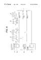
- FIG. 8 shows one example of a specific construction of the optical star coupler 7 that consists of first, second and third optical couplers # 1 , # 2 and # 3 .
- the first optical coupler # 1 distributes light from the act system between the connected subscriber device 8 and the subscriber line 1 at the standby system side.
- the second optical coupler # 2 distributes light from the standby system between the connected subscriber device 8 and the subscriber line 1 at the act system side.
- the third optical coupler # 3 distributes light from the connected subscriber device 8 between the act system and the standby system.
- the distribution ratios of the optical couplers # 1 , # 2 and # 3 are determined based on the location of the connected subscriber device 8 in the ring network. If the distribution ratio of the connected subscriber device side to the subscriber line side at the first optical coupler is assumed as m:n, this ratios at the second optical coupler should be n:m, the distribution ratio of the act system side to the standby system side at the third optical coupler should be m:n. In such the case, increased distance from the first OSU 3 a of the act system increases the value of m, but decreases the value of n.
- the optical coupler # 1 has light distribution ratio of 10:90
- the optical coupler # 2 has the ratio of 90:10
- the coupler # 3 has the ratio of 10:90.
- Light input in the optical coupler # 1 is distributed to the optical coupler # 2 by 90% and to the optical coupler # 3 by 10%.
- Light input in the optical coupler # 2 is distributed to the optical coupler # 1 by 10% and to the optical coupler # 3 by 90%.
- Light input in the optical coupler # 3 is distributed to the optical couplers # 1 by 10% and to the optical coupler # 2 by 90%.
- FIG. 9 shows an optical communication system of a second embodiment that comprises optical star couplers having various distribution ratios.
- the optical star coupler 7 connected to the subscriber device ONU# 1 consists of optical couplers # 1 , # 2 and # 3 of which distribution ratios are 10:90, 90:10 and 10:90 respectively.
- the closest location to the first OSU. 3 a of the act system results small loss of light quantity for a downstream frame from the first OSU 3 a. This allows a small branching percentage (10%) from the subscriber line 1 to the ONU#n at the side of the act system.
- the farthest location from the second OSU 3 b of the standby system results large loss of light quantity for a downstream frame from the second OSU 3 b. This requires a large branching percentage (90%) from the subscriber line 1 to the ONU# 1 at the side of the standby system.
- the optical coupler # 3 distributes the delay detecting frame from the ONU# 1 to the first OSU 3 a by 10% and to the second OSU 3 b by 90%.
- the optical star coupler 7 connected to the subscriber device ONU#m consists of optical couplers # 1 , # 2 and # 3 of which distribution ratios are 50:50.
- the optical coupler # 1 branches 50% of the downstream frame from the first OSU 3 a to the ONU#m.
- the downstream frame from the second OSU 3 b is branched by 50% to the ONU#m at the optical coupler # 2 .
- the optical coupler # 3 distributes the delay detecting frame or the upstream frame from the ONU#m to the first OSU 3 a by 50% and to the second OSU 3 b by 50% too.
- the optical star coupler 7 connected to the subscriber device ONU#n consists of optical couplers # 1 , # 2 and # 3 of which distribution ratios are 90:10, 10:90 and 90:10 respectively.
- the closest location to the second OSU 3 b of the standby system results small loss of light quantity for a downstream frame from the second OSU 3 b. This allows a small branching percentage (10%) from the subscriber line 1 to the ONU#n at the side of the standby system.
- the farthest location from the first OSU 3 a of the act system results large loss of light quantity for a downstream frame from the first OSU 3 a. This requires a large branching percentage (90%) from the subscriber line 1 to the ONU#n at the side of the act system.
- the optical coupler # 3 distributes the delay detecting frame from the ONU#n to the first OSU 3 a by 90% and to the second OSU 3 b by 10%.
- optical couplers having desired distribution ratios allows effective light distribution for each of the subscriber devices, which allows long distance communication.
- the communication systems of the embodiments employ redundant (double) connection between the office device 2 and each of the subscriber devices 8 through the single core optical fiber, which increases communication reliability.
- the communication systems of the embodiments provide the following advantages over the conventional ring network.
- One piece of a single core optical fiber can be used as the subscriber line.
Landscapes
- Engineering & Computer Science (AREA)
- Computer Networks & Wireless Communication (AREA)
- Signal Processing (AREA)
- Physics & Mathematics (AREA)
- Electromagnetism (AREA)
- Computing Systems (AREA)
- Optical Communication System (AREA)
Abstract
Description
| TABLE 1 | ||||
| | OSU | 3a of | |
|
| Device | Act system | Standby system | Determination | |
| (a) |
Receive All | Receive All | Normal | |
| (b) |
Not Receive | Receive All | Disconnect F#0 | |
| (c) |
Receive | Not Receive | Disconnect F#1 | |
| (d) ONU#2 | Receive | Not Receive | |
|
| . | ||||
| . | ||||
| . | ||||
| (n) ONU#n | Receive | Not Receive | Disconnect F#(n−1) | |
Claims (5)
Applications Claiming Priority (2)
| Application Number | Priority Date | Filing Date | Title |
|---|---|---|---|
| JP10-071785 | 1998-03-20 | ||
| JP10071785A JPH11275028A (en) | 1998-03-20 | 1998-03-20 | Optical communication system |
Publications (1)
| Publication Number | Publication Date |
|---|---|
| US6414768B1 true US6414768B1 (en) | 2002-07-02 |
Family
ID=13470586
Family Applications (1)
| Application Number | Title | Priority Date | Filing Date |
|---|---|---|---|
| US09/186,150 Expired - Fee Related US6414768B1 (en) | 1998-03-20 | 1998-11-05 | Optical communication system |
Country Status (2)
| Country | Link |
|---|---|
| US (1) | US6414768B1 (en) |
| JP (1) | JPH11275028A (en) |
Cited By (26)
| Publication number | Priority date | Publication date | Assignee | Title |
|---|---|---|---|---|
| US20020109875A1 (en) * | 2001-02-12 | 2002-08-15 | Eijk Peter Van | Fast protection switching by snooping on downstream signals in an optical network |
| US20020109876A1 (en) * | 2001-02-12 | 2002-08-15 | Peter Van Eijk | Fast protection switching by snooping on upstream signals in an optical network |
| US20030058505A1 (en) * | 2001-09-26 | 2003-03-27 | Joseph Arol | Passive distribution of wavelengths in optical networks |
| US20030095314A1 (en) * | 2001-10-25 | 2003-05-22 | Tatsuya Shimada | Optical communication system with optical output level control function |
| US20030156845A1 (en) * | 2000-04-05 | 2003-08-21 | Persson Ulf A | Optical communication system with two parallel transmission paths |
| US6778781B2 (en) | 2001-02-12 | 2004-08-17 | Lucent Technologies Inc. | Health check algorithm for protection circuit in optical network |
| US20050019031A1 (en) * | 2003-07-25 | 2005-01-27 | Nokia Corporation | Single-fiber protection in telecommunications networks |
| US20050088964A1 (en) * | 2003-10-28 | 2005-04-28 | Tzu-Jian Yang | Ethernet passive optical network ring and its method of authorization and collision detection |
| US20050163147A1 (en) * | 2001-06-06 | 2005-07-28 | Buabbud George H. | Wavelength division multiplexed (WDM) ring passive optical network (PON) with route protection for replacement of splitter based passive optical networks |
| US6978090B1 (en) * | 2000-07-31 | 2005-12-20 | Nortel Networks Limited | Optical network architecture |
| US20060039396A1 (en) * | 2004-08-18 | 2006-02-23 | Nec Corporation | Communication system, communication apparatus and method for accommodating subscriber line |
| US7076563B1 (en) * | 2000-01-31 | 2006-07-11 | Mitsubishi Denki Kabushiki Kaisha | Digital content downloading system using networks |
| WO2006117311A1 (en) * | 2005-05-03 | 2006-11-09 | Ericsson Ab | Passive optical test termination |
| EP1746858A1 (en) * | 2005-07-20 | 2007-01-24 | Siemens Aktiengesellschaft | Three way coupler for a passive optical network |
| US7272321B1 (en) * | 1999-05-10 | 2007-09-18 | Alloptic, Inc. | Passive optical network |
| US20090074403A1 (en) * | 2007-09-19 | 2009-03-19 | Industrial Technology Research Institute | Self-healing ring-based passive optical network |
| US7603033B1 (en) * | 2001-06-28 | 2009-10-13 | Netapp, Inc. | Fault tolerant optical data communication network |
| US20090269062A1 (en) * | 2004-08-27 | 2009-10-29 | Dieter Jestel | Ship with a data network |
| US20150381275A1 (en) * | 2014-06-26 | 2015-12-31 | Adva Optical Networking Se | Optical Coupler Device and an Optical Monitoring Device for Monitoring One or More Optical Point-to-Point Transmission Links |
| US20160112136A1 (en) * | 2013-05-24 | 2016-04-21 | Telefonaktiebolaget Lm Ericsson (Publ) | Optical device, optical distribution network and respective methods performed thereby |
| US20170111717A1 (en) * | 2013-12-04 | 2017-04-20 | Solid, Inc. | Relay system in ring topology |
| US20220224562A1 (en) * | 2019-06-13 | 2022-07-14 | Nippon Telegraph And Telephone Corporation | Communication system and communication method |
| US20230142562A1 (en) * | 2020-04-14 | 2023-05-11 | Nippon Telegraph And Telephone Corporation | Optical communication system and master station |
| US20230146851A1 (en) * | 2020-03-06 | 2023-05-11 | Nippon Telegraph And Telephone Corporation | Communication system and olt system |
| US11956009B2 (en) | 2020-03-17 | 2024-04-09 | Nippon Telegraph And Telephone Corporation | Optical communication system and optical communication method |
| US20250125883A1 (en) * | 2023-10-16 | 2025-04-17 | China Electronics Technology Group Corporation No 44 Research Institute | Integrated source generation, transmission, and distribution system based on photonic loop |
Families Citing this family (8)
| Publication number | Priority date | Publication date | Assignee | Title |
|---|---|---|---|---|
| KR100337131B1 (en) * | 1999-10-14 | 2002-05-18 | 윤덕용 | Bi-directional, subcarrier-multiplexed self-healing ring optical network |
| KR100775690B1 (en) * | 2002-10-01 | 2007-11-09 | 엘지노텔 주식회사 | Ranging Circuit in Passive Optical Subscriber Network in Asynchronous Transmission Mode |
| KR100569825B1 (en) * | 2003-08-07 | 2006-04-11 | 최준국 | Alternating media converter and up-down equal-wavelength ring-type DVD PON system |
| JP6101623B2 (en) * | 2013-12-11 | 2017-03-22 | ミハル通信株式会社 | Optical transmission system and center device |
| JP6924651B2 (en) * | 2017-08-18 | 2021-08-25 | ホーチキ株式会社 | Tunnel emergency equipment |
| WO2022059181A1 (en) * | 2020-09-18 | 2022-03-24 | 三菱電機株式会社 | Single-core bidirectional optical ring system, control method of single-core bidirectional optical ring system, and central station |
| US20250317201A1 (en) * | 2022-06-22 | 2025-10-09 | Nippon Telegraph And Telephone Corporation | Remote optical fiber switching node and its monitoring method |
| WO2026028382A1 (en) * | 2024-08-01 | 2026-02-05 | Ntt株式会社 | Optical path switching system and optical path switching method |
Citations (16)
| Publication number | Priority date | Publication date | Assignee | Title |
|---|---|---|---|---|
| JPS57186855A (en) | 1981-05-13 | 1982-11-17 | Nec Corp | Optical communication system |
| US5345438A (en) * | 1991-08-22 | 1994-09-06 | Nec Corporation | Transmission device capable of readily controlling active and backup sections |
| US5523870A (en) * | 1993-12-17 | 1996-06-04 | Nippon Telegraph And Telephone Corporation | Optical transmission system |
| US5539564A (en) * | 1993-09-22 | 1996-07-23 | Nippon Telegraph And Telephone Corporation | Point-to-multipoint optical transmission system |
| US5576875A (en) * | 1994-04-13 | 1996-11-19 | France Telecom | Telecommunications network organized in reconfigurable wavelength-division-multiplexed optical loops |
| US5680234A (en) * | 1994-10-20 | 1997-10-21 | Lucent Technologies Inc. | Passive optical network with bi-directional optical spectral slicing and loop-back |
| US5717795A (en) * | 1994-02-17 | 1998-02-10 | Kabushiki Kaisha Toshiba | Optical wavelength division multiplexed network system |
| US5737338A (en) * | 1993-07-19 | 1998-04-07 | Fujitsu Limited | ATM exchange and method of testing same |
| US5796501A (en) * | 1995-07-12 | 1998-08-18 | Alcatel N.V. | Wavelength division multiplexing optical communication network |
| US5949563A (en) * | 1997-01-28 | 1999-09-07 | Fujitsu Limited | Wavelength division multiplexing transmitter receiver, optical transmission system, and redundant system switching method |
| US6072610A (en) * | 1996-04-15 | 2000-06-06 | Fujitsu Limited | Optical transmission system |
| US6108112A (en) * | 1997-03-19 | 2000-08-22 | Fujitsu Limited | Method and apparatus for failure recovery in passive optical network |
| US6137603A (en) * | 1996-10-15 | 2000-10-24 | Nec Corporation | Optical network, optical division and insertion node and recovery system from network failure |
| US6222654B1 (en) * | 1997-08-04 | 2001-04-24 | Lucent Technologies, Inc. | Optical node system for a ring architecture and method thereof |
| US6288809B1 (en) * | 1997-10-20 | 2001-09-11 | Fujitsu Limited | Optical subscriber network system |
| US6304346B1 (en) * | 1997-02-18 | 2001-10-16 | Hitachi, Ltd. | Fault restoration control method and it's apparatus in a communication network |
-
1998
- 1998-03-20 JP JP10071785A patent/JPH11275028A/en active Pending
- 1998-11-05 US US09/186,150 patent/US6414768B1/en not_active Expired - Fee Related
Patent Citations (16)
| Publication number | Priority date | Publication date | Assignee | Title |
|---|---|---|---|---|
| JPS57186855A (en) | 1981-05-13 | 1982-11-17 | Nec Corp | Optical communication system |
| US5345438A (en) * | 1991-08-22 | 1994-09-06 | Nec Corporation | Transmission device capable of readily controlling active and backup sections |
| US5737338A (en) * | 1993-07-19 | 1998-04-07 | Fujitsu Limited | ATM exchange and method of testing same |
| US5539564A (en) * | 1993-09-22 | 1996-07-23 | Nippon Telegraph And Telephone Corporation | Point-to-multipoint optical transmission system |
| US5523870A (en) * | 1993-12-17 | 1996-06-04 | Nippon Telegraph And Telephone Corporation | Optical transmission system |
| US5717795A (en) * | 1994-02-17 | 1998-02-10 | Kabushiki Kaisha Toshiba | Optical wavelength division multiplexed network system |
| US5576875A (en) * | 1994-04-13 | 1996-11-19 | France Telecom | Telecommunications network organized in reconfigurable wavelength-division-multiplexed optical loops |
| US5680234A (en) * | 1994-10-20 | 1997-10-21 | Lucent Technologies Inc. | Passive optical network with bi-directional optical spectral slicing and loop-back |
| US5796501A (en) * | 1995-07-12 | 1998-08-18 | Alcatel N.V. | Wavelength division multiplexing optical communication network |
| US6072610A (en) * | 1996-04-15 | 2000-06-06 | Fujitsu Limited | Optical transmission system |
| US6137603A (en) * | 1996-10-15 | 2000-10-24 | Nec Corporation | Optical network, optical division and insertion node and recovery system from network failure |
| US5949563A (en) * | 1997-01-28 | 1999-09-07 | Fujitsu Limited | Wavelength division multiplexing transmitter receiver, optical transmission system, and redundant system switching method |
| US6304346B1 (en) * | 1997-02-18 | 2001-10-16 | Hitachi, Ltd. | Fault restoration control method and it's apparatus in a communication network |
| US6108112A (en) * | 1997-03-19 | 2000-08-22 | Fujitsu Limited | Method and apparatus for failure recovery in passive optical network |
| US6222654B1 (en) * | 1997-08-04 | 2001-04-24 | Lucent Technologies, Inc. | Optical node system for a ring architecture and method thereof |
| US6288809B1 (en) * | 1997-10-20 | 2001-09-11 | Fujitsu Limited | Optical subscriber network system |
Cited By (49)
| Publication number | Priority date | Publication date | Assignee | Title |
|---|---|---|---|---|
| US7272321B1 (en) * | 1999-05-10 | 2007-09-18 | Alloptic, Inc. | Passive optical network |
| US7076563B1 (en) * | 2000-01-31 | 2006-07-11 | Mitsubishi Denki Kabushiki Kaisha | Digital content downloading system using networks |
| US7450843B2 (en) * | 2000-04-05 | 2008-11-11 | Telefonaktiebolaget L M Ericsson (Publ) | Optical communication system with two parallel transmission paths |
| US20030156845A1 (en) * | 2000-04-05 | 2003-08-21 | Persson Ulf A | Optical communication system with two parallel transmission paths |
| US6978090B1 (en) * | 2000-07-31 | 2005-12-20 | Nortel Networks Limited | Optical network architecture |
| US20020109875A1 (en) * | 2001-02-12 | 2002-08-15 | Eijk Peter Van | Fast protection switching by snooping on downstream signals in an optical network |
| US6778781B2 (en) | 2001-02-12 | 2004-08-17 | Lucent Technologies Inc. | Health check algorithm for protection circuit in optical network |
| US6868232B2 (en) | 2001-02-12 | 2005-03-15 | Lucent Technologies Inc. | Fast protection switching by snooping on upstream signals in an optical network |
| US6771908B2 (en) * | 2001-02-12 | 2004-08-03 | Lucent Technologies Inc. | Fast protection switching by snooping on downstream signals in an optical network |
| US20020109876A1 (en) * | 2001-02-12 | 2002-08-15 | Peter Van Eijk | Fast protection switching by snooping on upstream signals in an optical network |
| US20050163147A1 (en) * | 2001-06-06 | 2005-07-28 | Buabbud George H. | Wavelength division multiplexed (WDM) ring passive optical network (PON) with route protection for replacement of splitter based passive optical networks |
| US7212541B2 (en) * | 2001-06-06 | 2007-05-01 | Bedford Tellabs, Inc. | Wavelength division multiplexed (WDM) ring passive optical network (PON) with route protection for replacement of splitter based passive optical networks |
| US20070201873A1 (en) * | 2001-06-06 | 2007-08-30 | Tellabs Bedford, Inc. | Wavelength Division Multiplexed (WDM) Ring Passive Optical Network (PON) with Route Protection for Replacement of Splitter Based Passive Optical Networks |
| US7603033B1 (en) * | 2001-06-28 | 2009-10-13 | Netapp, Inc. | Fault tolerant optical data communication network |
| US20030058505A1 (en) * | 2001-09-26 | 2003-03-27 | Joseph Arol | Passive distribution of wavelengths in optical networks |
| US20030095314A1 (en) * | 2001-10-25 | 2003-05-22 | Tatsuya Shimada | Optical communication system with optical output level control function |
| US7236708B2 (en) * | 2001-10-25 | 2007-06-26 | Nippon Telegraph And Telephone Corporation | Optical communication system with optical output level control function |
| US8145054B2 (en) * | 2003-07-25 | 2012-03-27 | Schofield Technologies Llc | Single-fiber protection in telecommunications networks |
| US20110164882A1 (en) * | 2003-07-25 | 2011-07-07 | Yinghua Ye | Single-fiber protection in telecommunications networks |
| US7920786B2 (en) * | 2003-07-25 | 2011-04-05 | Schofield Technologies Llc | Single-fiber protection in telecommunications networks |
| US20080273872A1 (en) * | 2003-07-25 | 2008-11-06 | Schofield Technologies Llc | Single-fiber protection in telecommunications networks |
| US7933517B2 (en) | 2003-07-25 | 2011-04-26 | Schofield Technologies Llc | Single-fiber protection in telecommunications networks |
| US20050019031A1 (en) * | 2003-07-25 | 2005-01-27 | Nokia Corporation | Single-fiber protection in telecommunications networks |
| US7369769B2 (en) * | 2003-10-28 | 2008-05-06 | Industrial Technology Research Institute | Ethernet passive optical network ring and its method of authorization and collision detection |
| US20050088964A1 (en) * | 2003-10-28 | 2005-04-28 | Tzu-Jian Yang | Ethernet passive optical network ring and its method of authorization and collision detection |
| US20060039396A1 (en) * | 2004-08-18 | 2006-02-23 | Nec Corporation | Communication system, communication apparatus and method for accommodating subscriber line |
| US7945157B2 (en) * | 2004-08-27 | 2011-05-17 | Siemens Aktiengesellschaft | Ship with a data network |
| US20090269062A1 (en) * | 2004-08-27 | 2009-10-29 | Dieter Jestel | Ship with a data network |
| US20080310837A1 (en) * | 2005-05-03 | 2008-12-18 | Martin Goetzer | Passive Optical Test Termination |
| WO2006117311A1 (en) * | 2005-05-03 | 2006-11-09 | Ericsson Ab | Passive optical test termination |
| US8331777B2 (en) * | 2005-05-03 | 2012-12-11 | Ericsson Ab | Passive optical test termination |
| CN101208885B (en) * | 2005-05-03 | 2013-04-24 | 爱立信股份有限公司 | Passive optical test termination device, network and method thereof |
| WO2007009938A1 (en) * | 2005-07-20 | 2007-01-25 | Nokia Siemens Networks Gmbh & Co. Kg. | Three way coupler for a passive optical network |
| EP1746858A1 (en) * | 2005-07-20 | 2007-01-24 | Siemens Aktiengesellschaft | Three way coupler for a passive optical network |
| US20090074403A1 (en) * | 2007-09-19 | 2009-03-19 | Industrial Technology Research Institute | Self-healing ring-based passive optical network |
| US20160112136A1 (en) * | 2013-05-24 | 2016-04-21 | Telefonaktiebolaget Lm Ericsson (Publ) | Optical device, optical distribution network and respective methods performed thereby |
| US10873795B2 (en) * | 2013-12-04 | 2020-12-22 | Solid. Inc. | Relay system in ring topology |
| US20170111717A1 (en) * | 2013-12-04 | 2017-04-20 | Solid, Inc. | Relay system in ring topology |
| US9917640B2 (en) * | 2014-06-26 | 2018-03-13 | Adva Optical Networking Se | Optical coupler device and an optical monitoring device for monitoring one or more optical point-to-point transmission links |
| US20150381275A1 (en) * | 2014-06-26 | 2015-12-31 | Adva Optical Networking Se | Optical Coupler Device and an Optical Monitoring Device for Monitoring One or More Optical Point-to-Point Transmission Links |
| US20220224562A1 (en) * | 2019-06-13 | 2022-07-14 | Nippon Telegraph And Telephone Corporation | Communication system and communication method |
| US12192032B2 (en) * | 2019-06-13 | 2025-01-07 | Nippon Telegraph And Telephone Corporation | Communication system and communication method |
| US20230146851A1 (en) * | 2020-03-06 | 2023-05-11 | Nippon Telegraph And Telephone Corporation | Communication system and olt system |
| US11936432B2 (en) * | 2020-03-06 | 2024-03-19 | Nippon Telegraph And Telephone Corporation | Communication system and OLT system |
| US11956009B2 (en) | 2020-03-17 | 2024-04-09 | Nippon Telegraph And Telephone Corporation | Optical communication system and optical communication method |
| US20230142562A1 (en) * | 2020-04-14 | 2023-05-11 | Nippon Telegraph And Telephone Corporation | Optical communication system and master station |
| US12040831B2 (en) * | 2020-04-14 | 2024-07-16 | Nippon Telegraph And Telephone Corporation | Optical communication system and master station |
| US20250125883A1 (en) * | 2023-10-16 | 2025-04-17 | China Electronics Technology Group Corporation No 44 Research Institute | Integrated source generation, transmission, and distribution system based on photonic loop |
| US12556288B2 (en) * | 2023-10-16 | 2026-02-17 | China Electronics Technology Group Corporation No 44 Research Institute | Integrated source generation, transmission, and distribution system based on photonic loop |
Also Published As
| Publication number | Publication date |
|---|---|
| JPH11275028A (en) | 1999-10-08 |
Similar Documents
| Publication | Publication Date | Title |
|---|---|---|
| US6414768B1 (en) | Optical communication system | |
| US6327400B1 (en) | Protection scheme for single fiber bidirectional passive optical point-to-multipoint network architectures | |
| US5757526A (en) | Optical communication network and method for optically detecting a fault | |
| EP0545936B1 (en) | A dual-hubbed arrangement to provide a protected ring interconnection | |
| US6587235B1 (en) | Method and apparatus for capacity-efficient restoration in an optical communication system | |
| US6351582B1 (en) | Passive optical network arrangement | |
| US6915075B1 (en) | Protection of WDM-channels | |
| US6295146B1 (en) | System and method for sharing a spare channel among two or more optical ring networks | |
| EP1004184B1 (en) | Self-healing ring network and a method for fault detection and rectifying | |
| EP1064739B1 (en) | Protection of wdm-channels | |
| AU729950B2 (en) | Optical switching unit | |
| US5594581A (en) | Low loss optical transmission/monitoring path selection in redundant equipment terminals | |
| US7305187B2 (en) | Optical communications system | |
| KR20010073397A (en) | Optical Distribution Network in ATM-PON System | |
| JP3123633B2 (en) | 1: n communication transmission method | |
| KR100342758B1 (en) | Apparatus for automatically switching cable in a optical subscriber system | |
| GB2332832A (en) | Path protection with flexible routing | |
| JPH0946298A (en) | Optical star coupler with shutter function | |
| JP7744612B2 (en) | Terminal device, communication device, and switching control method | |
| JPS6142978B2 (en) | ||
| JP2862971B2 (en) | Dendritic information network | |
| JP2926525B2 (en) | Protection system switching method for optical subscriber transmission system. | |
| JP3292178B2 (en) | Optical communication network equipment, optical transmission system and optical communication network | |
| JPS585045A (en) | Optical communication device | |
| JPH06350624A (en) | Line changeover system for interlocking ring |
Legal Events
| Date | Code | Title | Description |
|---|---|---|---|
| AS | Assignment |
Owner name: FUJITSU LIMITED, JAPAN Free format text: ASSIGNMENT OF ASSIGNORS INTEREST;ASSIGNORS:SAKATA, TAKASHI;ARAMAKI, TAKAHIRO;REEL/FRAME:009575/0580 Effective date: 19981023 |
|
| FEPP | Fee payment procedure |
Free format text: PAYER NUMBER DE-ASSIGNED (ORIGINAL EVENT CODE: RMPN); ENTITY STATUS OF PATENT OWNER: LARGE ENTITY Free format text: PAYOR NUMBER ASSIGNED (ORIGINAL EVENT CODE: ASPN); ENTITY STATUS OF PATENT OWNER: LARGE ENTITY |
|
| FPAY | Fee payment |
Year of fee payment: 4 |
|
| FPAY | Fee payment |
Year of fee payment: 8 |
|
| REMI | Maintenance fee reminder mailed | ||
| LAPS | Lapse for failure to pay maintenance fees | ||
| STCH | Information on status: patent discontinuation |
Free format text: PATENT EXPIRED DUE TO NONPAYMENT OF MAINTENANCE FEES UNDER 37 CFR 1.362 |
|
| FP | Lapsed due to failure to pay maintenance fee |
Effective date: 20140702 |