US6407879B1 - Disk drive cover features for spindle resonance tuning and damping - Google Patents
Disk drive cover features for spindle resonance tuning and damping Download PDFInfo
- Publication number
- US6407879B1 US6407879B1 US09/158,743 US15874398A US6407879B1 US 6407879 B1 US6407879 B1 US 6407879B1 US 15874398 A US15874398 A US 15874398A US 6407879 B1 US6407879 B1 US 6407879B1
- Authority
- US
- United States
- Prior art keywords
- disk drive
- slots
- spindle shaft
- top cover
- axis
- Prior art date
- Legal status (The legal status is an assumption and is not a legal conclusion. Google has not performed a legal analysis and makes no representation as to the accuracy of the status listed.)
- Expired - Fee Related
Links
Images


Classifications
-
- G—PHYSICS
- G11—INFORMATION STORAGE
- G11B—INFORMATION STORAGE BASED ON RELATIVE MOVEMENT BETWEEN RECORD CARRIER AND TRANSDUCER
- G11B25/00—Apparatus characterised by the shape of record carrier employed but not specific to the method of recording or reproducing, e.g. dictating apparatus; Combinations of such apparatus
- G11B25/04—Apparatus characterised by the shape of record carrier employed but not specific to the method of recording or reproducing, e.g. dictating apparatus; Combinations of such apparatus using flat record carriers, e.g. disc, card
- G11B25/043—Apparatus characterised by the shape of record carrier employed but not specific to the method of recording or reproducing, e.g. dictating apparatus; Combinations of such apparatus using flat record carriers, e.g. disc, card using rotating discs
-
- G—PHYSICS
- G11—INFORMATION STORAGE
- G11B—INFORMATION STORAGE BASED ON RELATIVE MOVEMENT BETWEEN RECORD CARRIER AND TRANSDUCER
- G11B33/00—Constructional parts, details or accessories not provided for in the other groups of this subclass
- G11B33/02—Cabinets; Cases; Stands; Disposition of apparatus therein or thereon
- G11B33/08—Insulation or absorption of undesired vibrations or sounds
Definitions
- the present invention relates to a cover for a hard disk drive which dampens rocking motion of the spindle motor, reduces the motion of the recording head relative to the disk, decreases the transmission of mechanical vibration from the spindle motor to the top cover and reduces acoustical emissions.
- Hard disk drives are used in personal computer applications for the high volume storage of data. These drives contain a disk assembly and a head arrangement for transferring data to and from tracks disposed concentrically on one or more disk surfaces.
- the disks are mounted to a bearing spindle hub which is rotatable around an inner stationary shaft.
- a motor is typically mounted within or beneath the hub and rotates the disks and hub.
- the first mode of vibration for the disk and hub is in a radial direction relative to the spindle shaft.
- the second mode of vibration for the disk and hub is in an axial direction relative to the spindle shaft.
- the third mode of vibration is a rocking displacement of the disk and hub relative to the spindle shaft. Consequently, vibrational energy transmitted to the spindle-disk assembly may cause servo systems errors and track misregistration, thereby decreasing drive performance.
- a first reason is a result of spindle generated vibrations from ball bearing defects as the bearing spins during operation.
- a ball bearing is not perfectly spherical and generally contains some defect such as a flat spot, crevice or the like. Consequently, the movement of the spindle as the bearing passes each defect produces an excitation which generates vibration in a spindle.
- defect frequencies associated with each spindle speed
- ball bearing excitation frequencies will produce vibrations in any given spindle design.
- a second reason is a result of environmental vibrations or shock. Sources of environmental induced vibrations include but are not limited to physical jarring of the disk drive installed in a computer, or any movement to a computer.
- a third reason is a result of vertical diaphragm vibrations of the head-disk assembly transferred to the spindle-disk assembly.
- the diaphragm mode vibrations are vertical drum-like deformations of the top cover and bottom base plate of a head disk assembly enclosure.
- every given spindle structure inherently has an upper and lower rocking mode as a result of its design in combination with manufacturing tolerances among its component parts, including the structural stiffness of the disk drive housing.
- any given spindle will exhibit specific upper and lower natural rocking resonances, which resonance or frequency will change depending upon the number of disks supported by the spindle, as well as the rotational speed of the disks.
- the rocking resonance can also be excited by the bearing defect frequency (e.g., the number of cycles or number of regular passes of a defected bearing portion in a given amount of time) if the frequency of the natural rocking mode and the bearing defect frequency are close to each other.
- every bearing design has a unique set of bearing defect frequencies based on the geometry of the bearing and the speed at which the bearings spin. As a result, an abnormally large radial vibration of the spindle will be produced when the bearing defect frequency is the same as or close to the natural rocking mode or frequency of the spindle and disk combination, i.e., the upper and lower rocking modes.
- the rocking resonance of the spindle and the overall vibration induced into the spindle-disk combination is further affected by the stiffness of the disk drive housing.
- the spindle is positioned between the base plate and cover of the disk drive housing.
- the stiffness and damping of the base plate and cover can alter and/or dampen the natural rocking resonance of the spindle and the overall vibration of the spindle-disk combination.
- Disk drives with rigid shafts mounted to rigid housings offer minimum damping to attenuate the effects of spindle rocking mode and vertical diaphragm mode resonances caused by environmental shocks and vibrations, and spindle generated excitations from bearing defects, nor does such rigidity shift or alter the natural rocking resonance away from the bearing defect frequency.
- the spindle-disk assembly structure also has a significant effect on the amplitude of vibrations resulting from spindle rocking mode and vertical diaphragm mode resonant frequencies.
- the amplitude of these vibrations is directly associated with drive performance.
- Undamped structures exhibit vibrations of higher amplitude at their resonant frequencies, compared to equivalent structures which contain damping, and thus are more likely to effect servo positioning and track registration. Consequently, for a given vibrational input from a source such as spindle bearing defects, an undamped and rigid disk drive housing containing the spindle-disk assembly will produce larger amplitude vibrations in the spindle at its resonant frequency than an equivalent disk drive housing containing damping.
- first and second viscoelastic dampers effective in attenuating vibrations during operation of a disk drive for improved disk drive performance.
- the first viscoelastic damper is inserted on top of the spindle shaft and in contact with the top cover of the disk enclosure.
- the damper has a layer of viscoelastic material fixed to one side of a washer which is effective to attach the washer to the top cover of the disk enclosure.
- the washer also has an opening at a raised central region to provide access for the attachment of the top cover and the shaft.
- the second viscoelastic damper is positioned outside the disk enclosure in contact with the bottom baseplate. It is constructed of a polyester layer disposed between first and second viscoelastic layers.
- low acoustic noise is an increasingly important performance advantage in the application of hard disk drives.
- hard disk drives designed to operate in personal computers are used in relatively quiet environments. It has been found that a major source of acoustic noise is the excitation of the spindle-disk assembly during normal operation.
- This prior art has several disadvantages.
- an additional mechanical component must be added to the disk drive assembly to attenuate vibrations during operation of the disk drive. This adds cost to the manufacturing of the disk drive.
- the additional mechanical component decreases system reliability as there exists another component subject to mis-assembly or failure.
- this prior art can increase head offsets (relative alignments of heads and disks down the spindle) over time and temperature extremes due to spindle movement because the spindle is not rigidly attached to the cover.
- the present invention allows for tuning the structural stiffness of a spindle in a disk drive, to avoid and/or dampen rocking motion of the spindle motor.
- a preferred embodiment containing principles of the present invention allows for tuning the structural stiffness of a spindle in a disk drive to reduce vibration, including the rocking mode resonance of a disk drive spindle either alone or when excited or enhanced by a complementary bearing defect frequency.
- Modification to the disk drive cover in the area of the spindle in accordance with the principles of the present invention, will reduce the amplitude and/or alter the frequency of the natural rocking resonance mode of the spindle sufficiently either to prevent a previously interacting spindle to no longer interact at a particular bearing defect frequency or to dampen the amplitude of the rocking resonant mode, the bearing defect and overlapping combinative effects of both to reduce the effects of vibrations. This is accomplished by altering the stiffness or spring rate of the disk drive cover or by adding damping. With reductions of the in-plane stiffness of the disk drive cover, substantial reductions or shifting of rocking mode frequency may be accomplished, and vibration is eliminated or substantially reduced.
- One embodiment consists of a series of slots in the top cover, extending radially outwardly from the area of the cover to which the spindle attaches.
- the design allows increased lateral motion of the spindle shaft by facilitating movement in the plane of the cover.
- the slots change the top cover from a homogenous stiff in-plane material, to a series of relatively weaker beams which flex yet contain no directional stiffness dependency.
- the cover can tune the spindle resonance to avoid interaction with the bearing defect frequency, or to dampen any vibrations resulting from the rocking resonance mode or bearing defects, alone or combined.
- circumferential slots are overlaid by a constrained-layer damper which sits in a pocket formed by a raised portion around the perimeter of the top cover. This acts to reduce the motion of the spindle shaft by absorbing energy. Consequently, the combination of a cover having slots allowing for more spindle shaft motion and the constrained-layer damper, changes the spring rate of the top cover and adds further damping to the rotating spindle-disk assembly.
- this embodiment is useful in avoiding an undesirable interaction with the bearing defect frequency and in further damping any interaction that may occur.
- the implementation of this embodiment has been shown to have attained greater than a 50 percent reduction in peak amplitude associated with rocking mode resonance significantly reducing position error.
- a third embodiment consists of a series of spiral slots in the top cover, extending outward from the area of the cover to which the spindle attaches.
- the design alters the top cover from a homogenous stiff in-place material, to a series of relatively weaker beams which flex more easily. In this manner, the natural rocking mode resonance can be altered or shifted away from the bearing defect frequency to avoid overlap and negative interaction. While a damping material may also be incorporated, the damping effects are not as pronounced as in the other described embodiments.
- FIG. 1 is an exploded perspective view of a disk drive
- FIG. 2 is a partial top view of a first embodiment of a top cover
- FIG. 3 is a perspective view of the first embodiment of a top cover
- FIG. 4 is an enlarged partial top view of the first embodiment of a top cover
- FIG. 5 is a perspective view of a second embodiment of a top cover
- FIG. 6 is an isometric view of the constrained-layer damper and first embodiment of the top cover
- FIG. 7 is a top view of a disk drive cover spiral slot configuration
- FIG. 8 is an enlarged top view of a spiral slot configuration
- FIG. 9 is a table showing the relative amplitudes of signals produced by disk drive spin motors incorporating different embodiments of the present invention, compared to solid covers.
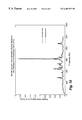
- FIG. 10 is a graph of position error signal versus frequency for a dampened spindle utilizing a 10-ball motor and top cover having a 2-slot configuration and an Avery Adhesive constrained-layer damper.
- disk drive 2 includes a housing 3 containing a spindle 4 secured between a top cover 5 and a bottom base plate 6 .
- a hub 7 is mounted on the spindle 4 and supports disks 8 for rotation about an axis 9 .
- a head assembly (not shown) is provided for reading information from and writing information onto disks 8 as they rotate with the hub 7 .
- the top and bottom of shaft 10 are rigidly mounted to the top cover 5 and bottom baseplate 6 , respectively, by screws or the like.
- Cartridge bearing assemblies support the hub 7 on the shaft 10 to permit rotation of the hub 7 about the shaft 10 .
- a circular 2-slot arrangement 11 is manufactured into the top cover 5 .
- the circular 2-slot arrangement 11 can be machined or stamped as desired, and is positioned around a center raised area 12 which clears the disk clamp 13 .
- the inner slot 14 on cover 5 is broken into halves separated by two closed areas 15 , 180 degrees apart, which can vary in size, but are about 0.120 inches in length.
- the inner slot 14 on cover 5 has a width w 1 that is about 0.100 inches with an inner radius r 1 of about 0.781 inches and outer radius r 2 of about 0.881 inches measured from the spindle axis 9 .
- the outer slot 16 on cover 5 has two halves separated by two closed areas 17 , 180 degrees apart, and are about 0.120 inches in length.
- the outer slot 16 on cover 5 a width w 2 that is about 0.100 inches in length, with an inner radius r 3 of about 0.969 inches and an outer radius r 4 of about 1.069 inches measured from the spindle axis 9 .
- the inner slot 14 closed space 15 is typically positioned 90 degrees from the outer slot 16 and closed space 17 , but the relative position of the inner and outer closed spaces may vary.
- both inner slot 14 , and the outer slot 16 are concentrically centered with respect to the axis 9 of the spindle shaft 10 .
- a circular slot may comprise more than two arcuate segments and the spacing between segments may vary.
- the relative width of the segments may vary and the number of overall circular slots may be more than two.
- FIG. 5 discloses an embodiment with three concentrically arranged rows of slots.
- an exploded view of the cover damper 18 consists of the top cover 5 , the constrained-layer 19 , and the cover sheet 20 positioned on top of the constrained-layer 19 .
- the constrained-layer damper 19 consists of an adhesive material that preferably varies from about 0.002 to about 0.005 inches thick.
- the cover sheet 20 of preferably about 0.020 inches thick is positioned on top of the adhesive for protection.
- the constrained-layer damper adhesive can either be Avery Adhesive or 3M ISD-112, which is an acrylic acoustic material with a silicone reduced Mylar liner. The Avery Adhesive is manufactured by Avery Denison Co., Painsville, Ohio.
- the 3M ISD-112 is manufactured by 3M, Minneapolis, Minn.
- the disk drive top cover 5 can be selected from the group consisting of plastic, aluminum or stainless steel.
- the cover sheet 20 is positioned to protect the adhesive and may be selected from the group consisting of plastic, aluminum or stainless steel.
- the results from tests comparing first and second slotted embodiments of the present invention to a standard solid cover is set forth in the table reproduced as FIG. 9 .
- the drives tested utilized a circular 2-slot configuration, with either an Avery Adhesive constrained-ayer damper or a 3M ISD-112 constrained-layer damper, and a 3-slot configuration with an Avery Adhesive constrained-layer damper. All test results show a reduction in spindle rocking mode peak amplitude and a reduction or shifting of frequency.
- cover damper 18 comprising the top cover 5 , the constrained layer damper 19 and cover sheet 20 , is effective in damping the vibration of the spindle to reduce the effects of the natural rocking mode and any interaction of the natural rocking mode with the bearing defect frequency.
- the implementation as shown in FIGS. 1 and 5 attained more than a 50 percent reduction in spindle rocking mode peak amplitude.
- FIG. 10 a graph comparing the position error signal of a disk drive containing a solid cover or a 2-slot cover as shown in FIGS. 1-4, and further comprising a 10-ball motor operating at 5400 revolutions per minute, the embodiment of FIGS. 1-4 provides a 74 percent reduction of position error signal (PES) based upon percentage of track measurements, compared to a solid cover.
- PES position error signal
- FIGS. 7 and 8 depict another embodiment of the principles of the present invention comprising a series of spiral slots machined or stamped into the disk drive top cover.
- the top cover 21 comprises a plurality of equally spaced spiral slots 22 oriented clockwise.
- the top cover 21 may comprise a plurality of equally spaced spiral slots 22 oriented counter-clockwise.
- FIG. 8 shows a spiral slot 22 configuration consisting of 8 slots oriented clockwise.
- the spiral slots 22 are arranged in 45 degree increments.
- the inside edge 23 of the spiral slot 22 has a radius r 5 of about 0.287 inches and the outside edge 24 of the spiral slot 22 has a radius r 6 of about 0.387 inches.
- the circular end 26 of spiral slot 22 has a radius r 7 of about 0.050 inches, and the circular end 28 of spiral slot 22 has a radius r 8 of about 0.050 inches.
- the outside radius r 9 of the circular end 26 of the spiral slot 22 has a radius of about 0.527 inches from the axis 9 .
- the inside radius r 10 of the circular end 28 of the spiral slot 22 has a radius of about 0.263 inches from the axis 9 .
- the space between the center of circular end 26 and the center of circular end 28 is an angle of about 65 degrees. There exists a plurality of different sizes for the inside edge 23 , outside edge 24 , outside radius 25 , circular end 26 , inside radius 27 , and circular end 28 , depending on the required application.
- the spiral shaped slots also change the top cover from a homogeneous stiff in-plane material, to a series of relatively weaker beams which flex more easily yet contain no directional stiffness.
- This configuration changes the stiffness (e.g., spring rate) of the disk drive top cover compared to a solid cover.
- the spiral shape enhances in-plane flexing of the top cover in the area of the spindle.
- the spiral slots may be oriented either clockwise or counter-clockwise. By modifying the length, angle and width of the spiral slots, varying reductions of in-plane stiffiess are available. While this design provides some damping, it primarily alters or shifts the static rocking mode frequency to reduce the likelihood of interference or overlap between the static rocking mode frequency and the bearing defect frequency.
Landscapes
- Moving Of Heads (AREA)
Abstract
Description
Claims (55)
Priority Applications (1)
| Application Number | Priority Date | Filing Date | Title |
|---|---|---|---|
| US09/158,743 US6407879B1 (en) | 1998-09-22 | 1998-09-22 | Disk drive cover features for spindle resonance tuning and damping |
Applications Claiming Priority (1)
| Application Number | Priority Date | Filing Date | Title |
|---|---|---|---|
| US09/158,743 US6407879B1 (en) | 1998-09-22 | 1998-09-22 | Disk drive cover features for spindle resonance tuning and damping |
Publications (1)
| Publication Number | Publication Date |
|---|---|
| US6407879B1 true US6407879B1 (en) | 2002-06-18 |
Family
ID=22569497
Family Applications (1)
| Application Number | Title | Priority Date | Filing Date |
|---|---|---|---|
| US09/158,743 Expired - Fee Related US6407879B1 (en) | 1998-09-22 | 1998-09-22 | Disk drive cover features for spindle resonance tuning and damping |
Country Status (1)
| Country | Link |
|---|---|
| US (1) | US6407879B1 (en) |
Cited By (20)
| Publication number | Priority date | Publication date | Assignee | Title |
|---|---|---|---|---|
| US20030072103A1 (en) * | 2001-05-10 | 2003-04-17 | Kang Seong Woo | Apparatus and method for dampening disk vibration in storage devices |
| US6643251B1 (en) * | 1999-03-09 | 2003-11-04 | Sony Corporation | Disc drive apparatus |
| US20050111134A1 (en) * | 2003-11-22 | 2005-05-26 | Samsung Electronics Co., Ltd. | Disk drive having anti-shock structure |
| EP1566798A1 (en) * | 2004-02-19 | 2005-08-24 | Samsung Electronics Co., Ltd. | Hard disk drive |
| US6950275B1 (en) * | 2002-06-26 | 2005-09-27 | Western Digital Technologies, Inc. | Disk drive having cover assembly which compresses a foam member between substantially planar rigid members |
| US20060007601A1 (en) * | 2004-07-07 | 2006-01-12 | Samsung Electronics Co., Ltd | Base plate and hard disk drive provided therewith |
| US7031104B1 (en) * | 2002-04-30 | 2006-04-18 | Western Digital Technologies, Inc. | Disk drive having guide-vanes |
| US20060087763A1 (en) * | 2004-06-17 | 2006-04-27 | Creative Technology Ltd. | Case |
| US20060171064A1 (en) * | 2001-05-10 | 2006-08-03 | Samsung Electronics Co., Ltd. | Method and apparatus for improved disk damper in a hard disk drive |
| US20060259917A1 (en) * | 2005-05-10 | 2006-11-16 | Victor Company Of Japan, Ltd. | Disc apparatus |
| US20070291407A1 (en) * | 2006-05-11 | 2007-12-20 | Maxtor Corporation | Internal support interface with vibration and acoustic isolation |
| US20080163275A1 (en) * | 2006-12-27 | 2008-07-03 | Kabushiki Kaisha Toshiba | Optical disc apparatus |
| US7420771B1 (en) | 2005-01-11 | 2008-09-02 | Western Digital Technologies, Inc. | Disk drive with cover including a metal layer and a polymer layer with a polymer layer feature |
| US20090154018A1 (en) * | 2007-12-15 | 2009-06-18 | Seagate Technology Llc | Shrouding a data storage disc with disc facing surfaces that define protuberant features |
| US8553356B1 (en) | 2011-11-21 | 2013-10-08 | Western Digital Technologies, Inc. | Disk limiter for disk drive |
| US8743509B1 (en) | 2010-05-10 | 2014-06-03 | Western Digital Technologies, Inc. | Disk drive having a head loading ramp and a disk limiter tab that projects from a side of an actuator arm |
| US8797677B2 (en) * | 2011-12-15 | 2014-08-05 | Western Digital Technologies, Inc. | Disk deflection damper for disk drive |
| US8995119B2 (en) | 2009-03-17 | 2015-03-31 | Mmi Precision Forming Pte Ltd. | Low cost high performance injection molded hard drive top cover |
| CN110390961A (en) * | 2019-08-02 | 2019-10-29 | 浙江志创企业管理有限公司 | A kind of mechanical hard disk vibration damping protection fixed equipment |
| US11308994B2 (en) | 2020-04-20 | 2022-04-19 | Seagate Technology Llc | Top cover spring designs |
Citations (6)
| Publication number | Priority date | Publication date | Assignee | Title |
|---|---|---|---|---|
| US5004207A (en) * | 1988-11-11 | 1991-04-02 | International Business Machines Corporation | Shock mounting structure and magnetic disk apparatus |
| US5725931A (en) * | 1995-11-03 | 1998-03-10 | Minnesota Mining And Manufacturing Company | Constrained layer damper with slit(s) and/or cutout(s) |
| US5757580A (en) * | 1996-11-27 | 1998-05-26 | Seagate Technology, Inc. | Constrain layer damping of a disc drive printed wiring assembly |
| US5790344A (en) * | 1997-05-22 | 1998-08-04 | International Business Machines Corporation | Base casting/cover for separating pack bounce and spindle tilt modes in a magnetic storage system |
| US5875067A (en) * | 1991-03-22 | 1999-02-23 | Seagate Technology, Inc. | Acoustic isolator for a disc drive assembly |
| US5898537A (en) * | 1996-03-26 | 1999-04-27 | Fujitsu Limited | Storage device having an improved housing structure |
-
1998
- 1998-09-22 US US09/158,743 patent/US6407879B1/en not_active Expired - Fee Related
Patent Citations (7)
| Publication number | Priority date | Publication date | Assignee | Title |
|---|---|---|---|---|
| US5004207A (en) * | 1988-11-11 | 1991-04-02 | International Business Machines Corporation | Shock mounting structure and magnetic disk apparatus |
| US5875067A (en) * | 1991-03-22 | 1999-02-23 | Seagate Technology, Inc. | Acoustic isolator for a disc drive assembly |
| US6081406A (en) * | 1991-03-22 | 2000-06-27 | Seagate Technology, Inc. | Peripherally extending acoustic compliance area in a disc drive housing |
| US5725931A (en) * | 1995-11-03 | 1998-03-10 | Minnesota Mining And Manufacturing Company | Constrained layer damper with slit(s) and/or cutout(s) |
| US5898537A (en) * | 1996-03-26 | 1999-04-27 | Fujitsu Limited | Storage device having an improved housing structure |
| US5757580A (en) * | 1996-11-27 | 1998-05-26 | Seagate Technology, Inc. | Constrain layer damping of a disc drive printed wiring assembly |
| US5790344A (en) * | 1997-05-22 | 1998-08-04 | International Business Machines Corporation | Base casting/cover for separating pack bounce and spindle tilt modes in a magnetic storage system |
Cited By (31)
| Publication number | Priority date | Publication date | Assignee | Title |
|---|---|---|---|---|
| US6643251B1 (en) * | 1999-03-09 | 2003-11-04 | Sony Corporation | Disc drive apparatus |
| US7697236B2 (en) | 2001-05-10 | 2010-04-13 | Samsung Electronics Co., Ldt. | Method and apparatus for disk damper extending across all data tracks of a rotating disk surface upwind of the voice coil actuator in a hard disk drive |
| US20030072103A1 (en) * | 2001-05-10 | 2003-04-17 | Kang Seong Woo | Apparatus and method for dampening disk vibration in storage devices |
| US20060171064A1 (en) * | 2001-05-10 | 2006-08-03 | Samsung Electronics Co., Ltd. | Method and apparatus for improved disk damper in a hard disk drive |
| US6961207B2 (en) * | 2001-05-10 | 2005-11-01 | Samsung Electronics Co., Ltd. | Apparatus and method for dampening disk vibration in storage devices |
| US7031104B1 (en) * | 2002-04-30 | 2006-04-18 | Western Digital Technologies, Inc. | Disk drive having guide-vanes |
| US6950275B1 (en) * | 2002-06-26 | 2005-09-27 | Western Digital Technologies, Inc. | Disk drive having cover assembly which compresses a foam member between substantially planar rigid members |
| US7355812B2 (en) | 2003-11-22 | 2008-04-08 | Institute For Information Technology Advancement | Disk drive having anti-shock structure |
| KR100552702B1 (en) * | 2003-11-22 | 2006-02-20 | 삼성전자주식회사 | Disk drive with shockproof structure |
| US20050111134A1 (en) * | 2003-11-22 | 2005-05-26 | Samsung Electronics Co., Ltd. | Disk drive having anti-shock structure |
| US20050185325A1 (en) * | 2004-02-19 | 2005-08-25 | Samsung Electronics Co., Ltd. | Hard disk drive |
| EP1566798A1 (en) * | 2004-02-19 | 2005-08-24 | Samsung Electronics Co., Ltd. | Hard disk drive |
| CN100409361C (en) * | 2004-02-19 | 2008-08-06 | 三星电子株式会社 | Hard disk drive |
| US7450338B2 (en) | 2004-02-19 | 2008-11-11 | Samsung Electronics Co., Ltd. | Hard disk drive cover with protruding blades for reducing disk and HGA vibration |
| US20060087763A1 (en) * | 2004-06-17 | 2006-04-27 | Creative Technology Ltd. | Case |
| US20060007601A1 (en) * | 2004-07-07 | 2006-01-12 | Samsung Electronics Co., Ltd | Base plate and hard disk drive provided therewith |
| US7420771B1 (en) | 2005-01-11 | 2008-09-02 | Western Digital Technologies, Inc. | Disk drive with cover including a metal layer and a polymer layer with a polymer layer feature |
| US7526780B2 (en) * | 2005-05-10 | 2009-04-28 | Victor Company Of Japan, Ltd. | Disc apparatus |
| US20060259917A1 (en) * | 2005-05-10 | 2006-11-16 | Victor Company Of Japan, Ltd. | Disc apparatus |
| US20070291407A1 (en) * | 2006-05-11 | 2007-12-20 | Maxtor Corporation | Internal support interface with vibration and acoustic isolation |
| US7889461B2 (en) | 2006-05-11 | 2011-02-15 | Maxtor Corporation | Internal support interface between a shaft and housing member with vibration and acoustic isolation |
| US20080163275A1 (en) * | 2006-12-27 | 2008-07-03 | Kabushiki Kaisha Toshiba | Optical disc apparatus |
| US20090154018A1 (en) * | 2007-12-15 | 2009-06-18 | Seagate Technology Llc | Shrouding a data storage disc with disc facing surfaces that define protuberant features |
| US8885288B2 (en) * | 2007-12-15 | 2014-11-11 | Seagate Technology Llc | Shrouding a data storage disc with disc facing surfaces that define protuberant features |
| US8995119B2 (en) | 2009-03-17 | 2015-03-31 | Mmi Precision Forming Pte Ltd. | Low cost high performance injection molded hard drive top cover |
| US8743509B1 (en) | 2010-05-10 | 2014-06-03 | Western Digital Technologies, Inc. | Disk drive having a head loading ramp and a disk limiter tab that projects from a side of an actuator arm |
| US8553356B1 (en) | 2011-11-21 | 2013-10-08 | Western Digital Technologies, Inc. | Disk limiter for disk drive |
| US8797677B2 (en) * | 2011-12-15 | 2014-08-05 | Western Digital Technologies, Inc. | Disk deflection damper for disk drive |
| CN110390961A (en) * | 2019-08-02 | 2019-10-29 | 浙江志创企业管理有限公司 | A kind of mechanical hard disk vibration damping protection fixed equipment |
| CN110390961B (en) * | 2019-08-02 | 2020-03-10 | 浙江志创企业管理有限公司 | Mechanical hard disk vibration reduction protection fixing equipment |
| US11308994B2 (en) | 2020-04-20 | 2022-04-19 | Seagate Technology Llc | Top cover spring designs |
Similar Documents
| Publication | Publication Date | Title |
|---|---|---|
| US6407879B1 (en) | Disk drive cover features for spindle resonance tuning and damping | |
| US5483397A (en) | Damping configuration for improved disk drive performance | |
| US6809898B1 (en) | Disk drive rocking mode vibration damper | |
| US6883175B2 (en) | Dynamic vibration absorbing apparatus for an optical disk drive | |
| US8416534B1 (en) | Disk drive with asymmetric tolerance ring | |
| KR20040030052A (en) | Disk drive | |
| US5751080A (en) | Spindle motor having hydrodynamic bearing | |
| US6757131B1 (en) | Magnetic disk apparatus | |
| US6064547A (en) | Damped disk separator | |
| US7283324B2 (en) | Disk drive device and method having stabilizer plate located between disks | |
| US6898051B2 (en) | Disc drive spindle motor having a damper on a bottom surface of the spindle motor | |
| US6574099B2 (en) | Disc-drive mounting using adhesive films | |
| KR100271610B1 (en) | Balancing Device of Hard Disk Drive Actuator | |
| US5867348A (en) | Disk drive actuator assembly with rotational imbalance compensation | |
| US7185350B2 (en) | Disk drive adopting vibration absorber | |
| US20010028527A1 (en) | Noise and vibration damping device of rotation driving apparatus | |
| US5925946A (en) | Damping insert and isolation pad to reduce acoustic levels and vibration in motor and disc drive | |
| US20060066993A1 (en) | Disk drive device | |
| US6256288B1 (en) | Disk apparatus and motor therefor | |
| CN100495556C (en) | disk drive | |
| US20020044375A1 (en) | Disk drive apparatus, hard disk drive, and enclosure for hard disk drive | |
| US7331054B2 (en) | Vibration damping means for optical recording/reproducing apparatus | |
| WO2000004542A1 (en) | Disk apparatus | |
| JP2004092905A (en) | Vibration damper and vibration damping method for rotary storage disc of data storage unit | |
| US7835114B2 (en) | Disc drive apparatus |
Legal Events
| Date | Code | Title | Description |
|---|---|---|---|
| AS | Assignment |
Owner name: MAXTOR CORPORATION, COLORADO Free format text: ASSIGNMENT OF ASSIGNORS INTEREST;ASSIGNORS:FRUGE', TAVE J.;SANDOR, MATHEW J.;SCHNEIDER, KRIS D.;AND OTHERS;REEL/FRAME:009492/0001;SIGNING DATES FROM 19980917 TO 19980918 |
|
| FPAY | Fee payment |
Year of fee payment: 4 |
|
| AS | Assignment |
Owner name: WELLS FARGO BANK, NATIONAL ASSOCIATION, AS COLLATERAL AGENT AND SECOND PRIORITY REPRESENTATIVE, CALIFORNIA Free format text: SECURITY AGREEMENT;ASSIGNORS:MAXTOR CORPORATION;SEAGATE TECHNOLOGY LLC;SEAGATE TECHNOLOGY INTERNATIONAL;REEL/FRAME:022757/0017 Effective date: 20090507 Owner name: JPMORGAN CHASE BANK, N.A., AS ADMINISTRATIVE AGENT AND FIRST PRIORITY REPRESENTATIVE, NEW YORK Free format text: SECURITY AGREEMENT;ASSIGNORS:MAXTOR CORPORATION;SEAGATE TECHNOLOGY LLC;SEAGATE TECHNOLOGY INTERNATIONAL;REEL/FRAME:022757/0017 Effective date: 20090507 Owner name: JPMORGAN CHASE BANK, N.A., AS ADMINISTRATIVE AGENT Free format text: SECURITY AGREEMENT;ASSIGNORS:MAXTOR CORPORATION;SEAGATE TECHNOLOGY LLC;SEAGATE TECHNOLOGY INTERNATIONAL;REEL/FRAME:022757/0017 Effective date: 20090507 Owner name: WELLS FARGO BANK, NATIONAL ASSOCIATION, AS COLLATE Free format text: SECURITY AGREEMENT;ASSIGNORS:MAXTOR CORPORATION;SEAGATE TECHNOLOGY LLC;SEAGATE TECHNOLOGY INTERNATIONAL;REEL/FRAME:022757/0017 Effective date: 20090507 |
|
| FPAY | Fee payment |
Year of fee payment: 8 |
|
| AS | Assignment |
Owner name: SEAGATE TECHNOLOGY LLC, CALIFORNIA Free format text: RELEASE;ASSIGNOR:JPMORGAN CHASE BANK, N.A., AS ADMINISTRATIVE AGENT;REEL/FRAME:025662/0001 Effective date: 20110114 Owner name: MAXTOR CORPORATION, CALIFORNIA Free format text: RELEASE;ASSIGNOR:JPMORGAN CHASE BANK, N.A., AS ADMINISTRATIVE AGENT;REEL/FRAME:025662/0001 Effective date: 20110114 Owner name: SEAGATE TECHNOLOGY HDD HOLDINGS, CALIFORNIA Free format text: RELEASE;ASSIGNOR:JPMORGAN CHASE BANK, N.A., AS ADMINISTRATIVE AGENT;REEL/FRAME:025662/0001 Effective date: 20110114 Owner name: SEAGATE TECHNOLOGY INTERNATIONAL, CALIFORNIA Free format text: RELEASE;ASSIGNOR:JPMORGAN CHASE BANK, N.A., AS ADMINISTRATIVE AGENT;REEL/FRAME:025662/0001 Effective date: 20110114 |
|
| AS | Assignment |
Owner name: THE BANK OF NOVA SCOTIA, AS ADMINISTRATIVE AGENT, CANADA Free format text: SECURITY AGREEMENT;ASSIGNOR:SEAGATE TECHNOLOGY LLC;REEL/FRAME:026010/0350 Effective date: 20110118 Owner name: THE BANK OF NOVA SCOTIA, AS ADMINISTRATIVE AGENT, Free format text: SECURITY AGREEMENT;ASSIGNOR:SEAGATE TECHNOLOGY LLC;REEL/FRAME:026010/0350 Effective date: 20110118 |
|
| AS | Assignment |
Owner name: SEAGATE TECHNOLOGY INTERNATIONAL, CAYMAN ISLANDS Free format text: TERMINATION AND RELEASE OF SECURITY INTEREST IN PATENT RIGHTS;ASSIGNOR:WELLS FARGO BANK, NATIONAL ASSOCIATION, AS COLLATERAL AGENT AND SECOND PRIORITY REPRESENTATIVE;REEL/FRAME:030833/0001 Effective date: 20130312 Owner name: EVAULT INC. (F/K/A I365 INC.), CALIFORNIA Free format text: TERMINATION AND RELEASE OF SECURITY INTEREST IN PATENT RIGHTS;ASSIGNOR:WELLS FARGO BANK, NATIONAL ASSOCIATION, AS COLLATERAL AGENT AND SECOND PRIORITY REPRESENTATIVE;REEL/FRAME:030833/0001 Effective date: 20130312 Owner name: SEAGATE TECHNOLOGY LLC, CALIFORNIA Free format text: TERMINATION AND RELEASE OF SECURITY INTEREST IN PATENT RIGHTS;ASSIGNOR:WELLS FARGO BANK, NATIONAL ASSOCIATION, AS COLLATERAL AGENT AND SECOND PRIORITY REPRESENTATIVE;REEL/FRAME:030833/0001 Effective date: 20130312 Owner name: SEAGATE TECHNOLOGY US HOLDINGS, INC., CALIFORNIA Free format text: TERMINATION AND RELEASE OF SECURITY INTEREST IN PATENT RIGHTS;ASSIGNOR:WELLS FARGO BANK, NATIONAL ASSOCIATION, AS COLLATERAL AGENT AND SECOND PRIORITY REPRESENTATIVE;REEL/FRAME:030833/0001 Effective date: 20130312 |
|
| REMI | Maintenance fee reminder mailed | ||
| LAPS | Lapse for failure to pay maintenance fees | ||
| STCH | Information on status: patent discontinuation |
Free format text: PATENT EXPIRED DUE TO NONPAYMENT OF MAINTENANCE FEES UNDER 37 CFR 1.362 |
|
| FP | Lapsed due to failure to pay maintenance fee |
Effective date: 20140618 |
|
| AS | Assignment |
Owner name: SEAGATE TECHNOLOGY PUBLIC LIMITED COMPANY, CALIFORNIA Free format text: RELEASE BY SECURED PARTY;ASSIGNOR:THE BANK OF NOVA SCOTIA;REEL/FRAME:072193/0001 Effective date: 20250303 Owner name: SEAGATE TECHNOLOGY, CALIFORNIA Free format text: RELEASE BY SECURED PARTY;ASSIGNOR:THE BANK OF NOVA SCOTIA;REEL/FRAME:072193/0001 Effective date: 20250303 Owner name: SEAGATE TECHNOLOGY HDD HOLDINGS, CALIFORNIA Free format text: RELEASE BY SECURED PARTY;ASSIGNOR:THE BANK OF NOVA SCOTIA;REEL/FRAME:072193/0001 Effective date: 20250303 Owner name: I365 INC., CALIFORNIA Free format text: RELEASE BY SECURED PARTY;ASSIGNOR:THE BANK OF NOVA SCOTIA;REEL/FRAME:072193/0001 Effective date: 20250303 Owner name: SEAGATE TECHNOLOGY LLC, CALIFORNIA Free format text: RELEASE BY SECURED PARTY;ASSIGNOR:THE BANK OF NOVA SCOTIA;REEL/FRAME:072193/0001 Effective date: 20250303 Owner name: SEAGATE TECHNOLOGY INTERNATIONAL, CAYMAN ISLANDS Free format text: RELEASE BY SECURED PARTY;ASSIGNOR:THE BANK OF NOVA SCOTIA;REEL/FRAME:072193/0001 Effective date: 20250303 Owner name: SEAGATE HDD CAYMAN, CAYMAN ISLANDS Free format text: RELEASE BY SECURED PARTY;ASSIGNOR:THE BANK OF NOVA SCOTIA;REEL/FRAME:072193/0001 Effective date: 20250303 Owner name: SEAGATE TECHNOLOGY (US) HOLDINGS, INC., CALIFORNIA Free format text: RELEASE BY SECURED PARTY;ASSIGNOR:THE BANK OF NOVA SCOTIA;REEL/FRAME:072193/0001 Effective date: 20250303 Owner name: SEAGATE TECHNOLOGY, CALIFORNIA Free format text: RELEASE OF SECURITY INTEREST;ASSIGNOR:THE BANK OF NOVA SCOTIA;REEL/FRAME:072193/0001 Effective date: 20250303 Owner name: SEAGATE TECHNOLOGY PUBLIC LIMITED COMPANY, CALIFORNIA Free format text: RELEASE OF SECURITY INTEREST;ASSIGNOR:THE BANK OF NOVA SCOTIA;REEL/FRAME:072193/0001 Effective date: 20250303 Owner name: SEAGATE TECHNOLOGY HDD HOLDINGS, CALIFORNIA Free format text: RELEASE OF SECURITY INTEREST;ASSIGNOR:THE BANK OF NOVA SCOTIA;REEL/FRAME:072193/0001 Effective date: 20250303 Owner name: I365 INC., CALIFORNIA Free format text: RELEASE OF SECURITY INTEREST;ASSIGNOR:THE BANK OF NOVA SCOTIA;REEL/FRAME:072193/0001 Effective date: 20250303 Owner name: SEAGATE TECHNOLOGY LLC, CALIFORNIA Free format text: RELEASE OF SECURITY INTEREST;ASSIGNOR:THE BANK OF NOVA SCOTIA;REEL/FRAME:072193/0001 Effective date: 20250303 Owner name: SEAGATE TECHNOLOGY INTERNATIONAL, CAYMAN ISLANDS Free format text: RELEASE OF SECURITY INTEREST;ASSIGNOR:THE BANK OF NOVA SCOTIA;REEL/FRAME:072193/0001 Effective date: 20250303 Owner name: SEAGATE HDD CAYMAN, CAYMAN ISLANDS Free format text: RELEASE OF SECURITY INTEREST;ASSIGNOR:THE BANK OF NOVA SCOTIA;REEL/FRAME:072193/0001 Effective date: 20250303 Owner name: SEAGATE TECHNOLOGY (US) HOLDINGS, INC., CALIFORNIA Free format text: RELEASE OF SECURITY INTEREST;ASSIGNOR:THE BANK OF NOVA SCOTIA;REEL/FRAME:072193/0001 Effective date: 20250303 |