US6400536B1 - Low uniaxial anisotropy cobalt iron (COFE) free layer structure for GMR and tunnel junction heads - Google Patents
Low uniaxial anisotropy cobalt iron (COFE) free layer structure for GMR and tunnel junction heads Download PDFInfo
- Publication number
- US6400536B1 US6400536B1 US09/281,238 US28123899A US6400536B1 US 6400536 B1 US6400536 B1 US 6400536B1 US 28123899 A US28123899 A US 28123899A US 6400536 B1 US6400536 B1 US 6400536B1
- Authority
- US
- United States
- Prior art keywords
- layer
- layers
- free
- forming
- magnetic
- Prior art date
- Legal status (The legal status is an assumption and is not a legal conclusion. Google has not performed a legal analysis and makes no representation as to the accuracy of the status listed.)
- Expired - Fee Related
Links
Images


Classifications
-
- G—PHYSICS
- G11—INFORMATION STORAGE
- G11B—INFORMATION STORAGE BASED ON RELATIVE MOVEMENT BETWEEN RECORD CARRIER AND TRANSDUCER
- G11B5/00—Recording by magnetisation or demagnetisation of a record carrier; Reproducing by magnetic means; Record carriers therefor
- G11B5/127—Structure or manufacture of heads, e.g. inductive
- G11B5/33—Structure or manufacture of flux-sensitive heads, i.e. for reproduction only; Combination of such heads with means for recording or erasing only
- G11B5/39—Structure or manufacture of flux-sensitive heads, i.e. for reproduction only; Combination of such heads with means for recording or erasing only using magneto-resistive devices or effects
- G11B5/3903—Structure or manufacture of flux-sensitive heads, i.e. for reproduction only; Combination of such heads with means for recording or erasing only using magneto-resistive devices or effects using magnetic thin film layers or their effects, the films being part of integrated structures
-
- B—PERFORMING OPERATIONS; TRANSPORTING
- B82—NANOTECHNOLOGY
- B82Y—SPECIFIC USES OR APPLICATIONS OF NANOSTRUCTURES; MEASUREMENT OR ANALYSIS OF NANOSTRUCTURES; MANUFACTURE OR TREATMENT OF NANOSTRUCTURES
- B82Y10/00—Nanotechnology for information processing, storage or transmission, e.g. quantum computing or single electron logic
-
- B—PERFORMING OPERATIONS; TRANSPORTING
- B82—NANOTECHNOLOGY
- B82Y—SPECIFIC USES OR APPLICATIONS OF NANOSTRUCTURES; MEASUREMENT OR ANALYSIS OF NANOSTRUCTURES; MANUFACTURE OR TREATMENT OF NANOSTRUCTURES
- B82Y25/00—Nanomagnetism, e.g. magnetoimpedance, anisotropic magnetoresistance, giant magnetoresistance or tunneling magnetoresistance
-
- G—PHYSICS
- G11—INFORMATION STORAGE
- G11B—INFORMATION STORAGE BASED ON RELATIVE MOVEMENT BETWEEN RECORD CARRIER AND TRANSDUCER
- G11B5/00—Recording by magnetisation or demagnetisation of a record carrier; Reproducing by magnetic means; Record carriers therefor
- G11B5/127—Structure or manufacture of heads, e.g. inductive
- G11B5/33—Structure or manufacture of flux-sensitive heads, i.e. for reproduction only; Combination of such heads with means for recording or erasing only
- G11B5/39—Structure or manufacture of flux-sensitive heads, i.e. for reproduction only; Combination of such heads with means for recording or erasing only using magneto-resistive devices or effects
- G11B5/3903—Structure or manufacture of flux-sensitive heads, i.e. for reproduction only; Combination of such heads with means for recording or erasing only using magneto-resistive devices or effects using magnetic thin film layers or their effects, the films being part of integrated structures
- G11B5/3906—Details related to the use of magnetic thin film layers or to their effects
- G11B5/3909—Arrangements using a magnetic tunnel junction
-
- G—PHYSICS
- G11—INFORMATION STORAGE
- G11B—INFORMATION STORAGE BASED ON RELATIVE MOVEMENT BETWEEN RECORD CARRIER AND TRANSDUCER
- G11B5/00—Recording by magnetisation or demagnetisation of a record carrier; Reproducing by magnetic means; Record carriers therefor
- G11B5/127—Structure or manufacture of heads, e.g. inductive
- G11B5/33—Structure or manufacture of flux-sensitive heads, i.e. for reproduction only; Combination of such heads with means for recording or erasing only
- G11B5/39—Structure or manufacture of flux-sensitive heads, i.e. for reproduction only; Combination of such heads with means for recording or erasing only using magneto-resistive devices or effects
- G11B5/3903—Structure or manufacture of flux-sensitive heads, i.e. for reproduction only; Combination of such heads with means for recording or erasing only using magneto-resistive devices or effects using magnetic thin film layers or their effects, the films being part of integrated structures
- G11B5/3967—Composite structural arrangements of transducers, e.g. inductive write and magnetoresistive read
-
- G—PHYSICS
- G11—INFORMATION STORAGE
- G11B—INFORMATION STORAGE BASED ON RELATIVE MOVEMENT BETWEEN RECORD CARRIER AND TRANSDUCER
- G11B5/00—Recording by magnetisation or demagnetisation of a record carrier; Reproducing by magnetic means; Record carriers therefor
- G11B5/127—Structure or manufacture of heads, e.g. inductive
- G11B5/33—Structure or manufacture of flux-sensitive heads, i.e. for reproduction only; Combination of such heads with means for recording or erasing only
- G11B5/39—Structure or manufacture of flux-sensitive heads, i.e. for reproduction only; Combination of such heads with means for recording or erasing only using magneto-resistive devices or effects
- G11B2005/3996—Structure or manufacture of flux-sensitive heads, i.e. for reproduction only; Combination of such heads with means for recording or erasing only using magneto-resistive devices or effects large or giant magnetoresistive effects [GMR], e.g. as generated in spin-valve [SV] devices
Definitions
- the present invention relates to a low uniaxial anisotropy cobalt iron (CoFe) free layer structure for giant magnetoresistive (GMR) and tunnel junction heads and, more particularly, to a multilayered free layer structure wherein the uniaxial anisotropies (H K ) of the layers counterbalance one another to provide a low net uniaxial anisotropy.
- CoFe cobalt iron
- the heart of a computer is an assembly that is referred to as a magnetic disk drive.
- the magnetic disk drive includes a rotating magnetic disk, write and read heads that are suspended by a suspension arm above the rotating disk and an actuator that swings the suspension arm to place the read and write heads over selected circular tracks on the rotating disk.
- the read and write heads are directly mounted on a slider that has an air bearing surface (ABS).
- ABS air bearing surface
- the suspension arm biases the slider into contact with the surface of the disk when the disk is not rotating but, when the disk rotates, air is swirled by the rotating disk adjacent the ABS of the slider causing the slider to ride on an air bearing a slight distance from the surface of the rotating disk.
- the write and read heads are employed for writing magnetic impressions to and reading magnetic impressions from the rotating disk.
- the read and write heads are connected to processing circuitry that operates according to a computer program to implement the writing and reading functions.
- the write head includes a coil layer embedded in first, second and third insulation layers (insulation stack), the insulation stack being sandwiched between first and second pole piece layers.
- a gap is formed between the first and second pole piece layers by a nomnagnetic gap layer at an air bearing surface (ABS) of the write head.
- ABS air bearing surface
- the pole piece layers are connected at a back gap.
- Current conducted to the coil layer induces a magnetic field into the pole pieces that fringes across the gap between the pole pieces at the ABS.
- the fringe field or the lack thereof writes information in tracks on moving media, such as in circular tracks on a rotating disk.
- a spin valve sensor is employed for sensing magnetic fields from the rotating magnetic disk.
- the sensor includes a nonmagnetic conductive layer, hereinafter referred to as a spacer layer, sandwiched between first and second ferromagnetic layers, hereinafter referred to as a pinned layer, and a free layer.
- First and second leads are connected to the spin valve sensor for conducting a sense current therethrough.
- the magnetization of the pinned layer is pinned perpendicular to an air bearing surface (ABS) of the head and the magnetic moment of the free layer is located parallel to the ABS but free to rotate in response to external magnetic fields.
- the magnetization of the pinned layer is typically pinned by exchange coupling with an antiferromagnetic layer.
- the thickness of the spacer layer is chosen to be less than the mean free path of conduction electrons through the sensor. With this arrangement, a portion of the conduction electrons is scattered by the interfaces of the spacer layer with the pinned and free layers. When the magnetizations of the pinned and free layers are parallel with respect to one another, scattering is minimal and when the magnetizations of the pinned and free layers are antiparallel, scattering is maximized. Changes in scattering alter the resistance of the spin valve sensor in proportion to cos ⁇ , where ⁇ is the angle between the magnetizations of the pinned and free layers. In a read mode the resistance of the spin valve sensor changes proportionally to the magnitudes of the magnetic fields from the rotating disk. When a sense current is conducted through the spin valve sensor resistance changes cause potential changes that are detected and processed as playback signals by the processing circuitry.
- the spin valve sensor is characterized by a magnetoresistive (MR) coefficient that is substantially higher than the MR coefficient of an anisotropic magnetoresistive (AMR) sensor.
- MR coefficient is dr/R were dr is the change in resistance of the spin valve sensor and R is the resistance of the spin valve sensor before the change.
- a spin valve sensor is typically referred to as a giant magnetoresistive (GMR) sensor.
- GMR giant magnetoresistive
- the AP pinned spin valve sensor differs from the simple spin valve sensor in that the AP pinned spin valve sensor has an AP pinned structure that has first and second AP pinned layers instead of a single pinned layer. An AP coupling layer is sandwiched between the first and second AP pinned layers. The first AP pinned layer has its magnetic moment oriented in a first direction by exchange coupling to the antiferromagnetic pinning layer. The second AP pinned layer is immediately adjacent to the free layer and is antiparallel exchange coupled to the first AP pinned layer because of the minimal thickness (in the order of 8 ⁇ ) of the AP coupling layer between the first and second AP pinned layers. Accordingly, the magnetic moment of the second AP pinned layer is oriented in a second direction that is antiparallel to the direction of the magnetic moment of the first AP pinned layer.
- a typical tunnel junction sensor has two ferromagnetic layers (i.e., the pinned and free layers) separated by a thin spacer layer which relies upon the phenomenon of spin-polarized electron tunneling.
- the free and pinned layers which may be NiFe or CoFe, are crystalline in structure and are separated by an electrically insulating spacer layer that is thin enough that quantum mechanical tunneling occurs between the free and pinned layers.
- the tunneling phenomenon is electron spin dependent, making the magnetic response of the tunnel junction sensor a function of the relative orientations and spin polarization of the conduction electrons between the free and pinned layers.
- the magnetic moment orientation of the pinned layer should be pinned 90° to the magnetic moment orientation of the free layer, with the magnetic direction of the free layer being able to respond to external magnetic fields.
- the pinned layer has a magnetic moment that is pinned in its orientation by exchange coupling with a pinning layer that is made of an antiferromagnetic material.
- a thin layer of cobalt (Co), and preferably cobalt iron (CoFe), between the free layer and the spacer layer increases the magnetoresistive coefficient (dr/R) of the sensor.
- the thickness of the cobalt (Co) or cobalt iron (CoFe) layer is very thin, such as 10 ⁇ , and for this reason it is sometimes referred to as a nanolayer.
- the nanolayer is exchange coupled to the free layer, which is typically nickel iron (NiFe).
- the nickel iron (NiFe) and the nanolayer are considered collectively as the free layer. Because of their exchange coupling each layer has a magnetic moment that is oriented in the same direction. This direction is parallel to the ABS in a quiescent state, namely when the sensor is not subjected to an applied field (H) from the rotating magnetic disk.
- Each of the nanolayer and the nickel iron (NiFe) layer has a uniaxial anisotropy (H K ).
- Uniaxial anisotropy is the amount of applied field (H) that is required to rotate the magnetic moment of the layer from an easy axis position to 90° thereto. In the case of a free layer it would be the amount of applied field (H) from the rotating magnetic disk required to rotate the magnetic moment of the free layer from a position parallel to the ABS to a position perpendicular to the ABS.
- Nickel iron (NiFe) is a desirable material for a free layer since it has a low uniaxial anisotropy (H K ).
- the cobalt iron (CoFe) or the cobalt (Co) of the nanolayer has a high uniaxial anisotropy (H K ) which makes rotation of the magnetic moment stiff in its response to an applied field (H) from the rotating magnetic disk.
- the high uniaxial anisotropy of the cobalt iron (CoFe) or cobalt (Co) stiffens the response of the combined layers of the nanolayer and the nickel iron (NiFe) layer causing the free layer to be less responsive to applied fields from the rotating magnetic disk.
- the thickness of the cobalt iron (CoFe) or the cobalt (Co) of the nanolayer is kept as thin as possible. While a thickness of 5 ⁇ would be desirable, this is sometimes too thin and results in nonuniformity of the nanolayer. Accordingly, the thickness is generally 10 ⁇ -15 ⁇ .
- H K uniaxial anisotropy
- This problem is a decrease in the flux decay in the free layer between flux inception at the ABS and the top edge of the free layer, which distance is known in the art as the stripe height. Since the sensor is located between first and second ferromagnetic shield layers the flux leaks into the shield layers commencing at the ABS and continues to the top edge of the free layer. This leakage constitutes the aforementioned flux decay.
- Permeability is also related to uniaxial anisotropy (H K ) by
- H K uniaxial anisotropies
- H K uniaxial anisotropies
- a second cobalt iron (CoFe) or cobalt (Co) free layer can be employed on an opposite side of the nickel iron (NiFe) free layer.
- the easy axes of the nanolayer between the nickel iron (NiFe) free layer and the spacer layer may be oriented parallel to the ABS, the easy axis of the nickel iron (NiFe) free layer may be oriented parallel to the ABS, and the easy axis of the cobalt iron (CoFe) or cobalt (Co) free layer on the opposite side of the nickel iron (NiFe) free layer may have an easy axis that is perpendicular to the ABS.
- the nanolayer and the cobalt iron (CoFe) or cobalt (Co) free layer on the opposite side of the nickel iron (NiFe) free layer are of the same material and have the same thickness their uniaxial anisotropies will cancel leaving simply the low uniaxial anisotropy of the nickel iron (NiFe) free layer therebetween.
- multilayered free layer structures may be made according to the present invention for lowering the net uniaxial anisotropy (H K ) of the free layer structure.
- Another example may be simply a bilayer free layer structure wherein the first layer is cobalt iron (CoFe) and the second layer is cobalt iron (CoFe) with the first and second layers having equal thickness, the first layer having an easy axis parallel to the ABS and the second layer having an easy axis perpendicular to the ABS.
- the net uniaxial anisotropy (H K ) would be zero and the orientation of the magnetic moment of the combined layers in a quiescent state would be responsive to an external field such as hard biasing layers at the side edges of the sensor.
- an external field such as hard biasing layers at the side edges of the sensor.
- An object of the present invention is to provide a low uniaxial anisotropy (H K ) free layer structure which employs a high uniaxial anisotropy (H K ) material such as cobalt iron (CoFe).
- Another object is to provide a multilayered free layer structure wherein the uniaxial anisotropies (H K ) of the various layers counterbalance one another to provide a low net uniaxial anisotropy (H K ).
- a farther object is to provide a multilayered free layer structure which has an easy axis oriented parallel to the ABS and a low net uniaxial anisotropy (H K ) even though one or more of the layers has a high uniaxial anisotropy (H K ).
- FIG. 1 is a plan view of an exemplary magnetic disk drive
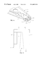
- FIG. 2 is an end view of a slider with a magnetic head of the disk drive as seen in plane 2 — 2 ;
- FIG. 3 is an elevation view of the magnetic disk drive wherein multiple disks and magnetic heads are employed
- FIG. 4 is an isometric illustration of an exemplary suspension system for supporting the slider and magnetic head
- FIG. 5 is an ABS view of the magnetic head taken along plane 5 — 5 of FIG. 2;
- FIG. 6 is a partial view of the slider and a piggyback magnetic head as seen in plane 6 — 6 of FIG. 2;
- FIG. 7 is a partial view of the slider and a merged magnetic head as seen in plane 7 — 7 of FIG. 2;
- FIG. 8 is a partial ABS view of the slider taken along plane 8 — 8 of FIG. 6 to show the read and write elements of the piggyback magnetic head;
- FIG. 9 is a partial ABS view of the slider taken along plane 9 — 9 of FIG. 7 to show the read and write elements of the merged magnetic head;
- FIG. 10 is a view taken along plane 10 — 10 of FIGS. 6 or 7 with all material above the coil layer and leads removed;
- FIG. 11 is an isometric ABS illustration of a read head which employs an AP pinned spin valve (SV) sensor;
- SV AP pinned spin valve
- FIG. 12 is an ABS illustration of a spin valve sensor wherein a nanolayer increases the net uniaxial anisotropy (H K ) of a free layer structure;
- FIG. 13 is a schematic exploded isometric illustration of the free layer structure of FIG. 12;
- FIG. 14 is a schematic exploded isometric illustration of a multilayered free layer structure for explaining a derivation employed in the present invention.
- FIG. 15 is an ABS illustration of a spin valve sensor of the present invention wherein a free layer structure has a low net uniaxial anisotropy (H K ) even though layers employed therein have a high uniaxial anisotropy (H K );
- FIG. 16 is a schematic exploded isometric illustration of the free layer structure of FIG. 15;
- FIG. 17 is a schematic exploded isometric illustration of the free layer structure which is the same as FIG. 16 except the easy axes of the layers are all in the same direction;
- FIG. 18 is a schematic exploded isometric illustration of another embodiment of a free layer structure of the present invention.
- FIG. 19 is a schematic exploded isometric illustration of a further embodiment of a free layer structure of the present invention.
- FIG. 20 is a schematic exploded isometric illustration of still a further free layer structure of the present invention.
- FIG. 21 is an ABS illustration of an antiparallel (AP) pinned layer
- FIG. 22 is an ABS illustration of a single layer pinned layer
- FIG. 23 is an ABS illustration of a tunnel junction sensor employing the present invention.
- FIGS. 24A-24D are steps involved in formation of the multilayered free layer structure shown in FIGS. 15 and 23.
- FIGS. 1-3 illustrate a magnetic disk drive 30 .
- the drive 30 includes a spindle 32 that supports and rotates a magnetic disk 34 .
- the spindle 32 is rotated by a motor 36 that is controlled by a motor controller 38 .
- a combined read and write magnetic head 40 is mounted on a slider 42 that is supported by a suspension 44 and actuator arm 46 .
- a plurality of disks, sliders and suspensions may be employed in a large capacity direct access storage device (DASD) as shown in FIG. 3 .
- the suspension 44 and actuator arm 46 position the slider 42 so that the magnetic head 40 is in a transducing relationship with a surface of the magnetic disk 34 .
- DASD direct access storage device
- the slider When the disk 34 is rotated by the motor 36 the slider is supported on a thin (typically, 0.05 ⁇ m) cushion of air (air bearing) between the surface of the disk 34 and the air bearing surface (ABS) 48 .
- the magnetic head 40 may then be employed for writing information to multiple circular tracks on the surface of the disk 34 , as well as for reading information therefrom.
- Processing circuitry 50 exchanges signals, representing such information, with the head 40 , provides motor drive signals for rotating the magnetic disk 34 , and provides control signals for moving the slider to various tracks.
- the slider 42 In FIG. 4 the slider 42 is shown mounted to a suspension 44 .
- the components described hereinabove may be mounted on a frame 54 of a housing, as shown in FIG. 3 .
- FIG. 5 is an ABS view of the slider 42 and the magnetic head 40 .
- the slider has a center rail 56 that supports the magnetic head 40 , and side rails 58 and 60 .
- the rails 56 , 58 and 60 extend from a cross rail 62 .
- the cross rail 62 is at a leading edge 64 of the slider and the magnetic head 40 is at a trailing edge 66 of the slider.
- FIG. 6 is a side cross-sectional elevation view of a piggyback magnetic head 40 , which includes a write head portion 70 and a read head portion 72 , the read head portion employing an AP pinned spin valve sensor 74 of the present invention.
- FIG. 8 is an ABS view of FIG. 6 .
- the spin valve sensor 74 is sandwiched between nonmagnetic electrically insulative first and second read gap layers 76 and 78 , and the read gap layers are sandwiched between ferromagnetic first and second shield layers 80 and 82 .
- the resistance of the spin valve sensor 74 changes.
- a sense current I S conducted through the sensor causes these resistance changes to be manifested as potential changes. These potential changes are then processed as readback signals by the processing circuitry 50 shown in FIG. 3 .
- the write head portion 70 of the magnetic head 40 includes a coil layer 84 sandwiched between first and second insulation layers 86 and 88 .
- a third insulation layer 90 may be employed for planarizing the head to eliminate ripples in the second insulation layer caused by the coil layer 84 .
- the first, second and third insulation layers are referred to in the art as an “insulation stack”.
- the coil layer 84 and the first, second and third insulation layers 86 , 88 and 90 are sandwiched between first and second pole piece layers 92 and 94 .
- the first and second pole piece layers 92 and 94 are magnetically coupled at a back gap 96 and have first and second pole tips 98 and 100 which are separated by a write gap layer 102 at the ABS.
- first and second solder connections 104 and 106 connect leads from the spin valve sensor 74 to leads 112 and 114 on the suspension 44
- third and fourth solder connections 116 and 118 connect leads 120 and 122 from the coil 84 (see FIG. 8) to leads 124 and 126 on the suspension.
- FIGS. 7 and 9 are the same as FIGS. 6 and 8 except the second shield layer 82 and the first pole piece layer 92 are a common layer.
- This type of head is known as a merged magnetic head.
- the insulation layer 103 of the piggyback head in FIGS. 6 and 8 is omitted.
- FIG. 11 is an isometric ABS illustration of the read head 72 shown in FIG. 6 or 8 .
- the read head 72 includes a spin valve sensor 130 which is located on an antiferromagnetic. (AFM) pinning layer 132 .
- the spin valve sensor 130 has an AP pinned structure, to be described hereinafter, that has its magnetic moments pinned by the magnetic spins of the pinning layer 132 .
- the AFM pinning layer is preferably 425 ⁇ of nickel oxide (NiO).
- First and second hard bias and lead layers 134 and 136 are connected to first and second side edges 138 and 140 of the spin valve sensor. This connection is known in the art as a contiguous junction and is fully described in commonly assigned U.S. Pat. No.
- the first hard bias and lead layers 134 include a first hard bias layer 140 and a first lead layer 142 and the second hard bias and lead layers 136 include a second hard bias layer 144 and a second lead layer 146 .
- the hard bias layers 140 and 144 cause magnetic fields to extend longitudinally through the spin valve sensor 130 for stabilizing the magnetic domains therein.
- the AFM pinning layer 132 , the spin valve sensor 130 and the first and second hard bias and lead layers 134 and 136 are located between nonmagnetic electrically insulative first and second read gap layers 148 and 150 .
- the first and second read gap layers 148 and 150 are, in turn, located between ferromagnetic first and second shield layers 152 and 154 .
- FIG. 12 shows an exemplary spin valve sensor 200 which employs a nanolayer for increasing the magnetoresistive coefficient (dr/R) of the read head.
- the spin valve sensor 200 includes a nonmagnetic electrically conductive spacer layer 202 which is located between a pinned layer structure 204 and a free layer structure 206 .
- the pinned layer structure 204 may be an antiparallel (AP) pinned layer which includes an antiparallel (AP) coupling layer 208 which is located between a first antiparallel (AP 1 ) layer 210 and a second antiparallel (AP 2 ) layer 212 .
- the first AP pinned layer 210 may be exchange coupled to an antiferromagnetic layer 214 via an interlayer 216 .
- the first and second AP pinned layers 210 and 212 are preferably cobalt iron (CoFe). It has been found that an interlayer 216 of nickel iron (NiFe) improves the texture of the cobalt iron (CoFe) material of the first AP pinned layer 210 when it is constructed on a nickel oxide (NiO) AFM layer 214 .
- the free layer structure 206 is a bilayer structure comprising a nanolayer 222 between the spacer layer 202 and a nickel iron (NiFe) free layer 224 .
- a nanolayer of cobalt (Co), or preferably cobalt iron (CoFe), between the spacer layer 202 and the nickel iron (NiFe) free layer 224 increases the magnetoresistive coefficient (dr/R) of the spin valve sensor.
- a drawback to the nanolayer 222 is that cobalt (Co) or cobalt iron (CoFe) has a high uniaxial anisotropy (H K ) which increases the net uniaxial anisotropy (H K ) of the free layer structure 206 .
- the magnetic moment of the free layer structure is parallel to the ABS, as shown at 228 and 230 in FIG. 12, in a quiescent state, namely when the spin valve sensor is not being subjected to flux signals from the rotating magnetic disk.
- the magnetic moments of the layers 222 and 224 are in the same direction since they are exchange coupled together by interfacial engagement.
- the easy axes (ea) are likewise shown parallel to the ABS. Because of its high uniaxial anisotropy the nanolayer 222 is kept at a minimal thickness, such as 10 ⁇ .
- a cap layer 232 of tantalum (Ta) may be formed on the free layer structure 206 .
- FIG. 13 is a schematic exploded isometric illustration of the free layer structure 206 of FIG. 12 with an applied field (H) being applied from a rotating magnetic disk.
- the uniaxial anisotropies (H K ) of each of the layers 222 and 224 combine to increase the overall net uniaxial anisotropy of the free layer structure 206 . This reduces the sensitivity of the sensor.
- anisotropy energy E K is a function of cos 2 ⁇ when the easy axis of the layer is perpendicular to the ABS and is a function of sin 2 ⁇ when the easy axis of the layer is parallel to the ABS.
- Anistropy energy E K can be expressed as
- the exemplary structure includes a first layer 302 of Co 90 Fe 10 , with an easy axis (ea) parallel to the ABS, a uniaxial anisotropy constant k 1 , a thickness t 1 and a magnetic moment M 1 at an angle ⁇ to the ABS, a second layer 304 of Ni 80 Fe 20 with an easy axis (ea) parallel to the ABS, a uniaxial anisotropy constant k 2 , a thickness t 2 and a magnetic moment M 2 at an angle ⁇ to the ABS and a third layer 306 of Co 90 Fe 10 with an easy axis (ea) perpendicular to the ABS, a uniaxial anisotropy constant k 3 , a thickness t 3 and a magnetic moment M 3 at an angle ⁇ to the ABS.
- E is energy of the layers
- bracketed represent anisotropy energy E K energy per area
- H K 2 ⁇ ( k 1 ⁇ t 1 + k 2 ⁇ t 2 - k 3 ⁇ t 3 ) M 1 ⁇ t 1 + M 2 ⁇ t 2 + M 3 ⁇ t 3
- the above relationship can be modified for any number of layers greater than one and the materials can be any ferromagnetic material in any combination.
- FIG. 15 is an ABS illustration of an exemplary embodiment of the present invention.
- the sensor 400 in FIG. 15 is the same as the sensor 200 in FIG. 12 except for the free layer structure 402 .
- the free layer structure 402 includes a nickel iron (NiFe) free layer 404 between first and second free layers 406 and 408 .
- the first layer 406 is a nanolayer which is 10 ⁇ of cobalt iron (CoFe) and the second layer is also 10 ⁇ of cobalt iron (CoFe).
- the magnetic moments (M) of the layers 404 , 406 and 408 are parallel to the ABS. The orientation is the same because all the layers are exchange coupled with respect to one another.
- the easy axis 410 of the first free layer 406 is parallel to the ABS
- the easy axis 412 of the nickel iron (NiFe) free layer 404 is parallel to the ABS
- the easy axis 414 of the second free layer 408 is perpendicular to the ABS.
- An isometric schematic exploded illustration of the free layer structure 402 of FIG. 15 is shown in FIG. 16 .
- the net uniaxial anisotropy (H K ) of the free layer structure 402 shown in FIGS. 15 and 16 is 1.28 Oe.
- FIG. 1 the net uniaxial anisotropy
- the net uniaxial anisotropy (H K ) of this free layer structure is 17.5 Oe. It can be seen that the net uniaxial anisotropy of the free layer structure shown in FIG. 17 is significantly higher than the net uniaxial anisotropy (H K ) of the free layer structure shown in FIG. 16 . In essence, the uniaxial anisotropies (H K ) of the free layers 406 and 408 in FIG. 16 counterbalance one another leaving only the uniaxial anisotropy of the nickel iron (NiFe) free layer 404 as the net uniaxial anisotropy (H K ) of the free layer structure.
- FIG. 18 Another free layer structure embodiment 420 of the present invention is shown in FIG. 18 wherein a first layer 422 is located between second and third layers 424 and 426 , the second and third layers 424 and 426 are located between fourth and fifth layers 428 and 430 and the fourth and fifth layers are located between the sixth and seventh layers 432 and 434 .
- the layers 428 , 422 and 430 may be nickel iron (NiFe) with their easy axes (ea) oriented parallel to the ABS.
- the layers 432 , 424 , 426 and 434 may be cobalt iron (CoFe) with the easy (ea) of the layers 432 and 434 oriented parallel to the ABS and the easy axes of the layers 424 and 426 oriented perpendicular to the ABS. Assuming that the thicknesses of the layers 432 , 424 , 426 and 434 are equal, their uniaxial anisotropies (H K ) will counterbalance one another leaving only the uniaxial anisotropies (H K ) of the nickel iron (NiFe) layers 428 and 422 as the net uniaxial anisotropy (H K ). If each of the layers were made 10 ⁇ thick the overall thickness of the free layer structure would be 70 ⁇ .
- CoFe cobalt iron
- FIG. 19 Another free layer structure 440 , according to the present invention, is shown in FIG. 19 .
- This free layer structure simply employs first and second layers of nickel iron (NiFe) wherein the easy axis (ea) of the first layer 442 is oriented parallel to the ABS and the easy axis (ea) of the second layer 442 is oriented perpendicular to the ABS. If the thickness of the layer 442 is greater than the thickness of the layer 444 the net uniaxial anisotropy will be parallel to the ABS.
- NiFe nickel iron
- the net uniaxial anisotropy (H K ) of the free layer structure 440 is zero and the orientation of the magnetic moment layer will be controlled by an extraneous magnetic force such as the hard bias layers 140 and 144 in FIG. 11 .
- FIG. 20 which employs first and second layers 452 and 454 .
- Each of the layers is cobalt iron (CoFe) with the easy (ea) of the first layer 452 oriented perpendicular to the ABS and the easy axis (ea) of the second layer 454 oriented parallel to the ABS. If the thicknesses of the layers 452 and 454 are equal, once again the net uniaxial anisotropy (H K ) would be equal to zero.
- the second layer 454 is made slightly thicker than the layer 452 so that the magnetic moment of the free layer structure 450 would be oriented parallel to the ABS in a quiescent state.
- FIG. 21 is the antiparallel (AP) structure 204 of FIG. 15 .
- FIG. 22 is a single ferromagnetic pinned layer (P) 460 which can be substituted for the AP pinned layer 204 shown in FIG. 21 .
- the spin valve sensor is referred to as a simple spin valve.
- the spin valve sensor 400 in FIG. 15 is known in the art as a bottom spin valve since the AFM layer is located at the bottom of the sensor and is constructed before the other layers.
- a top spin valve the layers are essentially the same as that shown in FIG. 15 except inverted with the AFM layer being located at the top. It should be understood that the present invention also applies to top spin valves as well as bottom spin valves.
- the tunnel junction sensor includes a spacer layer (S) 502 which is located between a pinned layer (P) 504 and a free layer structure 506 .
- the pinned layer 504 has its magnetic moment 508 pinned perpendicular to the ABS, such as into the paper, by an antiferromagnetic(AFM) pinning layer 510 .
- the pinning layer 510 and the free layer structure 506 may be located between a seed layer 512 and a capping layer 514 and the layers 512 and 514 may be located between first and second shield layers (S 1 ) and (S 2 ) 516 and 518 .
- the tunnel junction sensor 500 differs from the spin valve sensor 400 , shown in FIG. 15, in that the sense current I S in the tunnel junction 500 is directed perpendicular to the planes of the layers of the sensor whereas the sense current I S of the spin valve sensor 400 in FIG. 15 is directed parallel to the planes of the layers of the sensor.
- the free layer structure 506 of the tunnel junction sensor in FIG. 23 may be the same as the free layer structure 402 shown for the spin valve sensor in FIG. 15 .
- a nickel iron (NiFe) layer 520 may be located between first and second layers 522 and 524 wherein the first layer 522 is a nanolayer of 10 ⁇ of cobalt iron (CoFe) and the second layer 524 is also 10 ⁇ of cobalt iron (CoFe).
- the easy axes (ea) 526 and 528 of the layers 522 and 520 are oriented parallel to the ABS and the easy axis (ea) 530 of the layer 534 is oriented perpendicular to the ABS.
- FIGS. 24A-24D illustrate various steps in the construction of the free layer structure shown in FIG. 15 or 23 .
- copper (Cu) is sputter deposited on a wafer substrate to form the spacer layer (S) 202 .
- cobalt iron (CoFe) is sputter deposited in the presence of a field 600 which is directed parallel to the ABS to form the nanolayer 406 with an easy axis (ea) 602 which is oriented parallel to the ABS.
- ea easy axis
- nickel iron (NiFe) is sputter deposited in the presence of a field 604 which is directed parallel to the ABS to form the nickel iron (NiFe) layer 404 with an easy axis (ea) 606 that is oriented parallel to the ABS.
- cobalt iron (CoFe) is sputter deposited in the presence of a field 608 which is oriented perpendicular to the ABS, such as away from the paper, to form the layer 408 with an easy axis (ea) 610 which is oriented parallel to the ABS.
Priority Applications (1)
| Application Number | Priority Date | Filing Date | Title |
|---|---|---|---|
| US09/281,238 US6400536B1 (en) | 1999-03-30 | 1999-03-30 | Low uniaxial anisotropy cobalt iron (COFE) free layer structure for GMR and tunnel junction heads |
Applications Claiming Priority (1)
| Application Number | Priority Date | Filing Date | Title |
|---|---|---|---|
| US09/281,238 US6400536B1 (en) | 1999-03-30 | 1999-03-30 | Low uniaxial anisotropy cobalt iron (COFE) free layer structure for GMR and tunnel junction heads |
Publications (1)
| Publication Number | Publication Date |
|---|---|
| US6400536B1 true US6400536B1 (en) | 2002-06-04 |
Family
ID=23076500
Family Applications (1)
| Application Number | Title | Priority Date | Filing Date |
|---|---|---|---|
| US09/281,238 Expired - Fee Related US6400536B1 (en) | 1999-03-30 | 1999-03-30 | Low uniaxial anisotropy cobalt iron (COFE) free layer structure for GMR and tunnel junction heads |
Country Status (1)
| Country | Link |
|---|---|
| US (1) | US6400536B1 (US06400536-20020604-M00001.png) |
Cited By (22)
| Publication number | Priority date | Publication date | Assignee | Title |
|---|---|---|---|---|
| US20020135923A1 (en) * | 2001-03-20 | 2002-09-26 | International Business Machines Corporation | Tunnel valve sensor having a pinned layer structure with an iron oxide (Fe3O4) layer |
| US20020163765A1 (en) * | 2001-04-09 | 2002-11-07 | International Business Machines Corporation | Spin valve sensor with a biasing layer |
| US6583969B1 (en) * | 2000-04-12 | 2003-06-24 | International Business Machines Corporation | Pinned layer structure having nickel iron film for reducing coercivity of a free layer structure in a spin valve sensor |
| US20030193762A1 (en) * | 2000-08-03 | 2003-10-16 | Kazuhiko Hayashi | Magneto-resistance effect element, magneto-resistance effect head, magneto-resistance transducer system, and magnetic storage system |
| US6655006B2 (en) * | 2001-06-28 | 2003-12-02 | International Business Machines Corporation | Method of making a tunnel junction sensor with a smooth interface between a pinned or free layer and a barrier layer |
| US6662432B2 (en) * | 2001-01-02 | 2003-12-16 | International Business Machines Corporation | Method of making a free layer for a spin valve sensor with a lower uniaxial anisotropy field |
| US20040022108A1 (en) * | 1999-12-20 | 2004-02-05 | Masamichi Saito | Spin valve element and thin film magnetic head |
| US20040023065A1 (en) * | 2002-03-28 | 2004-02-05 | Nve Corporation | Superparamagnetic devices |
| US20040252418A1 (en) * | 2003-06-12 | 2004-12-16 | Headway Technologies, Inc. | Bottom spin valve with laminated CoFe free layer for ultra-high density recording |
| US20050017314A1 (en) * | 2003-07-25 | 2005-01-27 | Hitachi Global Storage Technologies, Inc. | Spin valve transistor with self-pinned antiparallel pinned layer structure |
| US20050024797A1 (en) * | 2001-05-31 | 2005-02-03 | Hitachi Global Storage Technologies Netherlands B.V. | Spin valve sensor with a nitrogen sputtered free layer |
| US20050035383A1 (en) * | 2003-08-12 | 2005-02-17 | Ha Young-Ki | Magnetic tunnel junction and memory device including the same |
| US20050180062A1 (en) * | 2004-02-18 | 2005-08-18 | Ho Kuok S. | GMR sensor with oriented hard bias stabilization |
| US20060196040A1 (en) * | 2005-03-03 | 2006-09-07 | Marie-Claire Cyrille | Method for making a magnetoresistive read head having a pinned layer width greater than the free layer stripe height |
| US20060238925A1 (en) * | 2005-04-22 | 2006-10-26 | Taiwan Semiconductor Manufacturing Company, Ltd. | Magnetoresistive Structures and Fabrication Methods |
| US20060291108A1 (en) * | 2005-06-22 | 2006-12-28 | Tdk Corporation | Exchange-coupled free layer with out-of-plane magnetization |
| US20070171580A1 (en) * | 2006-01-20 | 2007-07-26 | Alps Electric Co., Ltd. | Tunnel type magnetic detection element in which fe composition of top/bottom surface of insulating barrier layer is adjusted and manufacturing method thereof |
| US20080003245A1 (en) * | 2006-06-30 | 2008-01-03 | Beiersdorf Ag | Use of octyl salicylate in cosmetic preparations containing 1,3-dihydroxyacetone |
| US20080100969A1 (en) * | 2006-10-30 | 2008-05-01 | Tomohito Mizuno | Magneto-resistance effect element including free layer having multilayer constitution including magnetic body mixed with element having 4f electrons |
| US20080260943A1 (en) * | 2004-11-30 | 2008-10-23 | Hui-Chuan Wang | Process for composite free layer in CPP GMR or TMR device |
| US20110013317A1 (en) * | 2009-07-16 | 2011-01-20 | Western Digital (Fremont), Llc | Method and system for fabricating magnetic transducers with improved pinning |
| US8227023B1 (en) | 2009-05-27 | 2012-07-24 | Western Digital (Fremont), Llc | Method and system for fabricating magnetic transducers with improved pinning |
Citations (14)
| Publication number | Priority date | Publication date | Assignee | Title |
|---|---|---|---|---|
| US5408377A (en) * | 1993-10-15 | 1995-04-18 | International Business Machines Corporation | Magnetoresistive sensor with improved ferromagnetic sensing layer and magnetic recording system using the sensor |
| US5650958A (en) * | 1996-03-18 | 1997-07-22 | International Business Machines Corporation | Magnetic tunnel junctions with controlled magnetic response |
| US5742162A (en) * | 1996-07-17 | 1998-04-21 | Read-Rite Corporation | Magnetoresistive spin valve sensor with multilayered keeper |
| US5852531A (en) * | 1996-09-20 | 1998-12-22 | Fujitsu Limited | Spinvalve magnetoresistive head and method of manufacturing the same and magnetic recording/reproducing apparatus |
| US5896252A (en) * | 1995-08-11 | 1999-04-20 | Fujitsu Limited | Multilayer spin valve magneto-resistive effect magnetic head with free magnetic layer including two sublayers and magnetic disk drive including same |
| US5991125A (en) * | 1994-09-16 | 1999-11-23 | Kabushiki Kaisha Toshiba | Magnetic head |
| US6038107A (en) * | 1997-10-27 | 2000-03-14 | International Business Machines Corporation | Antiparallel-pinned spin valve sensor |
| US6088195A (en) * | 1996-03-28 | 2000-07-11 | Kabushiki Kaisha Toshiba | Magnetoresistance effect element |
| US6108177A (en) * | 1998-11-19 | 2000-08-22 | International Business Machines Corporation | Tunnel junction structure with FeX ferromagnetic layers |
| US6133732A (en) * | 1996-11-21 | 2000-10-17 | Nec Corporation | Magnetoresistive effect element and shield magnetoresistive effect sensor |
| US6154349A (en) * | 1996-04-26 | 2000-11-28 | Fujitsu Limited | Magnetoresistive transducer including CoFeZ soft magnetic layer |
| US6166948A (en) * | 1999-09-03 | 2000-12-26 | International Business Machines Corporation | Magnetic memory array with magnetic tunnel junction memory cells having flux-closed free layers |
| US6191926B1 (en) * | 1998-05-07 | 2001-02-20 | Seagate Technology Llc | Spin valve magnetoresistive sensor using permanent magnet biased artificial antiferromagnet layer |
| US6201673B1 (en) * | 1999-04-02 | 2001-03-13 | Read-Rite Corporation | System for biasing a synthetic free layer in a magnetoresistance sensor |
-
1999
- 1999-03-30 US US09/281,238 patent/US6400536B1/en not_active Expired - Fee Related
Patent Citations (14)
| Publication number | Priority date | Publication date | Assignee | Title |
|---|---|---|---|---|
| US5408377A (en) * | 1993-10-15 | 1995-04-18 | International Business Machines Corporation | Magnetoresistive sensor with improved ferromagnetic sensing layer and magnetic recording system using the sensor |
| US5991125A (en) * | 1994-09-16 | 1999-11-23 | Kabushiki Kaisha Toshiba | Magnetic head |
| US5896252A (en) * | 1995-08-11 | 1999-04-20 | Fujitsu Limited | Multilayer spin valve magneto-resistive effect magnetic head with free magnetic layer including two sublayers and magnetic disk drive including same |
| US5650958A (en) * | 1996-03-18 | 1997-07-22 | International Business Machines Corporation | Magnetic tunnel junctions with controlled magnetic response |
| US6088195A (en) * | 1996-03-28 | 2000-07-11 | Kabushiki Kaisha Toshiba | Magnetoresistance effect element |
| US6154349A (en) * | 1996-04-26 | 2000-11-28 | Fujitsu Limited | Magnetoresistive transducer including CoFeZ soft magnetic layer |
| US5742162A (en) * | 1996-07-17 | 1998-04-21 | Read-Rite Corporation | Magnetoresistive spin valve sensor with multilayered keeper |
| US5852531A (en) * | 1996-09-20 | 1998-12-22 | Fujitsu Limited | Spinvalve magnetoresistive head and method of manufacturing the same and magnetic recording/reproducing apparatus |
| US6133732A (en) * | 1996-11-21 | 2000-10-17 | Nec Corporation | Magnetoresistive effect element and shield magnetoresistive effect sensor |
| US6038107A (en) * | 1997-10-27 | 2000-03-14 | International Business Machines Corporation | Antiparallel-pinned spin valve sensor |
| US6191926B1 (en) * | 1998-05-07 | 2001-02-20 | Seagate Technology Llc | Spin valve magnetoresistive sensor using permanent magnet biased artificial antiferromagnet layer |
| US6108177A (en) * | 1998-11-19 | 2000-08-22 | International Business Machines Corporation | Tunnel junction structure with FeX ferromagnetic layers |
| US6201673B1 (en) * | 1999-04-02 | 2001-03-13 | Read-Rite Corporation | System for biasing a synthetic free layer in a magnetoresistance sensor |
| US6166948A (en) * | 1999-09-03 | 2000-12-26 | International Business Machines Corporation | Magnetic memory array with magnetic tunnel junction memory cells having flux-closed free layers |
Cited By (60)
| Publication number | Priority date | Publication date | Assignee | Title |
|---|---|---|---|---|
| US6992867B2 (en) | 1999-12-20 | 2006-01-31 | Alps Electric Co., Ltd. | Spin valve element and thin film magnetic head having antiferromagnetic coupled layers |
| US20040023075A1 (en) * | 1999-12-20 | 2004-02-05 | Masamichi Saito | Spin valve element and thin film magnetic head |
| US20040022108A1 (en) * | 1999-12-20 | 2004-02-05 | Masamichi Saito | Spin valve element and thin film magnetic head |
| US7054116B2 (en) | 1999-12-20 | 2006-05-30 | Alps Electric Co., Ltd. | Spin valve element and thin film magnetic head |
| US6583969B1 (en) * | 2000-04-12 | 2003-06-24 | International Business Machines Corporation | Pinned layer structure having nickel iron film for reducing coercivity of a free layer structure in a spin valve sensor |
| US20060232894A1 (en) * | 2000-08-03 | 2006-10-19 | Kazuhiko Hayashi | Magneto-resistance effect element, magneto-resistance effect head, magneto-resistance transducer system, and magnetic storage system |
| US20040174641A1 (en) * | 2000-08-03 | 2004-09-09 | Kazuhiko Hayashi | Magneto-resistance effect element, magneto-resistance effect head, magneto-resistance transducer system, and magnetic storage system |
| US20060268466A1 (en) * | 2000-08-03 | 2006-11-30 | Kazuhiko Hayashi | Magneto-resistance effect element, magneto-resistance effect head, magneto-resistance transducer system, and magnetic storage system |
| US20030193762A1 (en) * | 2000-08-03 | 2003-10-16 | Kazuhiko Hayashi | Magneto-resistance effect element, magneto-resistance effect head, magneto-resistance transducer system, and magnetic storage system |
| US7277261B2 (en) | 2000-08-03 | 2007-10-02 | Nec Corporation | Magneto-resistance effect element, magneto-resistance effect head, magneto-resistance transducer system, and magnetic storage system |
| US7265949B2 (en) | 2000-08-03 | 2007-09-04 | Nec Corporation | Magneto-resistance effect element, magneto-resistance effect head, magneto-resistance transducer system, and magnetic storage system |
| US6747853B2 (en) * | 2000-08-03 | 2004-06-08 | Nec Corporation | Magneto-resistance effect element, magneto-resistance effect head, magneto-resistance transducer system, and magnetic storage system |
| US20060007606A1 (en) * | 2000-08-03 | 2006-01-12 | Kazuhiko Hayashi | Magneto-resistance effect element, magneto-resistance effect head, magneto-resistance transducer system, and magnetic storage system |
| US7161774B2 (en) | 2000-08-03 | 2007-01-09 | Nec Corporation | Magneto-resistance effect element, magneto-resistance effect head, magneto-resistance transducer system, and magnetic storage system |
| US7369375B2 (en) | 2000-08-03 | 2008-05-06 | Nec Corporation | Magneto-resistance effect element and magneto-resistance effect head |
| US6999287B2 (en) | 2000-08-03 | 2006-02-14 | Nec Corporation | Magneto-resistance effect element, magneto-resistance effect head, magneto-resistance transducer system, and magnetic storage system |
| US7158355B2 (en) | 2000-08-03 | 2007-01-02 | Nec Corporation | Magneto-resistance effect element, magneto-resistance effect head, magneto-resistance transducer system, and magnetic storage system |
| US20060274456A1 (en) * | 2000-08-03 | 2006-12-07 | Kazuhiko Hayashi | Magneto-resistance effect element, magneto-resistance effect head, magneto-resistance transducer system, and magnetic storage system |
| US7298596B2 (en) | 2000-08-03 | 2007-11-20 | Nec Corporation | Magneto-resistance effect element, magneto-resistance effect head, magneto-resistance transducer system, and magnetic storage system |
| US6662432B2 (en) * | 2001-01-02 | 2003-12-16 | International Business Machines Corporation | Method of making a free layer for a spin valve sensor with a lower uniaxial anisotropy field |
| US20020135923A1 (en) * | 2001-03-20 | 2002-09-26 | International Business Machines Corporation | Tunnel valve sensor having a pinned layer structure with an iron oxide (Fe3O4) layer |
| US6661626B2 (en) * | 2001-03-20 | 2003-12-09 | International Business Machines Corporation | Tunnel valve sensor having a pinned layer structure with an iron oxide (Fe3O4) layer |
| US6674616B2 (en) * | 2001-04-09 | 2004-01-06 | Hitachi Global Storage Technologies Netherlands B.V. | Spin valve sensor with a biasing layer ecerting a demagnetizing field on a free layer structure |
| US20020163765A1 (en) * | 2001-04-09 | 2002-11-07 | International Business Machines Corporation | Spin valve sensor with a biasing layer |
| US20050024797A1 (en) * | 2001-05-31 | 2005-02-03 | Hitachi Global Storage Technologies Netherlands B.V. | Spin valve sensor with a nitrogen sputtered free layer |
| US7064938B2 (en) * | 2001-05-31 | 2006-06-20 | Hitachi Global Storage Technologies Netherlands B.V. | Spin valve sensor with a nitrogen sputtered free layer |
| US6891704B2 (en) | 2001-06-28 | 2005-05-10 | International Business Machines Corporation | Tunnel junction sensor with a smooth interface between a pinned or free layer and a barrier layer |
| US6655006B2 (en) * | 2001-06-28 | 2003-12-02 | International Business Machines Corporation | Method of making a tunnel junction sensor with a smooth interface between a pinned or free layer and a barrier layer |
| US20060139028A1 (en) * | 2002-03-28 | 2006-06-29 | Nve Corporation | Superparamagnetic field sensing devices |
| US7054118B2 (en) * | 2002-03-28 | 2006-05-30 | Nve Corporation | Superparamagnetic field sensing devices |
| US7355822B2 (en) * | 2002-03-28 | 2008-04-08 | Nve Corporation | Superparamagnetic field sensing device |
| US7660081B2 (en) * | 2002-03-28 | 2010-02-09 | Nve Corporation | Superparamagnetic platelets field sensing devices |
| US20040023065A1 (en) * | 2002-03-28 | 2004-02-05 | Nve Corporation | Superparamagnetic devices |
| US7536772B2 (en) | 2003-06-12 | 2009-05-26 | Headway Technologies, Inc. | Method of manufacturing a bottom spin valve with a laminated CoFe free layer |
| US20060056116A1 (en) * | 2003-06-12 | 2006-03-16 | Headway Technologies, Inc. | Bottom spin valve with laminated CoFe free layer for ultra-high density recording |
| US6993827B2 (en) | 2003-06-12 | 2006-02-07 | Headway Technologies, Inc. | Method of making a bottom spin valve |
| US7542249B2 (en) | 2003-06-12 | 2009-06-02 | Headway Technologies, Inc. | Bottom spin valve with laminated CoFe free layer for ultra-high density recording |
| US20040252418A1 (en) * | 2003-06-12 | 2004-12-16 | Headway Technologies, Inc. | Bottom spin valve with laminated CoFe free layer for ultra-high density recording |
| US20050017314A1 (en) * | 2003-07-25 | 2005-01-27 | Hitachi Global Storage Technologies, Inc. | Spin valve transistor with self-pinned antiparallel pinned layer structure |
| US7084467B2 (en) * | 2003-07-25 | 2006-08-01 | Hitachi Global Storage Technologies Netherlands B.V. | Spin valve transistor with self-pinned antiparallel pinned layer structure |
| US20050035383A1 (en) * | 2003-08-12 | 2005-02-17 | Ha Young-Ki | Magnetic tunnel junction and memory device including the same |
| US7378698B2 (en) * | 2003-08-12 | 2008-05-27 | Samsung Electronics Co., Ltd. | Magnetic tunnel junction and memory device including the same |
| US7161763B2 (en) * | 2004-02-18 | 2007-01-09 | Hitachi Global Storage Technologies Netherlands B.V. | GMR sensor with oriented hard bias stabilization |
| US20050180062A1 (en) * | 2004-02-18 | 2005-08-18 | Ho Kuok S. | GMR sensor with oriented hard bias stabilization |
| US20080260943A1 (en) * | 2004-11-30 | 2008-10-23 | Hui-Chuan Wang | Process for composite free layer in CPP GMR or TMR device |
| US8105703B2 (en) * | 2004-11-30 | 2012-01-31 | Headway Technologies, Inc. | Process for composite free layer in CPP GMR or TMR device |
| US7346977B2 (en) * | 2005-03-03 | 2008-03-25 | Hitachi Global Storage Technologies Netherlands B.V. | Method for making a magnetoresistive read head having a pinned layer width greater than the free layer stripe height |
| US20060196040A1 (en) * | 2005-03-03 | 2006-09-07 | Marie-Claire Cyrille | Method for making a magnetoresistive read head having a pinned layer width greater than the free layer stripe height |
| US7443638B2 (en) * | 2005-04-22 | 2008-10-28 | Taiwan Semiconductor Manufacturing Company Ltd. | Magnetoresistive structures and fabrication methods |
| US20060238925A1 (en) * | 2005-04-22 | 2006-10-26 | Taiwan Semiconductor Manufacturing Company, Ltd. | Magnetoresistive Structures and Fabrication Methods |
| US7602591B2 (en) * | 2005-06-22 | 2009-10-13 | Tdk Corporation | Exchange-coupled free layer with out-of-plane magnetization |
| US20060291108A1 (en) * | 2005-06-22 | 2006-12-28 | Tdk Corporation | Exchange-coupled free layer with out-of-plane magnetization |
| US20070171580A1 (en) * | 2006-01-20 | 2007-07-26 | Alps Electric Co., Ltd. | Tunnel type magnetic detection element in which fe composition of top/bottom surface of insulating barrier layer is adjusted and manufacturing method thereof |
| US20080003245A1 (en) * | 2006-06-30 | 2008-01-03 | Beiersdorf Ag | Use of octyl salicylate in cosmetic preparations containing 1,3-dihydroxyacetone |
| US20080100969A1 (en) * | 2006-10-30 | 2008-05-01 | Tomohito Mizuno | Magneto-resistance effect element including free layer having multilayer constitution including magnetic body mixed with element having 4f electrons |
| US8203808B2 (en) * | 2006-10-30 | 2012-06-19 | Tdk Corporation | Magneto-resistance effect element including free layer having multilayer constitution including magnetic body mixed with element having 4F electrons |
| US8227023B1 (en) | 2009-05-27 | 2012-07-24 | Western Digital (Fremont), Llc | Method and system for fabricating magnetic transducers with improved pinning |
| US9007728B1 (en) | 2009-05-27 | 2015-04-14 | Western Digital (Fremont), Llc | Method and system for fabricating magnetic transducers with improved pinning |
| US20110013317A1 (en) * | 2009-07-16 | 2011-01-20 | Western Digital (Fremont), Llc | Method and system for fabricating magnetic transducers with improved pinning |
| US8164864B2 (en) * | 2009-07-16 | 2012-04-24 | Western Digital (Fremont), Llc | Method and system for fabricating magnetic transducers with improved pinning |
Similar Documents
| Publication | Publication Date | Title |
|---|---|---|
| US6655008B2 (en) | Method of making a dual GMR read head with self-pinned layer and specular reflector | |
| US6400536B1 (en) | Low uniaxial anisotropy cobalt iron (COFE) free layer structure for GMR and tunnel junction heads | |
| US6353518B2 (en) | Spin valve sensor having antiparallel (AP) pinned layer structure with low coercivity and high resistance | |
| US6295187B1 (en) | Spin valve sensor with stable antiparallel pinned layer structure exchange coupled to a nickel oxide pinning layer | |
| US6185080B1 (en) | Dual tunnel junction sensor with a single antiferromagnetic layer | |
| US6108177A (en) | Tunnel junction structure with FeX ferromagnetic layers | |
| US6580589B1 (en) | Pinned layer structure for a spin valve sensor having cobalt iron (CoFe) and cobalt iron oxide (CoFeO) laminated layers | |
| US5666248A (en) | Magnetizations of pinned and free layers of a spin valve sensor set by sense current fields | |
| US6381106B1 (en) | Top spin valve sensor that has a free layer structure with a cobalt iron boron (cofeb) layer | |
| US6181537B1 (en) | Tunnel junction structure with junction layer embedded in amorphous ferromagnetic layers | |
| US6278589B1 (en) | Dual GMR sensor with a single AFM layer | |
| US20030179516A1 (en) | High magnetoresistance spin valve sensor with self-pinned antiparallel (AP) pinned layer structure | |
| US6282068B1 (en) | Antiparallel (AP) pinned read head with improved GMR | |
| US7177120B2 (en) | Self-pinned spin valve sensor with a high coercivity antiparallel (AP) pinned layer | |
| US6661626B2 (en) | Tunnel valve sensor having a pinned layer structure with an iron oxide (Fe3O4) layer | |
| US6317298B1 (en) | Spin valve read sensor with specular reflector structure between a free layer structure and a keeper layer | |
| US6859348B2 (en) | Hard biased self-pinned spin valve sensor with recessed overlaid leads | |
| US6665155B2 (en) | Spin valve sensor with free layer structure having a cobalt niobium (CoNb) or cobalt niobium hafnium (CoNbHf) layer | |
| US6549383B1 (en) | Pinned layer having a CoFeNb or CoFeNbHf film for increasing magnetic softness and reducing current shunting | |
| US6700755B2 (en) | Spin valve sensor with modified magnetostriction | |
| US6624988B2 (en) | Tunnel junction sensor with antiparallel (AP) coupled flux guide | |
| US6525911B1 (en) | Permeability offset of shield layers for correcting bias of a free layer structure in a spin valve sensor | |
| US6430014B1 (en) | Properly biased AP pinned spin valve sensor with a metallic pinning layer and no read gap offset | |
| US6201672B1 (en) | Spin valve sensor having improved interface between pinning layer and pinned layer structure | |
| US6580588B1 (en) | Resettable dual AP pinned valve sensor insensitive to sense current direction and having symmetrically balanced fields about a free layer |
Legal Events
| Date | Code | Title | Description |
|---|---|---|---|
| AS | Assignment |
Owner name: INTERNATIONAL BUSINESS MACHINES CORPORATION, NEW Y Free format text: ASSIGNMENT OF ASSIGNORS INTEREST;ASSIGNOR:GILL, HARDAYAL SINGH;REEL/FRAME:009876/0080 Effective date: 19990324 |
|
| AS | Assignment |
Owner name: HITACHI GLOBAL STORAGE TECHNOLOGIES NETHERLANDS B. Free format text: CHANGE OF NAME;ASSIGNOR:MARIANA HDD B.V.;REEL/FRAME:014871/0450 Effective date: 20021231 Owner name: MARIANA HDD B.V., NETHERLANDS Free format text: ASSIGNMENT OF ASSIGNORS INTEREST;ASSIGNOR:INTERNATIONAL BUSINESS MACHINES CORPORATION;REEL/FRAME:014871/0746 Effective date: 20021231 |
|
| FPAY | Fee payment |
Year of fee payment: 4 |
|
| REMI | Maintenance fee reminder mailed | ||
| LAPS | Lapse for failure to pay maintenance fees | ||
| STCH | Information on status: patent discontinuation |
Free format text: PATENT EXPIRED DUE TO NONPAYMENT OF MAINTENANCE FEES UNDER 37 CFR 1.362 |
|
| FP | Lapsed due to failure to pay maintenance fee |
Effective date: 20100604 |